Other Parts Discussed in Thread: TMS320F28035
My intention is to use the DRV8836DSSR chip to drive the hollow cup motor, but now there are some problems that I can't solve.
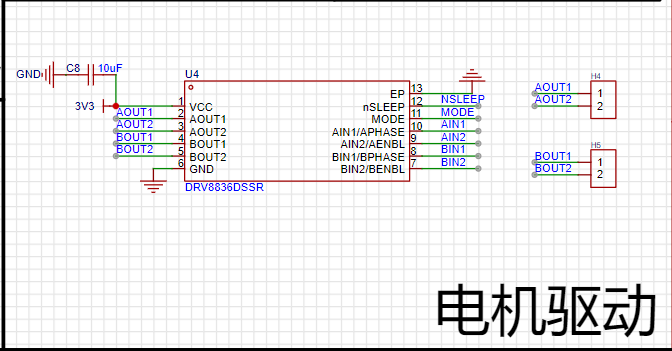
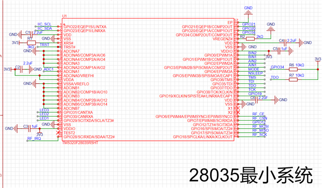
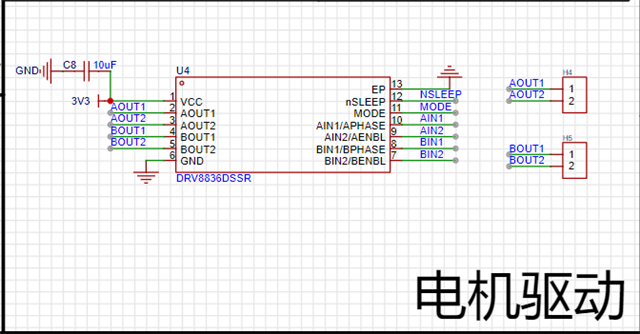
The main control chip I use is TMS320F28035 (56 pin) chip,The hardware schematic diagram of the main control chip and the DRV8836 chip is as follows:
According to the schematic diagram, we can clearly see the connection relationship between the main control chip and DRV8836.
The complete code for CCS to regulate DRV8836 using EPWM1 and EPWM2 is as follows:
The first is the main.c file:
#include "Config.h"
extern Uint16 RamfuncsLoadSize;

void main(void)
{
    InitSysCtrl();
    DINT;
    InitPieCtrl();
    IER = 0x0000;
    IFR = 0x0000;
    InitPieVectTable();
    memcpy(&RamfuncsRunStart, &RamfuncsLoadStart, (Uint32)&RamfuncsLoadSize);
    LED_Init();              // 初始化LED-
    InitMotor();            // 初始化电机-
    Timer0_init();         // 定时器0初始化,1ms周期中断-
    PieCtrlRegs.PIECTRL.bit.ENPIE = 1;
    EINT;
    ERTM;

    while(1)
        {
        int f=900;
    /* 实现的任务1(10ms为一个周期):
    * 调控电机油门或转向*/
            if(timer0Base.loop100HzCnt >= 10)
            {
                timer0Base.loop100HzCnt = 0;
                LED2_TOGGLE;
                DELAY_US(200*1000);
                MotorPwmFlash(f,2);
                LED3_TOGGLE;
            }
        }
}
moto.c file:
#include "stdio.h"
#include "Moto.h"
uint8_t Turningmodeselection=Noturn;
uint16_t MOTO1_PWM=0;
/*******************************************************************************
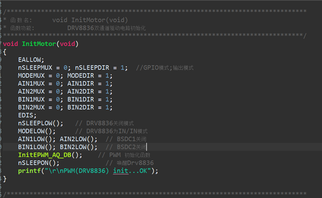
* 函 数 名: void InitMotor(void)
* 函数功能: DRV8836双通道驱动电路初始化
*******************************************************************************/
void InitMotor(void)
{
EALLOW;
nSLEEPMUX = 0; nSLEEPDIR = 1; //GPIO模式;输出模式
MODEMUX = 0; MODEDIR = 1;
AIN1MUX = 0; AIN1DIR = 1;
AIN2MUX = 0; AIN2DIR = 1;
BIN1MUX = 0; BIN1DIR = 1;
BIN2MUX = 0; BIN2DIR = 1;
EDIS;
nSLEEPLOW(); // DRV8836关闭模式
MODELOW(); // DRV8836为IN/IN模式
AIN1LOW(); AIN2LOW(); // BSDC1关闭
BIN1LOW(); BIN2LOW(); // BSDC2关闭
InitEPWM_AQ_DB(); // PWM 初始化函数
nSLEEPON(); // 唤醒Drv8836
printf("\r\nPWM(DRV8836) init...OK");
}
/*******************************************************************************
* 函 数 名: void InitEPWM_AQ_DB(void)
* 函数功能: PWM1/2初始化
*******************************************************************************/
void InitEPWM_AQ_DB(void)
{
char i;
volatile struct EPWM_REGS *PWMDef[] = {&EPwm1Regs,&EPwm1Regs,&EPwm2Regs,&EPwm3Regs,&EPwm4Regs,&EPwm5Regs,&EPwm6Regs};
EALLOW;
SysCtrlRegs.PCLKCR0.bit.TBCLKSYNC =0; //失能时基模块时钟
SysCtrlRegs.PCLKCR1.bit.EPWM1ENCLK =1; //时钟启用
SysCtrlRegs.PCLKCR1.bit.EPWM2ENCLK =1; //时钟启用
EDIS;
InitEPwmGpio(); //开启时钟及初始化配置
EALLOW;
PieVectTable.EPWM1_INT = &epwm1_isr;
PieVectTable.EPWM2_INT = &epwm2_isr;
EDIS;
for(i=1;i<4;i++)
{
EALLOW;
PWMDef[i]->TBCTL.bit.CTRMODE = TB_COUNT_UP; // 递增计数模式
PWMDef[i]->TBPRD = EPWM_TIMER_TBPRD; // 设置定时器周期
PWMDef[i]->TBCTL.bit.PHSEN = TB_DISABLE; // 禁止相位加载
PWMDef[i]->TBPHS.half.TBPHS = 0x0000; // 时基相位寄存器的值赋值0
PWMDef[i]->TBCTR = 0x0000; // 时基计数器清零,时基计数器为16 位, 读该寄存器的值可以得到时基计数器 (TBCTR) 的值。 写该寄存器可以设置时基计数器的值。
PWMDef[i]->TBCTL.bit.HSPCLKDIV = HTB_DIV1; // SYSCLKOUT=60M HZ
PWMDef[i]->TBCTL.bit.CLKDIV = TB_DIV64; // 设置时基时钟速率
PWMDef[i]->CMPCTL.bit.SHDWAMODE = CC_SHADOW; //设置影子
PWMDef[i]->CMPCTL.bit.SHDWBMODE = CC_SHADOW;
PWMDef[i]->CMPCTL.bit.LOADAMODE = CC_CTR_ZERO; //设置加载模式,0加载
PWMDef[i]->CMPCTL.bit.LOADBMODE = CC_CTR_ZERO;
// 设置比较寄存器的值
PWMDef[i]->CMPA.half.CMPA = 0; // 清零
PWMDef[i]->CMPB = 0; // 清零
// 设置动作限定;首先默认为转动方向为正转,这时只有PWMiA输出占空比;
PWMDef[i]->AQCTLA.bit.ZRO = AQ_SET; // 计数到0时PWMxA输出高电平
PWMDef[i]->AQCTLA.bit.CAU = AQ_CLEAR; // 递增计数时,发生比较寄存器A匹配时清除PWMxA输出
PWMDef[i]->AQCTLB.bit.ZRO = AQ_CLEAR; // 计数到0时PWMxB输出低电平
PWMDef[i]->AQCTLB.bit.CBU = AQ_CLEAR; // 递增计数时,发生比较寄存器A匹配时清除PWMxB输出
// 1次0匹配事件发生时产生一个中断请求;
PWMDef[i]->ETSEL.bit.INTSEL = ET_CTR_ZERO; // 选择0匹配事件中断
PWMDef[i]->ETSEL.bit.INTEN = 1; // 使能事件触发中断
PWMDef[i]->ETPS.bit.INTPRD = ET_1ST; // 1次事件产生中断请求
EDIS;
}
EALLOW;
SysCtrlRegs.PCLKCR0.bit.TBCLKSYNC =1;
EDIS;
IER |= M_INT3; //中断初始化
PieCtrlRegs.PIEIER3.bit.INTx1 = 1;
PieCtrlRegs.PIEIER3.bit.INTx2 = 1;
}
/*******************************************************************************
* 函 数 名: interrupt void epwm1_isr(void)
* 函数功能: 控制尾翼电机的转速
*******************************************************************************/
interrupt void epwm1_isr(void)
{
switch (Turningmodeselection){
case Noturn:
//保证下面EPWMA和EPWMB相互切换同时输出0电平;
EPwm1Regs.CMPA.half.CMPA = 0;//改变脉宽
EPwm1Regs.CMPB = 0; //改变脉宽
break;
case Turnleft:
//保证下面EPWMA和EPWMB相互切换同时输出0电平;
EPwm1Regs.CMPA.half.CMPA = 0;//改变脉宽
EPwm1Regs.CMPB = 0; //改变脉宽
EPwm1Regs.AQCTLA.bit.ZRO = AQ_CLEAR; // 计数到0时PWM1A输出低电平
EPwm1Regs.AQCTLA.bit.CAU = AQ_CLEAR; // 递增计数时,发生比较寄存器A匹配时清除PWM1A输出
EPwm1Regs.AQCTLB.bit.ZRO = AQ_SET; // 计数到0时PWM1B输出高电平
EPwm1Regs.AQCTLB.bit.CBU = AQ_CLEAR; // 递增计数时,发生比较寄存器A匹配时清除PWM1B输出
EPwm1Regs.CMPA.half.CMPA = Vertailmotor_PWM;
EPwm1Regs.CMPB = Vertailmotor_PWM;
break;
case Turnright:
//保证下面EPWMA和EPWMB相互切换同时输出0电平;
EPwm1Regs.CMPA.half.CMPA = 0;//改变脉宽
EPwm1Regs.CMPB = 0; //改变脉宽
EPwm1Regs.AQCTLA.bit.ZRO = AQ_SET; // 计数到0时PWM1A输出高电平
EPwm1Regs.AQCTLA.bit.CAU = AQ_CLEAR; // 递增计数时,发生比较寄存器A匹配时清除PWM1A输出
EPwm1Regs.AQCTLB.bit.ZRO = AQ_CLEAR; // 计数到0时PWM1B输出低电平
EPwm1Regs.AQCTLB.bit.CBU = AQ_CLEAR; // 递增计数时,发生比较寄存器A匹配时清除PWM1B输出
EPwm1Regs.CMPA.half.CMPA = Vertailmotor_PWM;
EPwm1Regs.CMPB = Vertailmotor_PWM;
break;
default:
break;} // end switch
EPwm1Regs.ETCLR.bit.INT = 1; // 清除中断标志位
PieCtrlRegs.PIEACK.all = PIEACK_GROUP3; // 清除PIE应答寄存器
}
/*******************************************************************************
* 函 数 名: interrupt void epwm2_isr(void)
* 函数功能: 控制机翼电机的转速
*******************************************************************************/
interrupt void epwm2_isr(void)
{
if(MOTO1_PWM>=CMPX_MAX) MOTO1_PWM = CMPX_MAX;
if(MOTO1_PWM<=CMPX_MIN) MOTO1_PWM = CMPX_MIN;
EPwm2Regs.CMPA.half.CMPA = MOTO1_PWM;
EPwm2Regs.ETCLR.bit.INT = 1; // 清除中断标志位
PieCtrlRegs.PIEACK.all = PIEACK_GROUP3; // 清除PIE应答寄存器
}
/*******************************************************************************
* 函 数 名: void MotorPwmFlash(int16_t MOTO1_PWM,int16_t MOTO2_DELAY,uint8_t Turningmodeselection)
* 函数功能: 更新主翼电机占空比和尾翼转向
*******************************************************************************/
void MotorPwmFlash(int16_t MOTO1_PWM2,uint8_t Turningmodeselecting)
{
MOTO1_PWM=MOTO1_PWM2;
Turningmodeselection=Turningmodeselecting;
}
moto.h
#ifndef INC_MOTO_H_
#define INC_MOTO_H_

#include "extern_variable.h"

#define PWM_FRE 600000
#define EPWM_TIMER_TBPRD  999

/* 电机档位定义*/
#define CMPX_MIN         0
#define CMPX_HALF        500
#define CMPX_MAX         999
#define Vertailmotor_PWM 300
extern uint8_t Turningmodeselection;
extern uint16_t MOTO1_PWM;
enum {Noturn = 0,Turnleft,Turnright};
#define nSLEEP GPIO5
#define nSLEEPMUX GpioCtrlRegs.GPAMUX1.bit.nSLEEP
#define nSLEEPDIR GpioCtrlRegs.GPADIR.bit.nSLEEP
#define nSLEEPTOGGLE()  GpioDataRegs.GPATOGGLE.bit.nSLEEP = 1
#define nSLEEPON()  GpioDataRegs.GPASET.bit.nSLEEP =1
#define nSLEEPLOW() GpioDataRegs.GPACLEAR.bit.nSLEEP =1
#define MODE GPIO4
#define MODEMUX GpioCtrlRegs.GPAMUX1.bit.MODE
#define MODEDIR GpioCtrlRegs.GPADIR.bit.MODE
#define MODETOGGLE()  GpioDataRegs.GPATOGGLE.bit.MODE = 1
#define MODEON()  GpioDataRegs.GPASET.bit.MODE =1
#define MODELOW()  GpioDataRegs.GPACLEAR.bit.MODE =1
#define BIN2 GPIO0
#define BIN2MUX GpioCtrlRegs.GPAMUX1.bit.BIN2
#define BIN2DIR GpioCtrlRegs.GPADIR.bit.BIN2
#define BIN2TOGGLE()  GpioDataRegs.GPATOGGLE.bit.BIN2 = 1
#define BIN2ON()  GpioDataRegs.GPASET.bit.BIN2 =1
#define BIN2LOW()  GpioDataRegs.GPACLEAR.bit.BIN2 =1
#define BIN1 GPIO1
#define BIN1MUX GpioCtrlRegs.GPAMUX1.bit.BIN1
#define BIN1DIR GpioCtrlRegs.GPADIR.bit.BIN1
#define BIN1TOGGLE()  GpioDataRegs.GPATOGGLE.bit.BIN1 = 1
#define BIN1ON()  GpioDataRegs.GPASET.bit.BIN1 =1
#define BIN1LOW()  GpioDataRegs.GPACLEAR.bit.BIN1 =1
#define AIN2 GPIO2
#define AIN2MUX GpioCtrlRegs.GPAMUX1.bit.AIN2
#define AIN2DIR GpioCtrlRegs.GPADIR.bit.AIN2
#define AIN2TOGGLE()  GpioDataRegs.GPATOGGLE.bit.AIN2 = 1
#define AIN2ON()  GpioDataRegs.GPASET.bit.AIN2 =1
#define AIN2LOW()  GpioDataRegs.GPACLEAR.bit.AIN2 =1
#define AIN1 GPIO3
#define AIN1MUX GpioCtrlRegs.GPAMUX1.bit.AIN1
#define AIN1DIR GpioCtrlRegs.GPADIR.bit.AIN1
#define AIN1TOGGLE()  GpioDataRegs.GPATOGGLE.bit.AIN1 = 1
#define AIN1ON()  GpioDataRegs.GPASET.bit.AIN1 =1
#define AIN1LOW()  GpioDataRegs.GPACLEAR.bit.AIN1 =1

/* 包含头文件*/
void InitMotor(void);
void InitEPWM_AQ_DB(void);
void MotorPwm1Flash(int16_t MOTO1_PWM);
interrupt void epwm1_isr(void);
void MotorPwm2Flash(uint8_t Turningmodeselection);
interrupt void epwm2_isr(void);
void MotorPwmFlash(int16_t MOTO1_PWM,uint8_t Turningmodeselection);

#endif /* INC_MOTO_H_ */
This code can run normally, I personally think there is no problem with this code, but the motor can not rotate normally, so I don't know where the problem is.
When the code is running normally, I expect the picture to appear is that the hollow cup motor with a rated voltage of 3.7V can rotate normally,
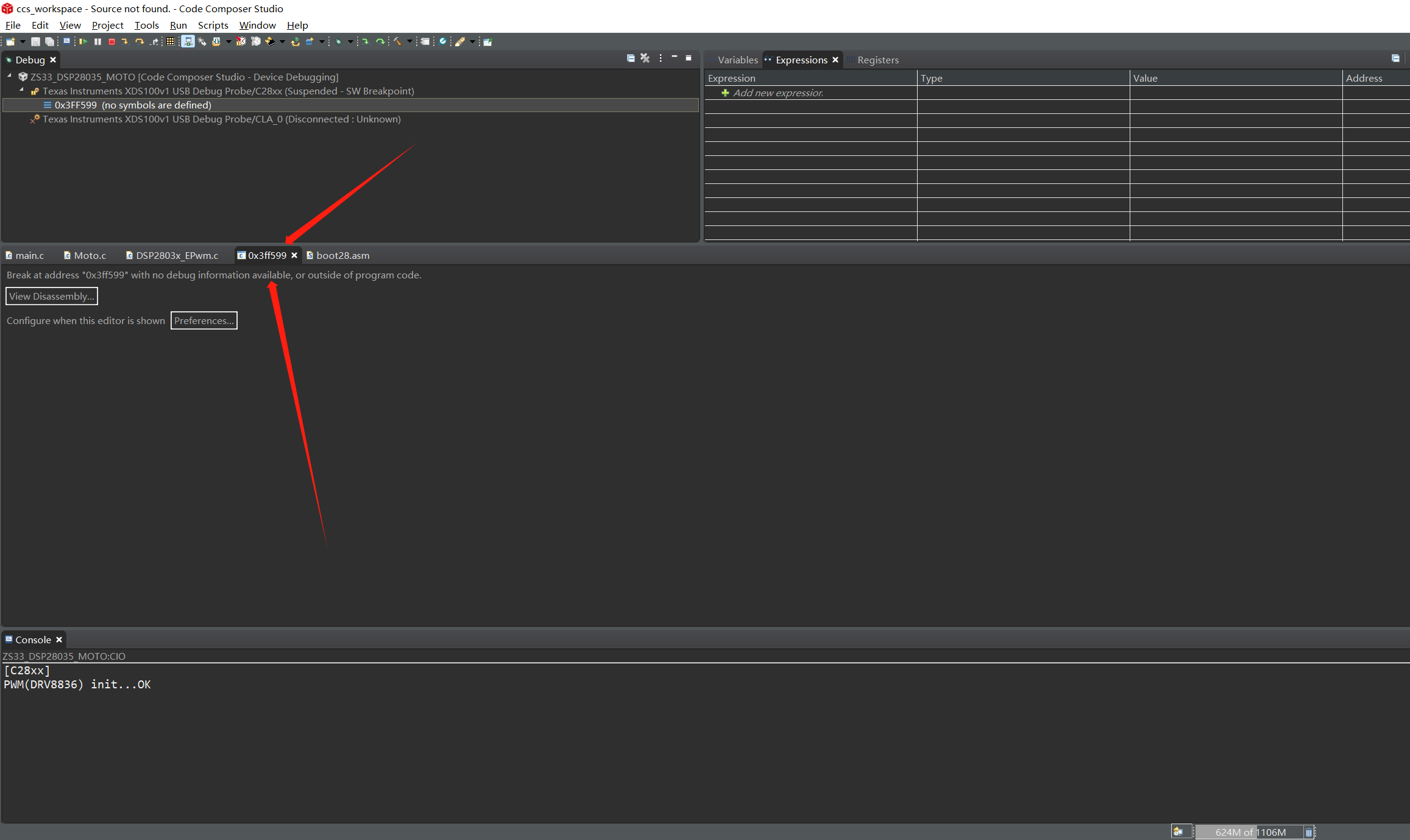
However, the actual situation is that the motor does not rotate at all, and the CCS software interface jumps to a strange interface, as shown in the following figure.
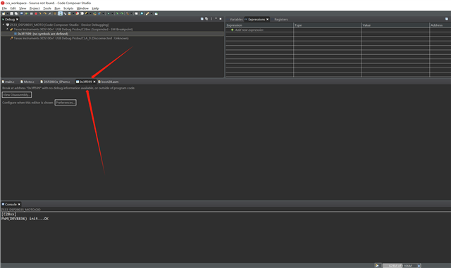
The two wires of the hollow cup motor are correctly connected to the (AOUT1, AOUT2) or (BOUT1, BOUT2) interface, the motor not only does not react, but the software will enter the interface above.
Although the rated voltage of the hollow cup motor is 3.7V, it can be rotated with a voltage of 1.5V connected to the motor.
The power supply voltage I gave DRV8836 was 3.3V for the whole circuit after the 1S lithium battery voltage division, and I did not directly connect the 1S lithium battery to the DRV8836 (VCC and GND).
In my test, I found that under normal operation, when I connect (AOUT1 directly to AOUT2) or (BOUT1 directly to BOUT2), the CCS interface in the above figure will also appear.
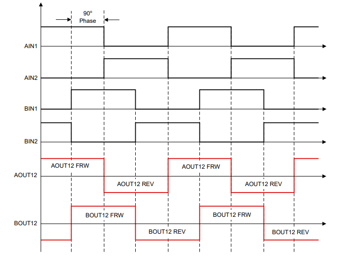
I used EPWM2A to connect AIN2 and EPWM2B to connect AIN1, and the duty cycle given was 80%. I correctly observed the waveform with the oscilloscope. According to the expected calculation, the voltage output of the AOUT1 and AOUT2 pins is 3.3V*0.8=2.64V, which is enough to drive the hollow cup motor, but the motor does not move after insertion and the software stops Debug.
I don't know where the problem is, so I would like to ask the following questions :
1. Is there a problem with my code?
2. There is a problem with the hardware circuit (should the 1S lithium battery be directly connected to VCC and GND of 8836?)
3.Why does CCS have an unfamiliar interface like the one above? (I'm using the XDS100V1 emulator)
4.How can I configure the hollow cup motor to run properly?
I am eager to get your help. Thank you!
Very anxious!!!
Very anxious!!!