Other Parts Discussed in Thread: MCF8316A, ,
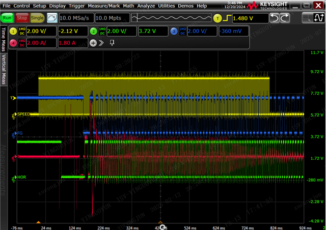
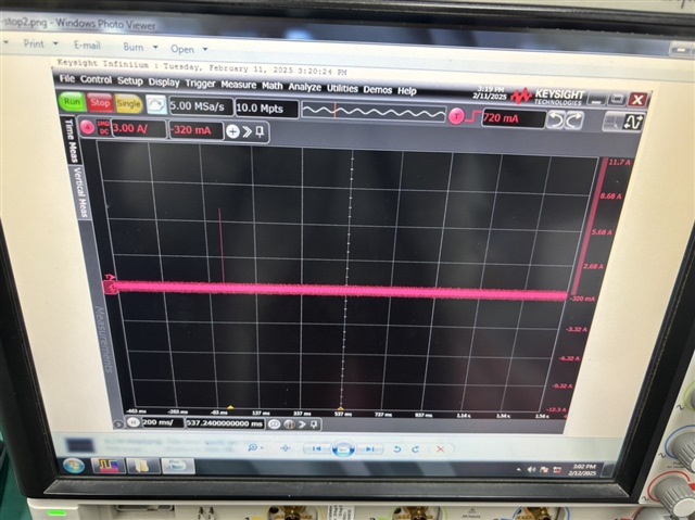
When the positive and negative direction control motor of the driver is frequently used, the driver chip does not work, which can only be solved by power-on and power-off,STM32F4 was used to communicate with the driver chip, during which neither E0 nor E2 address of the motor fault was reported, and the motor round-trip movement time was about 2~3s. After a sustained period of time, the motor did not move and the driver chip did not have pulse output, which could only be solved by power-on and power-off. The power supply was 24v, and no driver chip error was reported during the movement. The following is the EEPROM configuration we used.
0x80:0x7E002080;
0xA4:0x2;
0xA6:0x20000000;
0x8A:0x79FE4111;
0x84:0x31fb109c;
0x82:0x4e261d84;
0x86:0x14461200;
0x88:0x44964C0;
0x8C:0x1da724;
0x8e:0xa00510;
0x90:0x5DC045A6;
0x96:0x6adb44a6;
0x98:0x392dff80;
0x9c:0x3f980000;
0x92:0x60f43025;
0x94:0x14E6E409;
0xac:0x58443430;
0xae:0x50A00000;
0xa8:0x7fff0000;
0x9a:0x548a186;