This thread has been locked.

If you have a related question, please click the "Ask a related question" button in the top right corner. The newly created question will be automatically linked to this question.

BQ76952: DSG引脚,在关断的时候震荡

Part Number: BQ76952

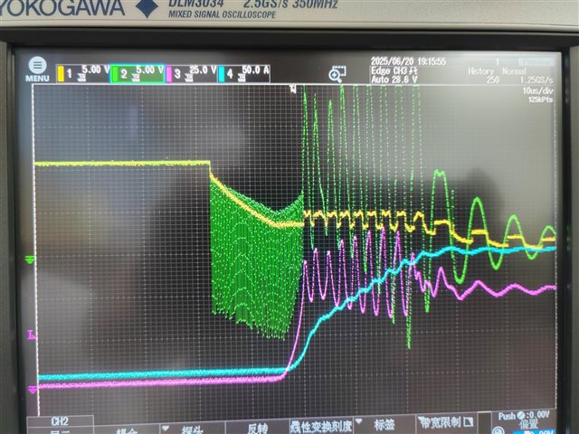
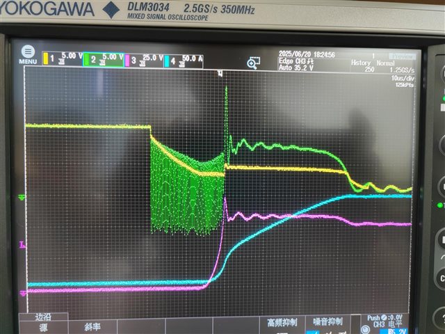
如上两张图片,黄色:放电MOS关Vgs,绿色:DSG引脚,红色:放电MOS管Vds,蓝色:PACK输出电流;

现象:两个版本的测试图片,左图是新版本,DSG引脚震荡,右图是旧版本,无次震荡;

问题:经过查找、对比原理图、PCB文件,没有找出差异,现在不清楚为什么DSG会震荡?需要协助查找原因以及解决办法

已经处理过的:通过对换MOS,已经明确确定是新版本的PCB或者原理图哪里有影响,旧版本的PCB没有问题, 并且PIN46-PIN47脚的电容电压是稳定的,没有发现震荡现象

  • 已经收到了您的案例,调查需要些时间,感谢您的耐心等待。

  • 非常期待您的快速响应,这个问题,让我非常着急

  • 还能再加快一些速度吗?

    我需要一些答案或者指点

    谢谢

  • 您好

    初始振荡看起来可能是我们器件 DSG 引脚的 FET 驱动器关断的一部分。 我们的器件将首先开始向 VSS 对 DSG 引脚放电、但为了防止 DSG FET 栅极被驱动到显著低于 PACK+的水平、我们的器件会监测 LD 引脚电压、并在 DSG 引脚电压降至 LD 引脚电压以下时停止放电。 我们的器件会在一段时间内的一系列脉冲中多次执行此操作、以便将 DSG 栅极放电至 LD 引脚的电压。 数据表中的第16.5节 FET 驱动器关断和第8节来自多个 FET 的 DSG 驱动器应用手册进一步讨论了此行为并显示了此行为的波形。

    如果波形显示的振荡超过~200us、则它与 FET 选择及其周围的电路更相关。 此 MOSFET 常见问题解答中的第4项可能会部分解释您在更换 FET 之前会看到额外振荡的原因。

  • Thank you very much for your reply; however, this did not eliminate my doubts.

    1、We have two versions of the PCB board, V01 and V02. The V01 version is normal, as shown in the upper left picture. However, the Vds of the V02 version will oscillate severely. We swapped the two versions of the MOS FET, but the problem still couldn't be solved.

    2、The high-frequency oscillation at the beginning of the DSG output pin is known to be an inherent phenomenon of this device. The main problem lies in the relatively small frequency fluctuations at the end, which is the culprit. We still haven't been able to pinpoint the cause.

    3、We have checked the influence of the MOS field-effect transistor itself and the circuit connections. We also compared it with the previous PCB layout. So far, we still can't determine the cause. Please help analyze it. Your assistance is still needed for further investigation of the cause.

  • 您好

    已经处理过的:通过对换MOS,已经明确确定是新版本的PCB或者原理图哪里有影响,旧版本的PCB没有问题, 并且PIN46-PIN47脚的电容电压是稳定的,没有发现震荡现象

    I'm a little confused now. The statement above here says that by changing the MOSFET, no oscillations were further observed. 

    The main problem lies in the relatively small frequency fluctuations at the end, which is the culprit. We still haven't been able to pinpoint the cause.

    Do you mind sharing your schematic? Also, did the layout between PCB V01 and V02 change? If yes, what changed? Just the MOSFET selection?

  • Thank you very much for your reply. Replacing the MOS transistor did not solve the oscillation problem; it has now been clearly identified that it is due to the difference in the PCB version.

  • It has been confirmed that the wiring of VC0 and CV1 on the PCB has not been altered at all. The attachment is our wiring diagram. Please kindly receive it.AFE_Protect.pdf

  • It is currently unclear whether the oscillation of Vgs is causing the oscillation of Vds, or whether the oscillation of Vds is causing the oscillation of Vgs. Do you have any other opinions?

  • 您好

    After reviewing your schematic, I have these comments/questions below:

    • Do you mind sharing what R26 is there for?
    • We typically recommend R14 to be 10MOhms
    • We typically recommend R10 to be 100 ohms
    • Do you mind sharing what D4 and R17 are there for?
    • We usually recommend R9 to be 10MOhms instead of 4.7MOhms
    • For the PCHG/PDSG PFETs, we usually recommend 10Mohms for their gate to source resistance as well (R29 and R30)
    • I noticed you have connections to our AFE’s PCHG and PDSG pins, but you also have another circuit around it going to PreCHG and PreDSG which then doesn’t further connect to anywhere I can see. Is this going back to the MCU? Are you still deciding between using our device to control the PCHG/PDSG circuits or using an MCU to do so?
    • I also noticed you did not have any resistance in between the drain of the PDSG FET and P+. Is there a reason you did not include one?
    • Could you try removing the capacitors C19 and C22 on the LD pin to see if that helps with the ringing? As mentioned previously, our device will have a series of pulses over time to discharge the DSG gate to the voltage of the LD pin. I usually don't see users add capacitors to the LD pin. If you ESD protection, we see users add zener diodes instead to GND. 
  • High  Daniel,

    Thanks for your reply.

    • Do you mind sharing what R26 is there for?----I think it has the same function as R14. So, should this resistor be able to be removed here?
    • We typically recommend R14 to be 10MOhms---We revised and verified;
    • We typically recommend R10 to be 100 ohms---This parameter should be the one that needs to be adjusted, right? Don't shut it off too quickly, otherwise it should cause an excessive spike, is that correct? At the same time, I will also try to make some adjustments to see the effect.
    • Do you mind sharing what D4 and R17 are there for?--D4 and D3 are completely connected in parallel. This was an error made during the schematic design. In fact, no components were soldered at the position of D4. However, the function of R17 is quite obvious. It is mainly used for reverse charging to turn off the MOS.
    • We usually recommend R9 to be 10MOhms instead of 4.7MOhms----We revised and verified;
    • For the PCHG/PDSG PFETs, we usually recommend 10Mohms for their gate to source resistance as well (R29 and R30)
    • I noticed you have connections to our AFE’s PCHG and PDSG pins, but you also have another circuit around it going to PreCHG and PreDSG which then doesn’t further connect to anywhere I can see. Is this going back to the MCU? Are you still deciding between using our device to control the PCHG/PDSG circuits or using an MCU to do so?---In fact, we use the MCU to do;
    • I also noticed you did not have any resistance in between the drain of the PDSG FET and P+. Is there a reason you did not include one?----I didn't understand this. Could you please describe it in more detail? What exactly do we need to do?
    • Could you try removing the capacitors C19 and C22 on the LD pin to see if that helps with the ringing? As mentioned previously, our device will have a series of pulses over time to discharge the DSG gate to the voltage of the LD pin. I usually don't see users add capacitors to the LD pin. If you ESD protection, we see users add zener diodes instead to GND. ---ok,understand.

    We are now quite certain that the turn-off oscillation of MOS is too large, which is caused by PCBlayout. However, we haven't determined the exact reason yet. Could you give us some suggestions? What might have caused this peak? What improvements do we need to make?

  • 您好

    -I think it has the same function as R14. So, should this resistor be able to be removed here?

    I think this should be fine to remove.

    This parameter should be the one that needs to be adjusted, right? Don't shut it off too quickly, otherwise it should cause an excessive spike, is that correct? At the same time, I will also try to make some adjustments to see the effect.

    Correct. Please let me know if any changes are seen.

    In fact, no components were soldered at the position of D4. However, the function of R17 is quite obvious. It is mainly used for reverse charging to turn off the MOS.

    Understood. Thank you for confirming that. From my understanding, R17 may not be needed, but it should be okay to keep. 

    I didn't understand this. Could you please describe it in more detail? What exactly do we need to do?

    There wasn't anything necessarily needed to be done. I was more curious to know why there wasn't any resistors selected there is all (PCHG has RP3/RP4/RP2/RP1). 

    We are now quite certain that the turn-off oscillation of MOS is too large, which is caused by PCBlayout.

    Do you know what differences there are between the two layouts? 

    Could you give us some suggestions? What might have caused this peak? What improvements do we need to make?

    I will check with the team internally to see if they have anything they can also share.

  • High  Daniel,

    Thanks for your reply.

    1、There wasn't anything necessarily needed to be done. I was more curious to know why there wasn't any resistors selected there is all (PCHG has RP3/RP4/RP2/RP1). ----We realize that we made a mistake here. We have already adjusted RP1/RP2/RP3/RP4 to the P+ position.

    2. We have attempted to adjust R10 to 100Ω. This can accelerate the discharge speed of the MOS, especially in the case of short circuits, and can significantly reduce the turn-off loss. However, it cannot solve the Vds oscillation that occurs during the turn-off process.This still requires your team to analyze and determine what the possible reasons might be.

    3. We have also encountered a new issue that requires your assistance. Under the condition of MCU reset (either by burning in the code or manually pulling down the RST pin of the MCU to make it stop functioning), the AFE will burn the equalization resistor. This has occurred three times consecutively. However, after spending an entire afternoon conducting repeated tests, I was unable to reproduce it. Could you please tell me what might be the cause of this?

  • Regarding the AFE damage, what we observed was that all the equalizers were turned on, and the drive resistors of the transistors, such as R70, and the voltage sampling resistors, such as R71, were all burned out. Through actual measurement, it was found that each voltage sampling port (such as VC1 ~ VC15) all output the same voltage as B+, and this was just a phenomenon that occurred during the operation of the MCU when it was being programmed.