Part Number: TIDM-02013
Hello, expert. I'm sorry to bother you.
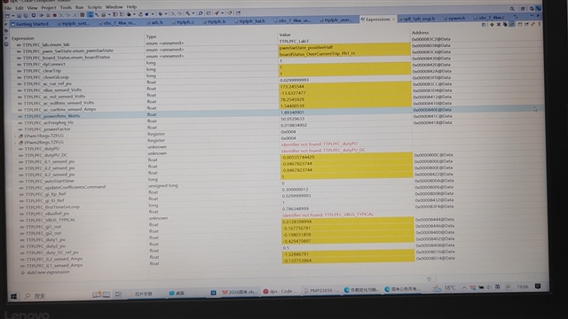
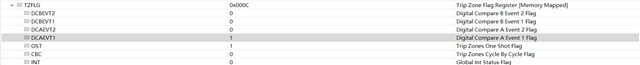
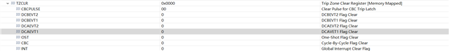
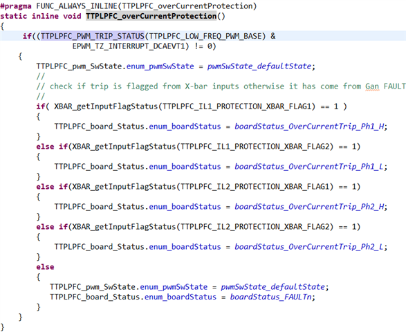
Regarding the overcurrent protection in Lab 3, when I run the program, it will enter the judgment condition of if((TTPLPFC_PWM_TRIP_STATUS(TTPLPFC_LOW_FREQ_PWM_BASE) & EPWM_TZ_INTERRUPT_DCAEVT1) != 0) and meet this condition, then proceed to execute the following program.
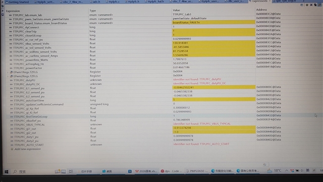
When the input voltage is 81V and the output voltage is 130V, the voltage is boosted but does not reach the expected level. The values of TTPLPFC_pwm_SwState.enum_pwmSwState and TTPLPFC_board_Status.enum_boardStatus are shown in the figure. Afterwards, the output voltage slowly drops to 81V multiplied by the square root of 2.
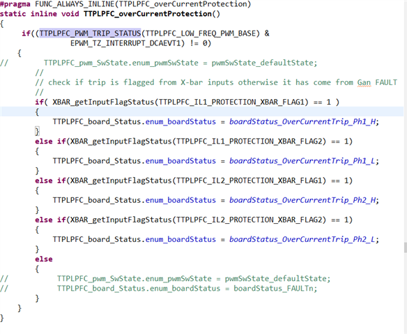
Subsequently, I commented out these two lines of code.

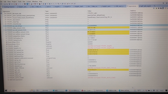
The values of TTPLPFC_pwm_SwState.enum_pwmSwState and TTPLPFC_board_Status.enum_boardStatus are shown in the figure.There is no voltage boost.
On this basis, I commented out the seventh line of code.
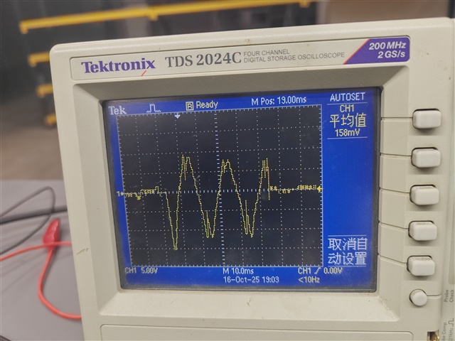
The output voltage reached 173V, which is the result of normal voltage boosting, but only momentarily. After that, the circuit board showed a PH-1-h overcurrent status, yet no current value exceeding the limit of 30A was observed in the monitoring window. Subsequently, the output voltage dropped slowly, but the circuit board continued to display the overcurrent status.