TPS25751: PP5V and sink question

Part Number: TPS25751


Question 1: PPHV corresponds to a bidirectional 5A current; PP5V corresponds only to the switch used when acting as a source to output externally. When TPS25751D is used as a source, can it only use the switch corresponding to PP5V to output 5V externally? Is it still possible to use the PPHV path to output power externally?


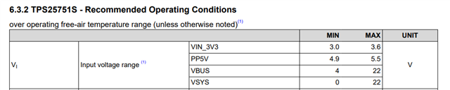
Question 2: When TPS25751D is used as a sink, it can only use the built-in bidirectional PPHV 5A switch. Are there any requirements for the input voltage and current? Does it have to be above 5V?


Question 3: TPS25751D needs to detect DCIN12V and a tablet (which does not support PD) insertion, both detections being based on GPIO high/low level. Can the results of this detection be used to switch the internal switches corresponding to PPHV or PP5V? Can the corresponding software adjustments accomplish this?


Question 4: Below is a preliminary block diagram of one of our ideas. Are there any suitable I2C bidirectional buck-boost chips you would recommend? Requirements: Input: 12V / ≥5A; Output: 5V~20V / Current ≥3A.Question


5: Does the EEPROM need to be of a specific model? Could you help recommend one? 


  • 已经收到了您的案例,调查需要些时间,感谢您的耐心等待。

  • Thank you for reaching out. I have a few preliminary questions about your system to help me understand the design requirements. 

    1. What is your company name?
    2. Will the TPS25751 be configured as dual role power (DRP)?
    3. What are all the sink and source PDOs that are required for the system?

    Down below are my answers to your questions:

    Question 1: PPHV or PP5V can be used to source the 5V from the PD controller. This can be modified within the Transmits source Capabilities Register in the Application Customization Tool. PP1 is PP5V and PP3 is PPHV. See image below.

    Question 2: You are correct that when the PD controller is sinking, the PPHV power path is used to output the required PDO. The TPS25751 can handle up to 20V/5A or 100W. Please see the table from the TPS25751 data sheet for the recommended inputs voltages.

    Question 3: I need a bit of clarification on the use case(s) for this to help answer this question.

    1. Will the detection of the DCIN12V and tablet be connected to the same GPIO or on separate GPIOs?
    2. Will the order of device connection be consistent? Specifically, will the DCIN12V always be connected first, followed by the tablet, or can the connection order vary?
    3. Why do you need to control the internal switches for PPHV and PP5V? These switches are designed to observe the needed power path depending on the current contract being negotiated, and they automatically adjust to ensure the correct power path is selected. Can you please clarify what specific requirements you have for controlling these switches?

    Question 4: I would suggest creating a new thread with the buck boost team to give you recommendations. 

    Question 5: For the TPS25751EVM, we use the CAT24C256 for the EEPROM.