TPS2663: Power Management IC for Energy Storage Systems: Power Path Device Selection

Part Number: TPS2663


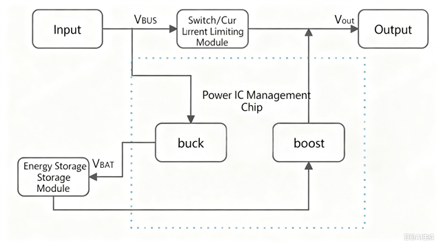
Hello, we aim to implement a hardware circuit system architecture similar to the block diagram below.

Using a 24 V bus, with an input power supply of 24 V/1.5 A. This system incorporates a lithium battery pack and power path management (power multiplexing) circuitry to implement a cooperative power supply strategy: “light loads powered by the adapter alone, heavy loads powered by the adapter + lithium battery in parallel.” This ensures stable, continuous operation of the 24 V output under peak 5 A (or 7 A) conditions (with continuous output lasting approximately 10 minutes within an hour).

1. Light Load Mode (Iout ≤ 1.5 A):

The adapter directly supplies the load while simultaneously charging the lithium battery pack via a Buck charger. Input power takes priority, with charging current limited by input surplus.

2. Heavy Load Mode (Iout = 5 A/7 A):

Under input power current-limiting protection (protection threshold 1.5 A), the battery supplies power in parallel with the adapter via the power path/buck-boost conversion (load sharing) to jointly maintain the 24 V bus. The adapter outputs continuously up to its current limit, while the battery compensates for the current gap.

  • Hello!

    We have received your case and will take some time. Thank you for your patience.

  • We are currently designing a power supply system where both the input and output voltages are 24V. The core requirement is to enable a ​24V DC adapter​ and a ​24V lithium battery pack​ to ​simultaneously supply power to the load​ in a coordinated manner, rather than simply switching between the two sources.

    A critical design constraint is that the input current drawn from the adapter front-end must ​never exceed 1.5A. Therefore, we require a power management solution capable of ​continuously monitoring and dynamically distributing​ the load current. This system must ensure that the current sourced from the adapter remains strictly below the 1.5A limit, with any deficit required by the load being supplemented ​seamlessly and in real-time by the battery pack.

    In essence, we need a ​Hybrid Power Path Management​ solution featuring ​​'Load Current Sharing'​​ functionality. Crucially, the adapter path requires ​true, dynamically adjustable current limiting​ (regulation), not just a simple over-current shutdown protection.

    Could you please advise if your company offers Power Management ICs (PMICs) that support these specific functions? Which product models would you recommend, and what are the key parameters we should focus on during our selection process?

    Thank you for your assistance. We look forward to your professional recommendations.

  • I don't see any block diagram.

    I think you want to implement something like below circuit. Current limit you can change dynamically by using DAC.

    check datasheet for more details on Priority MUX implementation.

  • I didn't see the picture you sent. Could you please describe it in words? Thank you!

  •  "Sorry! I had uploaded a block diagram elsewhere in the forum. Also, could you provide a detailed introduction on how to implement 'change dynamically by using DAC'?"