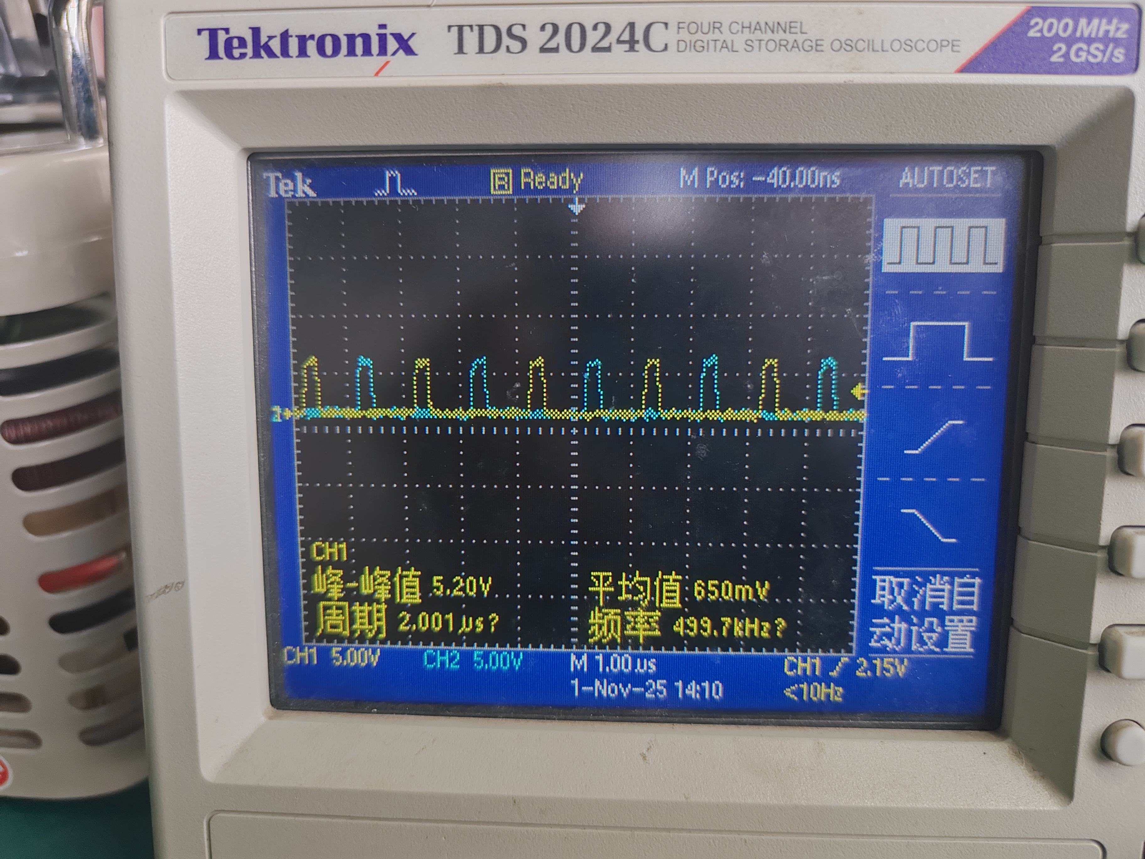
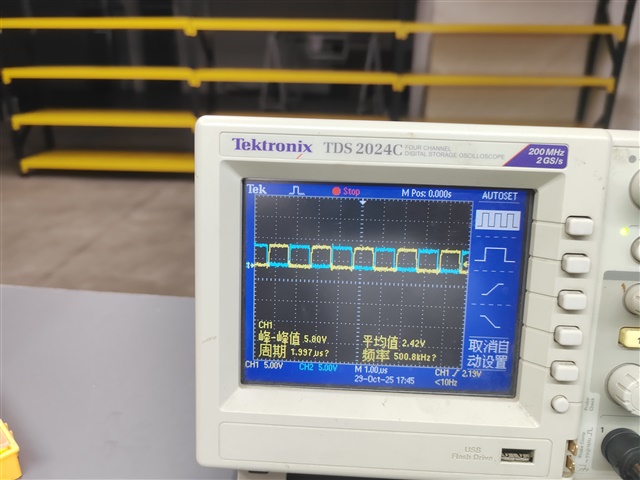
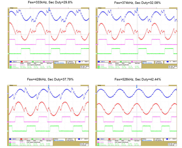
This image shows the PWM waveforms of the two lower arms on the secondary side. Is this duty cycle normal? Why is the duty cycle in the code multiplied by 2? From the observation of the waveforms, it seems more like the duty cycle is divided by 2.
//
//The following code should be used when the transformer polarity does not match the schematic.
//
// For secondary side the PWM is not centered around zero or period
// hence multiply by 2 (<<1) for period*duty
//
CLLLC_pwmDutyBSec_ticks = (uint32_t)((float32_t)CLLLC_pwmPeriod_ticks *
(float32_t)
(fabsf(CLLLC_pwmDutySec_pu))) << 1;
//
// for secondary side B ticks = period - duty_a
//
CLLLC_pwmDutyASec_ticks = (CLLLC_pwmPeriod_ticks) -
CLLLC_pwmDutyBSec_ticks;


