TIDM-02013: Regarding the Driving of CLLLC

Part Number: TIDM-02013


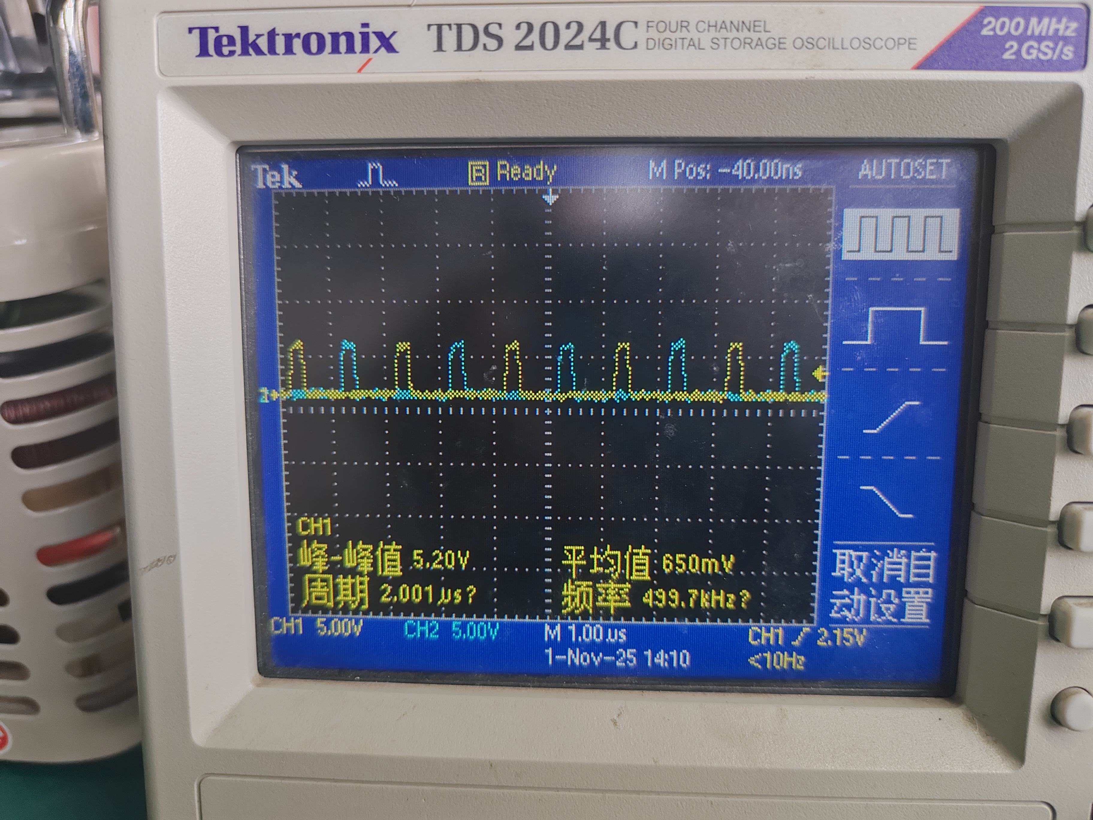
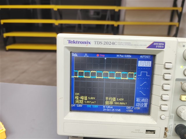
This image shows the PWM waveforms of the two lower arms on the secondary side. Is this duty cycle normal? Why is the duty cycle in the code multiplied by 2? From the observation of the waveforms, it seems more like the duty cycle is divided by 2. 

    //
    //The following code should be used when the transformer polarity does not match the schematic.
    //

    // For secondary side the PWM is not centered around zero or period
    // hence multiply by 2 (<<1) for period*duty
    //
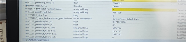
    CLLLC_pwmDutyBSec_ticks = (uint32_t)((float32_t)CLLLC_pwmPeriod_ticks *
                                      (float32_t)
                                      (fabsf(CLLLC_pwmDutySec_pu))) << 1;

    //
    // for secondary side B ticks = period - duty_a
    //
    CLLLC_pwmDutyASec_ticks = (CLLLC_pwmPeriod_ticks) -
                             CLLLC_pwmDutyBSec_ticks;

IMG_20251101_153927.jpg

  • Hi,

    We have received your post and the investigation will take some time. Thank you for your patience.

  • After the code runs, CLLLC_pwmDutySec_pu is 0.374879986. CLLLC_pwmDutyBSec_ticks = (CLLLC_pwmPeriod_ticks * (fabsf(CLLLC_pwmDutySec_pu))) << 1, and CLLLC_pwmDutyBSec_ticks equals 5886754. CLLLC_pwmDutyASec_ticks = (CLLLC_pwmPeriod_ticks) - CLLLC_pwmDutyBSec_ticks, and CLLLC_pwmDutyASec_ticks equals 1964766. According to the calculation, the PWM waves of the two lower switches in the secondary-side bridge arm should be complementary, but the actual measurement shows otherwise. As shown in the figure, the PWM waves of the two lower switches in the primary side are complementary.

    If the driving of the secondary side is set correctly, I will then conduct Experiment 2 to detect the operating status during open-loop operation.

  • The reason for this is  mentioned in the comments of the code snippet you shared "For secondary side the PWM is not centered around zero or period" as compared with primary side (PWM is centered around zero). I have highlighted that in in below diagram.

  • Okay, I understand what you mean. However, according to the formula calculation, in real-time display, CLLLC_pwmDutySec_pu = 0.375, but in actual measurement, the duty cycle is approximately 0.125.What is the reason for this?
    From the formula:CLLLC_pwmDutySec_pu = (0.45f + CLLLC_pwmDutySecAdjust_pu)-(CLLLC_pwmPhaseShiftPrimSec_ns * ONE_NANO_SEC * CLLLC_pwmFrequency_Hz)-CLLLC_pwmPhaseShiftPrimLegs_pu;
    it can be seen that as the frequency increases, the duty cycle decreases. But according to the experimental manual, the higher the frequency, the larger the duty cycle.

    The duty cycles of the two secondary bridge arms are determined by CLLLC_pwmDutyASec_ticks or CLLLC_pwmDutyBSec_ticks? According to the experimental manual and observations of the actually measured duty cycles, the duty cycles are not in a complementary relationship.
    CLLLC_pwmDutyASec_ticks = (CLLLC_pwmPeriod_ticks) - CLLLC_pwmDutyBSec_ticks;

    Another point is: Is a Rogowski coil necessary for this circuit? Does the presence of the Rogowski coil only serve to facilitate observing the resonant current on an oscilloscope, without playing any role in the code?