Part Number: BQ40Z80
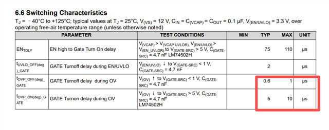
Other Parts Discussed in Thread: LM74502
1. This issue does not occur when VBAT is low. However, when VBAT exceeds 24V, the likelihood of failure increases dramatically.
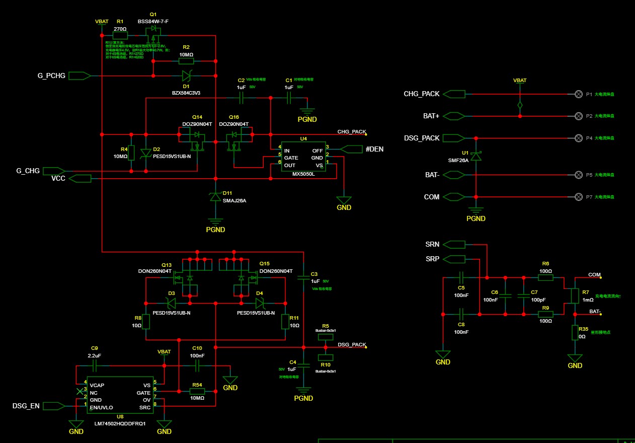
2. I suspect this is caused by input capacitance (Cin) on the board, which—during power-up—creates a resonant condition leading to voltage overshoot that destroys the chip. During debugging, I reduced Cin from 3 µF to 300 nF and added a 3.9 Ω resistor in series at the capacitor input. This nearly eliminated the visible spark during power-up, yet the chip still failed, and the "failure threshold voltage" did not increase.
3. The board actually includes a TVS diode (SMF26A), with its cathode tied to VCC and anode to GND. In theory, because the charge/discharge MOSFETs have body diodes, any voltage spikes originating from either the battery or the CHG_PACK line should be clamped by this TVS.
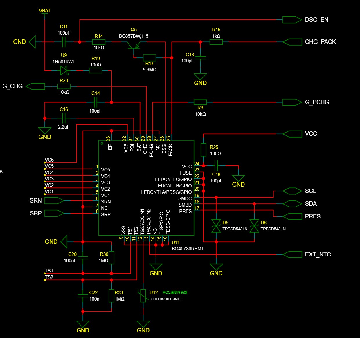
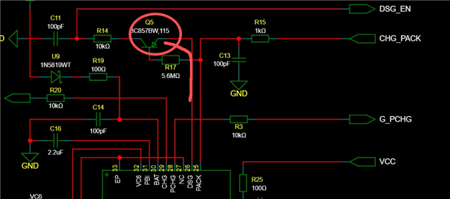
Schematic diagram (partial):


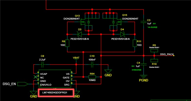 这个LM74502 芯片使用效果怎么样,我看它的从检测到上升、下降包括延时的时间非常短,真驱动真有这么强吗?