Part Number: TPS923652
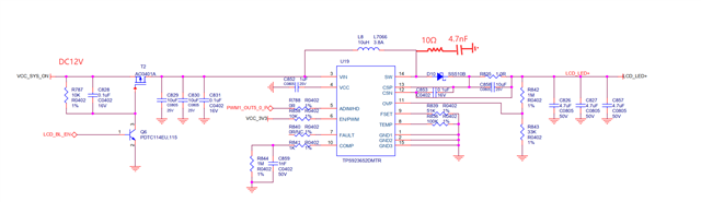
It is designed to drive a 24V 0.4A high-brightness screen.
The frequency is set at 400KHZ, and the MCU is used to send a 10KHZ PWM signal to the ADIM PIN as analog dimming.
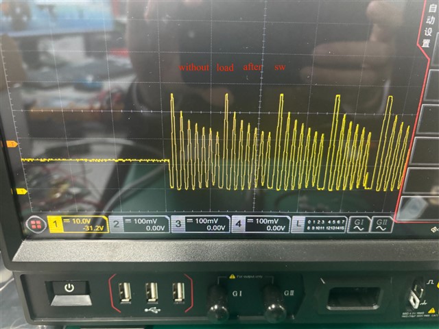
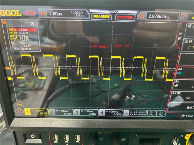
During the testing process, TPS923652 was occasionally damaged.
We designed it in mid-2024. In the latest data manual, we found that CSN and CSP have a set of RC.
Datasheet says it is optional and is for noise filtering purpose.
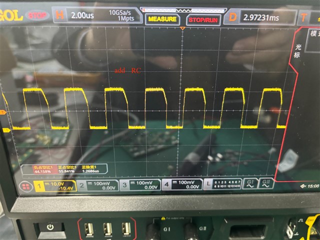
However, we didn't reserve a position for R, so we came up with an alternative solution. We pulled down a set of R+C to ground at the SW end. The resistance of R is 10 ohms, and the capacitance of C is 4.7nF. So far, no damage has occurred during testing. Could this also solve the damage issue?Or is there any risk associated with this RC?