This thread has been locked.

If you have a related question, please click the "Ask a related question" button in the top right corner. The newly created question will be automatically linked to this question.

LM3409HVEVAL: Driving issue of the EN pin for the LM3409

Part Number: LM3409HVEVAL
Other Parts Discussed in Thread: LM3409

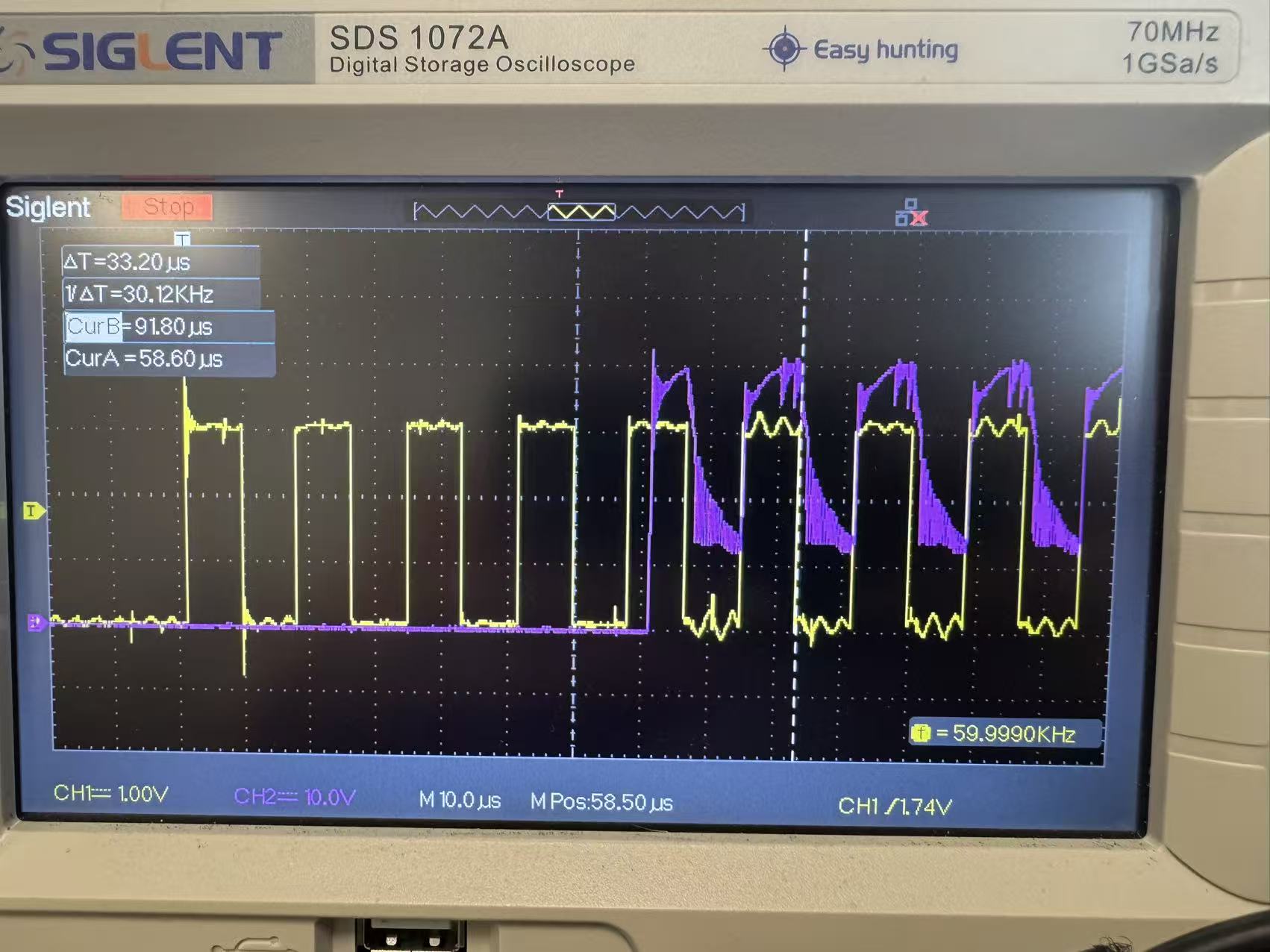
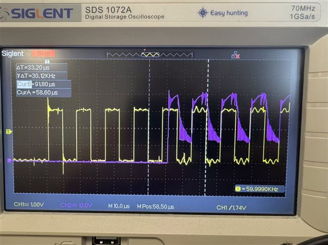
Hello, I have the following questions regarding the use of the **LM3409**. Currently, dimming is implemented via the **EN pin**: 1. The yellow waveform is the **EN pin voltage**, and the purple waveform is the **load voltage**. When the EN pin is activated, there is no output for the first few cycles, and there is a large delay before the first output appears. After that, it returns to synchronization. What is the reason for this, and how can it be fixed? 2. When dimming using the EN pin, there is a  2 μs delay during turn-off. How can I reduce this delay? e628860ea36ed9f499d9c4b1d3e91726.jpg

  • Hello, we have received your case and the investigation will take some time. Thank you for your patience.

  • Please refer to datasheet for detailed information 

    WIth ENABLE control, Inductor current rises from 0 to target current, accordingly, Vout ramps from 0 to VF to deliver full ILED current. 

    If you expect high slew rate PWM dimming, you can consider shunt dimming solution, refer to datasheet: 

    8.3.8 External Parallel FET PWM Dimming

  • i have two question,i hope each one can get a answer。And External PWM Dimming is higher temperature rise than EN mode Dimming;

  • I've already answered to the questions above. Please kindly read details in 8.3.6 PWM Dimming Using the EN Pin  & 8.3.8 External Parallel FET PWM Dimming to better understand the two dimming modes and their differences. 

    Yes  that External PWM Dimming is higher temperature rise than EN mode Dimming as inductor current keeps flowing during PWM off. It's trade off between dimming speed/linearity and efficiency. 

  • I think your answer has solved problem 2 but not problem 1;Can you see this picture? The yellow one is the dimming waveform output by the EN pin, and the purple one is the working voltage of the load. Under the input of the first few EN pin pulses, the load has no output. It is not until the fifth pulse comes that the load has an output, but it is not synchronized with the EN pulse. The sixth pulse is synchronized. This situation occurs every time the input pulse of the EN pin stops for a period of time (approximately 1 second) and then is re-input.I want to know the specific reason. Thank you very much.