Part Number: UCC256404
Other Parts Discussed in Thread: UCC24624, UCC28056
Dear TI Technical Support Team,
Hello! I am currently designing a half-bridge LLC resonant converter using the UCC256404B controller, the UCC28056B PFC controller, and the UCC24624 synchronous rectifier driver. During simulation and design, I have encountered several critical issues and would greatly appreciate your professional guidance.
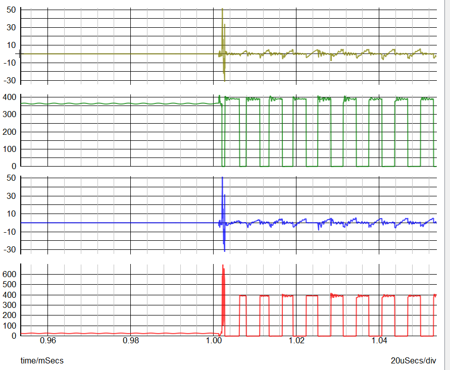
First, regarding MOSFET current and voltage spikes at startup: In simulation, when using MOSFET models, I observed large current and voltage spikes on the primary-side MOSFETs at the moment of startup. Adding a small amount of parasitic inductance does not eliminate these spikes. After reviewing relevant materials, I suspect the issue is caused by the MOSFETs' initial parasitic capacitance being zero and hard switching. Is there a solution for this?
Second, regarding soft start and output voltage overshoot: I am facing a dilemma with the soft start implementation. Increasing the soft start capacitor value to slow down the voltage ramp‑up causes severe output voltage overshoot. Adjusting the feedback loop parameters to suppress the overshoot then introduces loop stability problems. Is there a way to solve both issues simultaneously?
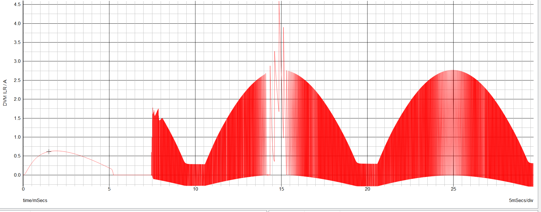
Third, regarding the UCC28056 startup issue: Sometimes, due to a small voltage difference during startup, the UCC28056 enters CCM mode, which creates an inductor current spike. How can this problem be resolved?
Fourth, regarding integrated simulation of multi‑controller designs: My design uses three separate ICs (UCC256404B, UCC28056B, UCC24624), each with its own simulation model. I would like to simulate the complete system in the same environment to verify end‑to‑end performance. Is it possible to place the three model files into the same project? If so, how should I do it?
Thank you for your time and support. I look forward to your reply.