If you have a related question, please click the "Ask a related question" button in the top right corner. The newly created question will be automatically linked to this question.
Could you please clarify the exact problem you are seeing? Can you share a log file of this behavior so I can see the instability over time?
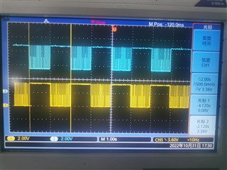
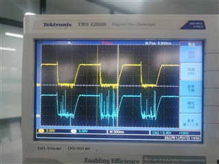
From the image captures you have included in your original post, it looks like the top of stack cell voltage is measuring lower than the other cell voltages. This can be caused when too many cells are balancing at the same time, which increases current flow into the top cell input. This leads to a greater IR drop across the cell input resistor, potentially causing voltage measurement errors. To address this, you could use a 20 Ω resistor on the VC16 pin to reduce the IR drop while using 100 Ω on the other pins. Although this may not be your main issue, it could make the voltage problems you are seeing worse.
Section 2.5 Voltage Measurement Accuracy During Balance in the Cell Balancing with BQ769x2 Battery Monitors application note has more information on the issue I explained above, as well as other cell balancing considerations. I will link it here: Cell Balancing With BQ769x2 Battery Monitors (Rev. A) (ti.com).
Some other notes worth considering:
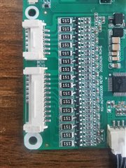
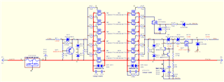
The base resistors you are using on the cell balancing BJTs have a high value. 240 Ohms is recommended in the app note. If the base resistor value is too high, this can limit balanicng current.
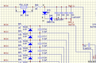
There are Zener diodes between the cell input pins (ZD26, ZD27, ...) What are their values? They can cause issues during balancing because they might not allow the voltages to pull to the correct levels during balancing. If they are 6.8V Zeners, then that is okay.
The Cell Balance Min Delta and Cell Balance Stop Delta parameters are very small (2mV and 1mV) - I do not recommend setting these values so low or the device will always be balancing.
The Sleep settings are strange - Sleep is disabled in the Power Config register, but the DSG FET is set to go into source follower mode in sleep in the Chg Pump Control register. The Sleep Current setting (20mA) is much higher than the Dsg Current Threshold and Chg Current Threshold settings (10mA).
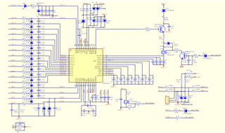
The connections BC0 to Q40 base, BC1 to Q39 base, BC2 to Q38 base make sense, but why are there connections from BAT0-R80 to Q40, BAT1-R79 to Q39, BAT2-R61 to Q38, etc.? Can they try removing R80, R79, R61, ...?
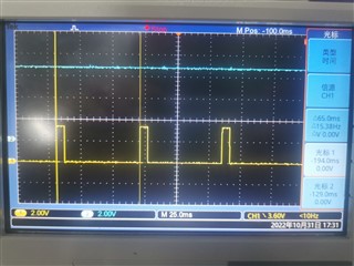
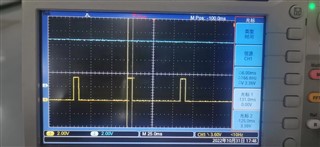
The voltage measurements will not be different after enabling cell balance. Cell balancing is paused each time a voltage measurement occurs - you can see waveforms in the cell balancing application report showing this duty cycle.
When you test cell balancing, you should use real cells. Cell balancing with the EVM resistor divider will not be stable and will cause the overvoltage alert to trigger which will disable balancing.
I did not see anything obvious on the schematic for the charge pump, but what is the circuit shown between the DSG pin and PACK+, is it a speed-up circuit?
I see that C51 is not connected anywhere. I also notice that there is no sense resistor in the schematic. The REGIN C46 should be 22-nF. The LD/PACK resistors also seem very large.
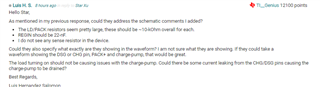
The BQ76952 device draws its supply current from the BAT pin, which is typically connected to the top of stack point through a series diode, to protect against any fault within the device resulting in unintended charging of the pack. A series resistor and capacitor is included to lowpass filter fast variations on the stack voltage. During a short circuit event, the stack voltage may be momentarily pulled to a very low voltage before the protection FETs are disabled. In this case, the charge on the BAT pin capacitor will temporarily support the BQ76952 device's supply current, to avoid the device losing power.
D39 is important to keep the BAT pin voltage from being pulled low during a very heavy load like a short-circuit event. However, F10 should not be in parallel with D39 and R66 should be 100 ohms since this is part of the filter for the BAT pin.
RF1 should be at least 20 Ohms which is the minimum allowed cell input resistor by the datasheet specification.