1. When the chip is powered on, the BLANK is directly pulled up, and some pins still have outputs (at this time, the program has no control).
2. Use the program to drive the IC, and the IC output does not change at all, as it did at the initial power on.
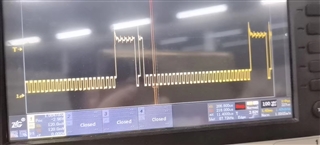
3. The MCU driver waveform is very strange(SCLK).
#define SCLK(x)		GPIO_Output(GPIOC,GPIO_Pin_8,x);//移位时钟,上升沿移位
#define SIN(x)		GPIO_Output(GPIOC,GPIO_Pin_7,x);//串行数据
#define XLAT(x)		GPIO_Output(GPIOC,GPIO_Pin_6,x);//上升沿时数据移到锁存器
#define BLANK(x)	GPIO_Output(GPIOD,GPIO_Pin_15,x);//为高时关闭输出,底时按时序控制


/*GSdata[] is for GS register*/
int GSdata[]={
                0x0000,0x0000,0x0000,   //D0 B,G,R
                0x0000,0x0000,0x0000,   //D1 B,G,R
                0x0000,0x0000,0x0000,   //D2 B,G,R
                0x0000,0x0000,0x0000,   //D3 B,G,R
                0x0000,0x0000,0x0000,   //D4 B,G,R
                0x0000,0x0000,0x0000,   //D5 B,G,R
                0x0000,0x0000,0x0000,   //D6 B,G,R
                0x0000,0x0000,0x0000,   //D7 B,G,R

                0x0000,0x0000,0x0000,   //D8 B,G,R
                0x0000,0x0000,0x0000,   //D9 B,G,R
};

/*GS_Iter[] is for GS register iteration in breathing mode*/
int GS_Iter[]={0,1,1,1,1,1,2,2,2,3,3,3,4,4,4,5,5,5,6,6,7,7,8,8,9,9,10,10,11,11,12,12,13,14,15,16,17,18,20,
                 21,23,25,26,28,30,32,34,36,38,40,43,45,48,50,53,56,59,62,65,68,71,75,78,82,85,89,93,97,
                 101,105,110,114,119,123,128,133,138,143,149,154,159,165,171,177,183,189,195,202,208,215,
                 222,229,236,243,250,258,266,273,281,290,298,306,315,324,332,341,351,360,369,379,389,399,
                 409,419,430,440,451,462,473,485,496,508,520,532,544,556,569,582,594,608,621,634,648,662,
                 676,690,704,719,734,749,764,779,795,811,827,843,859,876,893,910,927,944,962,980,998,1016,
                 1034,1053,1072,1091,1110,1130,1150,1170,1190,1210,1231,1252,1273,1294,1316,1338,1360,1382,
                 1404,1427,1450,1473,1497,1520,1544,1568,1593,1617,1642,1667,1693,1718,1744,1770,1797,1823,
                 1850,1877,1905,1932,1960,1988,2017,2045,2074,2103,2133,2162,2192,2223,2253,2284,2315,2346,
                 2378,2410,2442,2474,2507,2540,2573,2606,2640,2674,2708,2743,2778,2813,2849,2884,2920,2957,
                 2993,3030,3067,3105,3143,3181,3219,3258,3297,3336,3376,3416,3456,3496,3537,3578,3619,3661,
                 3703,3745,3788,3831,3874,3918,3962,4006,4010,4015};

void SendData(int *temp)
{
	int i,temp1,temp2;

	BLANK(1);

	for(i=287;i>0;i--)//288
	{
		temp1=1<<(i%12);
		temp2=temp[i/12]&temp1;

		if(temp2==temp1){SIN(1);}
		else {SIN(0);}

		SCLK(0);
		delayus(200);
		SCLK(1);//上升沿
		delayus(200);
		WWDG->CR = 0x7e & WWDG_CFGR_WINDOW;
	}

	SCLK(0);

	XLAT(1);//上升沿移入锁存器
	delayus(200);
	XLAT(0);//
	delayus(200);

	BLANK(0);
}

/*LED_Set is used to set LED RGB GS data*/
void LED_Set(int Num,int GS_Red,int GS_Green,int GS_Blue)
{
    GSdata[Num*3]=GS_Blue;
    GSdata[Num*3+1]=GS_Green;
    GSdata[Num*3+2]=GS_Red;
}


void Ini_Red(void)
{
    int i;
    for(i=0;i<8;i++)
    {
        LED_Set(i,0,0,4000);
    }
    SendData(GSdata);
}

void main(INT8U *dat)
{
	//LED输出-BLANK
	GPIO_InitStructure.GPIO_Pin  = GPIO_Pin_15;
	GPIO_InitStructure.GPIO_Mode = GPIO_Mode_Out_PP;
	GPIO_Init(GPIOD, &GPIO_InitStructure);
	GPIO_Output(GPIOD,GPIO_Pin_15,1);
	//LED输出-XLAT
	GPIO_InitStructure.GPIO_Pin  = GPIO_Pin_6;
	GPIO_InitStructure.GPIO_Mode = GPIO_Mode_Out_PP;
	GPIO_Init(GPIOC, &GPIO_InitStructure);
	GPIO_Output(GPIOC,GPIO_Pin_6,0);
	//LED输出-SIN
	GPIO_InitStructure.GPIO_Pin  = GPIO_Pin_7;
	GPIO_InitStructure.GPIO_Mode = GPIO_Mode_Out_PP;
	GPIO_Init(GPIOC, &GPIO_InitStructure);
	GPIO_Output(GPIOC,GPIO_Pin_7,0);
	//LED输出-SCLK
	GPIO_InitStructure.GPIO_Pin  = GPIO_Pin_8;
	GPIO_InitStructure.GPIO_Mode = GPIO_Mode_Out_PP;
	GPIO_Init(GPIOC, &GPIO_InitStructure);
	GPIO_Output(GPIOC,GPIO_Pin_8,1);

	while(1)
	{
		Ini_Red();
	}
}