This thread has been locked.
If you have a related question, please click the "Ask a related question" button in the top right corner. The newly created question will be automatically linked to this question.
实验过程:
1、电池连接逆变器,逆变器带负载进行40A电流放电实验;
2、当电池发生故障时,MCU向BQ下发切断充放电MOS命令,然后控制DFETOFF(配置成关闭充放电MOS),进行关闭,并使BQ进入SHUTDOWN 模式,电池输出关闭了;
3、电池再次开机,电池再无输出。
初步检查:
1、读取Alarm Raw Status寄存器,解析数据为充放电MOS处于闭合状态;
2、读取0x68寄存器,解析数据 BQ内部温度为0xD0C;
3、断开BQ的DSG和CSG外部电路,测量DSG和CSG引脚电压,分别为0.1V和2.7V;
4、测量BQ的PDSG输出为10V;
5、其中BQ读取到的单体电压和温度是正常值
期望:
1、分析BQ寄存器指示充放MOS闭合,但DSG和CSG为什么没输出?
2、电池进行带载荷(有电流)切断时的注意点;
3、发生以上故障的真正原因。
亟待解决,非常感谢。
我们判断是BQ的MOS控制引脚被损坏或者是BQ被锁死无法输出电压来闭合FET
Part Number: BQ76952
实验过程:
1、电池连接逆变器,逆变器带负载进行40A电流放电实验;
2、当电池发生故障时,MCU向BQ下发切断充放电MOS命令,然后控制DFETOFF(配置成关闭充放电MOS),进行关闭,并使BQ进入SHUTDOWN 模式,电池输出关闭了;
3、电池再次开机,电池再无输出。
初步检查:
1、读取Alarm Raw Status寄存器,解析数据为充放电MOS处于闭合状态;
2、读取0x68寄存器,解析数据 BQ内部温度为0xD0C;
3、断开BQ的DSG和CSG外部电路,测量DSG和CSG引脚电压,分别为0.1V和2.7V;
4、测量BQ的PDSG输出为10V;
期望:
1、分析BQ寄存器指示充放MOS闭合,但DSG和CSG为什么没输出?
2、电池进行带载荷(有电流)切断时的注意点;
3、发生以上故障的真正原因。
亟待解决,非常感谢。
Part Number: BQ76952
实验过程:
1、电池连接逆变器,逆变器带负载进行40A电流放电实验;
2、当电池发生故障时,MCU向BQ下发切断充放电MOS命令,然后控制DFETOFF(配置成关闭充放电MOS),进行关闭,并使BQ进入SHUTDOWN 模式,电池输出关闭了;
3、电池再次开机,电池再无输出。
初步检查:
1、读取Alarm Raw Status寄存器,解析数据为充放电MOS处于闭合状态;
2、读取0x68寄存器,解析数据 BQ内部温度为0xD0C;
3、断开BQ的DSG和CSG外部电路,测量DSG和CSG引脚电压,分别为0.1V和2.7V;
4、测量BQ的PDSG输出为10V;
5、其中BQ读取到的单体电压和温度是正常值
期望:
1、分析BQ寄存器指示充放MOS闭合,但DSG和CSG为什么没输出?
2、电池进行带载荷(有电流)切断时的注意点;
3、发生以上故障的真正原因。
亟待解决,非常感谢。
我们判断是BQ的MOS控制引脚被损坏或者是BQ被锁死无法输出电压来闭合FET
读取 Safety Alert A 值为0x00
读取 Safety Status A 值为0x00
读取 Safety Alert B 值为0x00
读取 Safety Status B 值为0x00
读取 Safety Alert C 值为0x00
读取 Safety Status C 值为0x00
读取 PF Alert A 值为0x00
读取 PF Status A 值为0x00
读取 PF Alert B 值为0x00
读取 PF Status B 值为0x00
读取 PF Alert C 值为0x00
读取 PF Status C 值为0x00
读取 PF Alert D 值为0x00
读取 PF Status D 值为0x00
读取 电池状态 值为0x80
读取 Stack Voltage 值为0x12BD
读取 PACK Pin Voltage 值为0x0014
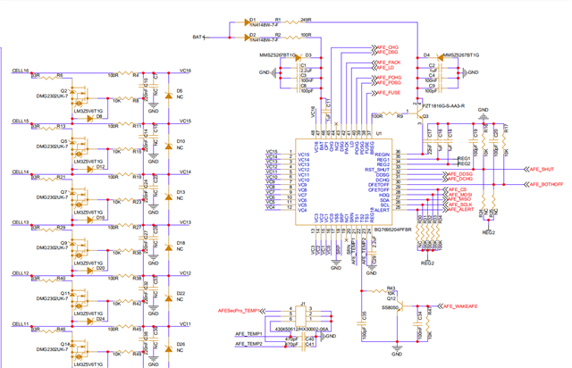
读取 LD Pin Voltage 值为0x0013SCHEMATIC1 _ P04_FETDrive.pdf
读取 Alarm Raw Status 值为0x0683
读取 内部温度 值为 0x0CEE
您好,请参考下面内容
Could you check 0x0057 MANUFACTURINGSTATUS [FET_EN] to see if it is low? If it is low then sending the FET_ENABLE() command will set that bit high and bring the device out of FET Test Mode.
It's worth noting that exiting SHUTDOWN mode will cause the device to reload its default or OTP programmed register settings. If any changes to the register settings were made before entering SHUTDOWN mode, they will not persist after exiting SHUTDOWN mode unless they are programmed into the OTP.
您好,请参考下面内容
Were any abs max ratings exceeded on the device? Have there been multiple IC failures with this design or has this occurred with just one IC?
Also, I recommend taking a look at Figure 5-2 of the Multiple FETs app note. D4 and D5 on that schematic are necessary for the BJTs that you use in your schematic to turn on properly.
你们是否可以提供现场支持
如果需要现场支持请联系TI FAE,非常抱歉我这里查不到联系方式。