

Part Number: LMQ61460-Q1
I referenced both "Minimizing Buck-Boost (Inverting) Converter High-Frequency Switching Noise"(https://www.ti.com.cn/cn/lit/pdf/slva219) and "Working With Inverting Buck-Boost Converters"(https://www.ti.com/lit/an/snva856b/snva856b.pdf) articles.
But I don't know how to properly add an RC snubber circuit under Inverting Buck Boost application.
I learned about the location of adding the RC snubber circuit for Boost from article (https://www.ti.com.cn/cn/lit/pdf/zhca057).
I learned about the location of adding the RC snubber circuit for Buck from article (https://www.ti.com.cn/cn/lit/pdf/zhcaa52).
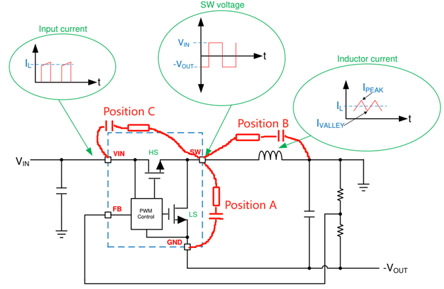
Which of the positions A, B, and C in the above figure is the correct placement position for the RC snubber circuit in the Inverted Buck Boost application?
Very much looking forward to and thank you for your response!
