


Part Number: TPS25750
Hey,
We have created a bin file that can be written to EEPROM using USBCPD_application_Customization Tool. After entering the file, when we first insert the battery and then insert the USB PD charger, there will be no current at the USB PD charger, only voltage, as shown in the figure 1.
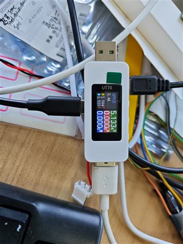
fig. 1
When we first insert the USB PD charger and then insert the battery, the battery will resume charging, as shown in Figure 2.
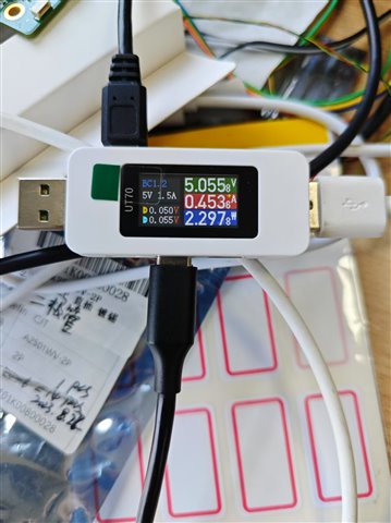
fig. 2
Another issue is that after the battery is charged, the charging protocol does not seem to charge according to the USB PD protocol. From the content shown in Figure 1 and Figure 2, the charging type is APPLE2.4 or BC1.2 (both situations may occur). But when we use a USB tester for testing, we can find that the configured charging protocol is USB PD, as shown in Figure 3.
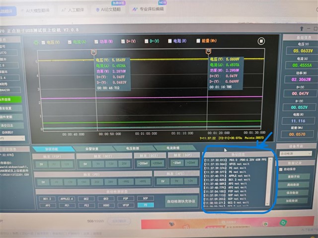
fig. 3
However, when we attempt to change the output mode to PD and raise the voltage to 9V, the battery will no longer charge, as shown in Figure 4.
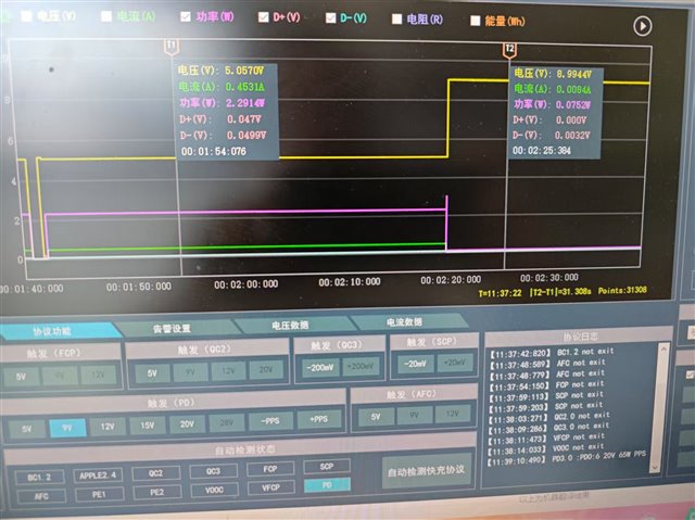
fig. 4
The circuit diagram of TPS25750 is shown in Figure 5 and Figure 6, and the circuit diagram of BQ25792 is shown in Figure 7. We believe that the probability of TPS25750 configuration errors is higher. When the device is connected to the battery but not to the charger and the BQ25792 module ADC register is opened through I2C, we found that the values are normal except for the input voltage. However, when the USB PD charger is inserted, the input voltage is still 0. In addition, when we tried to directly connect TYPE-C input to BQ25792 and found that this was feasible in a short period of time, but it caused severe overheating.
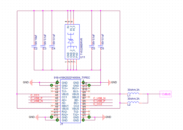
Fig.5
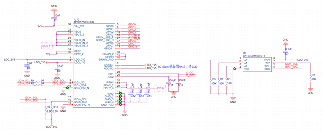
Fig.6
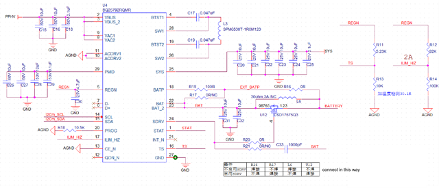
Fig.7
The overall problem can be summarized as follows:
- When the module is connected to the battery first and then to the USB PD charger, the module will encounter a problem of not being able to charge. Is it a configuration issue with the bin file generated by us using USBCPD_application_Customization Tool? If that's the case, how should we configure it? Or should I use I2Cs to configure TPS25750?
- When the module is configured to charge in USB PD mode, the charging method is not USB PD. Is there a configuration issue with the bin file generated by us using USBCPD_application_Customization Tool? If that's the case, how should we configure it?
The bin file and json file configured by USBCPD_application_Customization Tool are attached.
Thank you very much.
{
  "questionnaire": {
    "device": "TPS25750",
    "toolBuildVersion": "1.0.2",
    "answers": [
      null,
      4,
      4,
      3,
      1,
      0,
      3,
      0,
      1,
      1,
      0,
      12.6,
      2,
      0.4,
      0.4
    ],
    "vendorId": "0000",
    "productId": "0000",
    "version": "1.0.0.2"
  },
  "configuration": {
    "data": {
      "selected_ace": [
        {
          "register": 6,
          "data": [
            0,
            0,
            0,
            0,
            0,
            0,
            0,
            0
          ]
        },
        {
          "register": 22,
          "data": [
            10,
            48,
            48,
            77,
            0,
            0,
            0,
            0,
            0,
            0,
            3
          ]
        },
        {
          "register": 50,
          "data": [
            0,
            168,
            42,
            44,
            145,
            1,
            38,
            44,
            209,
            2,
            0,
            44,
            177,
            4,
            0,
            244,
            65,
            6,
            0,
            0,
            0,
            0,
            0,
            0,
            0,
            0,
            0,
            0,
            0,
            0,
            0
          ]
        },
        {
          "register": 51,
          "data": [
            4,
            44,
            145,
            1,
            16,
            44,
            209,
            2,
            0,
            44,
            177,
            4,
            0,
            44,
            65,
            6,
            0,
            69,
            65,
            6,
            0,
            0,
            0,
            0,
            0,
            0,
            0,
            0,
            0
          ]
        },
        {
          "register": 92,
          "data": [
            127,
            0,
            0,
            0,
            0,
            0,
            0,
            0,
            0,
            16,
            0,
            0,
            0,
            0,
            0,
            0,
            48,
            0,
            0,
            0,
            0,
            0,
            0,
            0,
            0,
            12,
            0,
            0,
            0,
            0,
            0,
            0,
            0,
            0,
            0,
            0,
            7,
            8,
            9,
            10,
            0,
            0,
            1,
            0,
            0,
            0,
            0,
            0,
            0
          ]
        },
        {
          "register": 117,
          "data": [
            0,
            0,
            0,
            0
          ]
        }
      ]
    }
  }
}
