TMS320C5515: TMS320C5515: The CSL_USB_MSC_dmaExample example cannot run when downloaded to the development board

Part Number: TMS320C5515

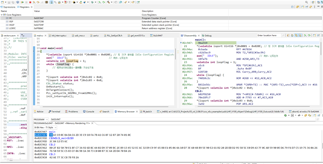
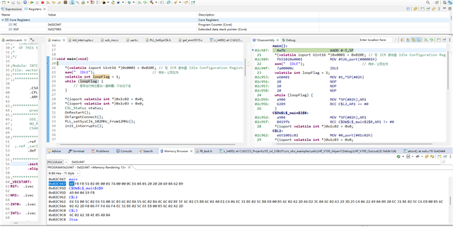
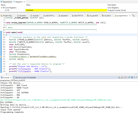
I downloaded the CSL_USB_MSC_dmaExample_Out.bin file generated by hex55.exe to the IIC EEPROM on the control board with the TMS320C5515 chip as the processor using the programmer_c5515evm_ccs4 program, but the program does not run as expected, although it runs correctly during debug.
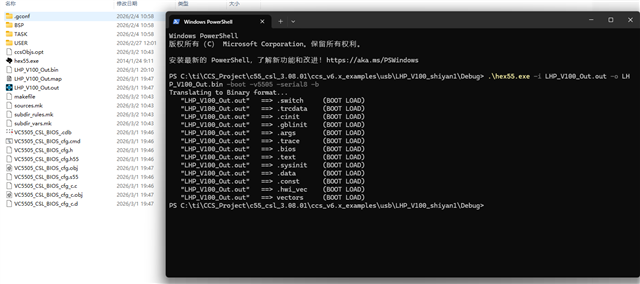
The command I entered using hex55.exe is as follows

.\hex55.exe -i CSL_USB_MSC_dmaExample_Out.out -o CSL_USB_MSC_dmaExample_Out.bin -boot -v5505 -serial8 -b

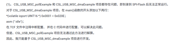
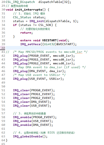
I noticed that a post described this issue as follows:

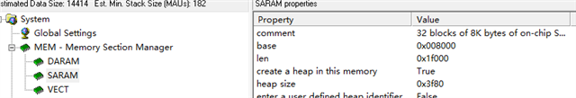
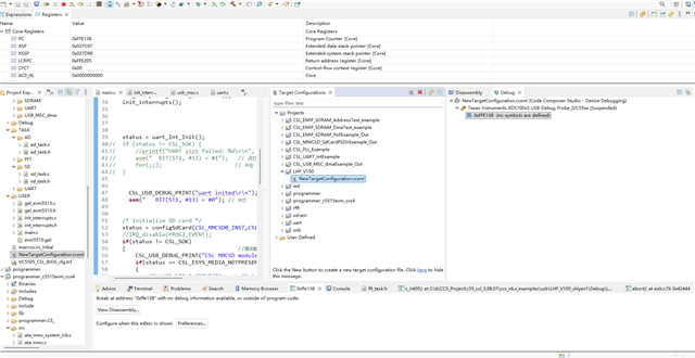
Therefore, I changed the positions of SARAM and the interrupt vector table in the TCF file, as shown in the figure. 

image.pngimage.png

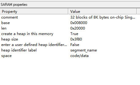
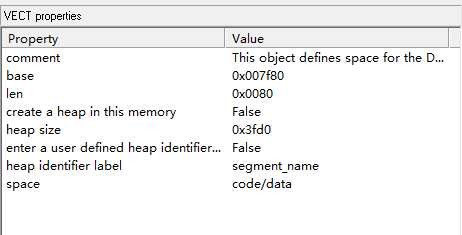
But it still doesn't work. After downloading it, it still doesn't start. Could it be that I configured it incorrectly, or is there some other issue I haven't solved?

  • Hi,

    We have received your post and the investigation will take some time. Thank you for your patience.

  • According to the sprabd7d.pdf:

    SARAM31 (byte address 0x4E000 – 0x4FFFF) is reserved for the bootloader.

    Make sure your application program is not using this memory area.

    Another thing is the C5515/14/05/04 has a fixed order in which it checks for a valid boot-image on each supported boot device. The device order is NOR Flash, NAND Flash, 16-bit SPI EEPROM, I2C EEPROM, and MMC/SD. The first device with valid boot-image is used to load and execute user code. Make sure there is no boot image in NOR Flash, NAND Flash, 16-bit SPI EEPROM (boot devices before I2C EEPROM).

    Best regards,

  • But I allocated the SARAM memory space as: 0x10000-0x4E000, excluding SARAM31, and the program still doesn't start. Additionally, my development board doesn't have NOR Flash, NAND Flash, or 16-bit SPI EEPROM storage peripherals. Could there be other hidden bugs in this example? I really can't figure out why this example debugs without issues but still fails to start. Other examples can start up normally, such as the CSL_UART_IntExample (which doesn't include the BIOS operating system). Could you try running this example?

    Additionally, I found a post on a Chinese forum about how to solve this problem, as shown in the picture below. I tried the method shown in the picture, but I still didn't succeed. My interrupt configuration code is shown in the picture below, but I still didn't succeed. Therefore, I really can't find what the issue is. I'm asking for help from TI experts to see if this problem can be solved.

  • Hello,

    // enable the MPORT and disable HWA
    *(volatile ioport Uint16 *)0x0001 = 0x020E;
    asm(" idle");

    is used to enable the M-PORT which was disabled by the ROM bootloader. MPORT is used by the USB CDMA.

    To identify where your flashed image went wrong, you can add the following code at the beginning of your main():

    int loopFlag = 1;

    while (loopFlag)

    {

    }

    After you run your application, then you use JTAG to halt the DSP (without using GEL file). You should be at the while loop. If you change the loopFlag to 0, then you can single step through your code. Start with the debug version. With load symbol from the *.OUT file, you should be able to do the source code single step.