

Other Parts Discussed in Thread: TCA6424
EVM: J721EXCP01EVM
SDK: ti-processor-sdk-rtos-j721e-evm-08_06_01_03
Refer: mcan_evm_loopback_app_main_k3.c
在 J721EXCP01EVM 打算使用
(MCU1_0) MCU MCAN0 – J30 (J29)
(MCU2_1) Main MCAN0 – J27 (J24)
目前設定Main MCAN0時候,IO Expander (TCA6424) 都會發生卡在下列設定。
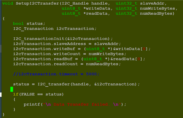
當使用 I2C_transfer() 無法 return value到 status,程序 hang 在這邊。
想請問是設定TCA6424 時候,周邊沒有搭配好嗎? 或是發生問題!? 謝謝。
void padConfig_prcmEnable()
{
/* UART Init */
Board_initCfg boardCfg;
Board_STATUS boardStatus;
I2C_Params i2cParams;
I2C_Handle handle = NULL;
uint8_t dataToSlave[4];
boardCfg = BOARD_INIT_MODULE_CLOCK |
BOARD_INIT_PINMUX_CONFIG;
boardStatus = Board_init(boardCfg);
if (boardStatus != BOARD_SOK)
{
App_ConsolePrintf("[Error] Board init failed!!\n");
}
#if 0 // No use GESI board.
/* Pin mux for CAN STB used in GESI board */
*(volatile unsigned int *)(0x0011c0f4) = 0x20007;
/* Pinmux for MAIN_MCAN4 */
*(volatile unsigned int *)(0x0011c020) = 0x60006;
*(volatile unsigned int *)(0x0011c024) = 0x60006;
/* Pinmux for MAIN_MCAN5 */
*(volatile unsigned int *)(0x0011c04c) = 0x60006;
*(volatile unsigned int *)(0x0011c050) = 0x60006;
/* Pinmux for MAIN_MCAN6 */
*(volatile unsigned int *)(0x0011c054) = 0x60006;
*(volatile unsigned int *)(0x0011c06C) = 0x60006;
/* Pinmux for MAIN_MCAN7 */
*(volatile unsigned int *)(0x0011c074) = 0x60006;
*(volatile unsigned int *)(0x0011c078) = 0x60006;
/* Pinmux for MAIN_MCAN9 */
*(volatile unsigned int *)(0x0011c0cc) = 0x60006;
*(volatile unsigned int *)(0x0011c0d0) = 0x60006;
/* Pinmux for MAIN_MCAN11 */
*(volatile unsigned int *)(0x0011c11c) = 0x60006;
*(volatile unsigned int *)(0x0011c120) = 0x60006;
#endif
/*
J721EXCPEVM
- MCU MCAN0 – J30 (J29)
- MCU MCAN1 – J31
- Main MCAN0 – J27 (J24)
- Main MCAN2 – J28 (J25)
*/
#if 0
/* GPIO initialization */
GPIO_init();
/* Enable CAN transceivers by setting the STB pins */
/* Enable the TCAN on GESI board.
* Main Domain MCAN instances 4,5,6,7,9,11.
*/
GPIO_write(0, GPIO_PIN_LOW);
/* Set MCU_MCAN1_STB to LEVEL_LOW to exit CAN1 from Standby mode */
GPIOSetDirMode_v0(CSL_WKUP_GPIO0_BASE, MCU_MCAN1_STB_PIN, GPIO_DIRECTION_OUTPUT);
GPIOPinWrite_v0(CSL_WKUP_GPIO0_BASE, MCU_MCAN1_STB_PIN, GPIO_PIN_LOW);
/* Set MCU_MCAN0_EN Enable to LEVEL_HIGH to Enable MCU MCAN 0*/
GPIOSetDirMode_v0(CSL_WKUP_GPIO0_BASE, MCU_MCAN0_ENABLE_PIN, GPIO_DIRECTION_OUTPUT);
GPIOPinWrite_v0(CSL_WKUP_GPIO0_BASE, MCU_MCAN0_ENABLE_PIN, GPIO_PIN_HIGH);
/* Set MCU_MCAN0_STBz pin to LEVEL_High to exit CAN0 from Standby mode */
GPIOSetDirMode_v0(CSL_WKUP_GPIO0_BASE, MCU_MCAN0_STBZ_PIN, GPIO_DIRECTION_OUTPUT);
GPIOPinWrite_v0(CSL_WKUP_GPIO0_BASE, MCU_MCAN0_STBZ_PIN, GPIO_PIN_HIGH);
/* Enable Main MCAN 2, GPIO0_127. */
GPIO_write(1, GPIO_PIN_LOW);
#endif
/*
* Configuring TCA6424 IO Exp 2 with addr 0x22
* This io expander is controlled by i2c0
* For Main MCAN2 P13 and P14 should be set to 0, This should route the MCAN2 STB line to transciver.
* For Main MCAN0 P06 and P07 should be set to 1.
*/
/* I2C initialization */
I2C_init();
I2C_Params_init(&i2cParams);
i2cParams.transferMode = I2C_MODE_BLOCKING;
i2cParams.bitRate = I2C_400kHz;
i2cParams.transferCallbackFxn = NULL;
handle = I2C_open(0U, &i2cParams);
dataToSlave[0] = TCA6424_REG_CONFIG0 | TCA6424_CMD_AUTO_INC; // 0x0CU | 0x80U
dataToSlave[1] = 0x0U;
SetupI2CTransfer(handle, 0x22, &dataToSlave[0], 2, NULL, 0);
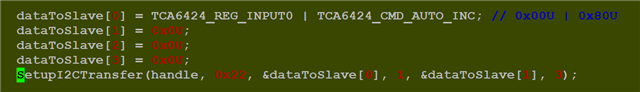
dataToSlave[0] = TCA6424_REG_INPUT0 | TCA6424_CMD_AUTO_INC; // 0x00U | 0x80U
dataToSlave[1] = 0x0U;
dataToSlave[2] = 0x0U;
dataToSlave[3] = 0x0U;
SetupI2CTransfer(handle, 0x22, &dataToSlave[0], 1, &dataToSlave[1], 3);
/* Set P06 and P07 to 1.
P06: MCAN0_EN, MCAN0 PHY Enable, Active High ('0' - device disabled, '1' normal operation)
P07: MCAN0_STB#, MCAN0 PHY Standby, Active Low ('0' - device standby, '1' - normal operation)
* Set P13 and P14 to 0.
P13: MLB_MUX_SEL, Signal Mux Control ('0' - MCAN2/Expansion, '1' - 3 Wire MLB)
P14: MCAN_MUX_SEL, Signal Mux Control ('0' - MCAN2/GPIO, '1' - Expansion/EQEP)
*/
dataToSlave[0] = TCA6424_REG_OUTPUT0 | TCA6424_CMD_AUTO_INC; // 0x04U | 0x80U
dataToSlave[1] |= 0xC0;
dataToSlave[2] &= ~(0x18);
SetupI2CTransfer(handle, 0x22, &dataToSlave[0], 1, &dataToSlave[1], 3);
}