This thread has been locked.

If you have a related question, please click the "Ask a related question" button in the top right corner. The newly created question will be automatically linked to this question.

TDA4VM: Please help me to write relation register parameters' value,and the source code about initialize MCAN and sending message.

Part Number: TDA4VM

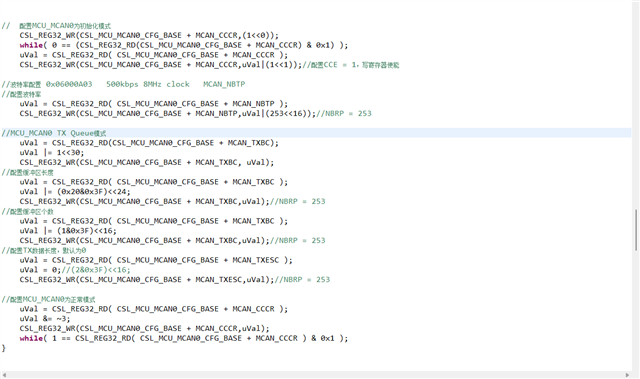
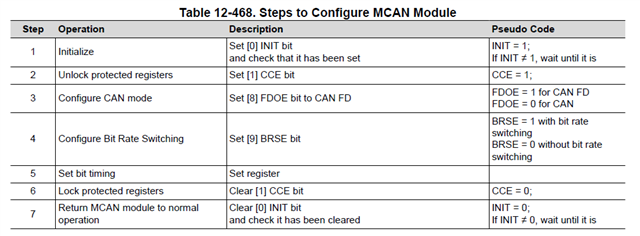
I know the initialization process shown in the figure, and I am not sure about the other register parameters except for the CCE and INIT registers

I have also seen examples :D:\ti-processor-sdk-rtos-j721e-evm-08_04_00_06\mcusw\mcal_drv\mcal,

I can see the logic and process, but I cannot see the parameters in the registers and the operations on the registers when sending information, which makes me confused when developing drivers.

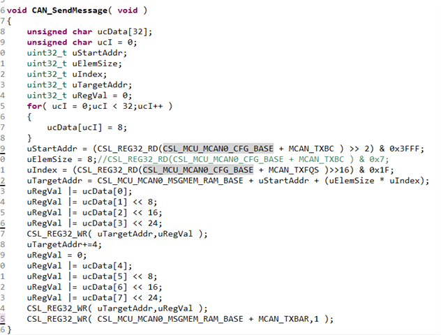
Please provide me with a function to initialize the MCU_MCAN0 register (including register parameters) and a function to send information (including register parameters). I would greatly appreciate it

Also uncertain about the write address of the message to be sent,

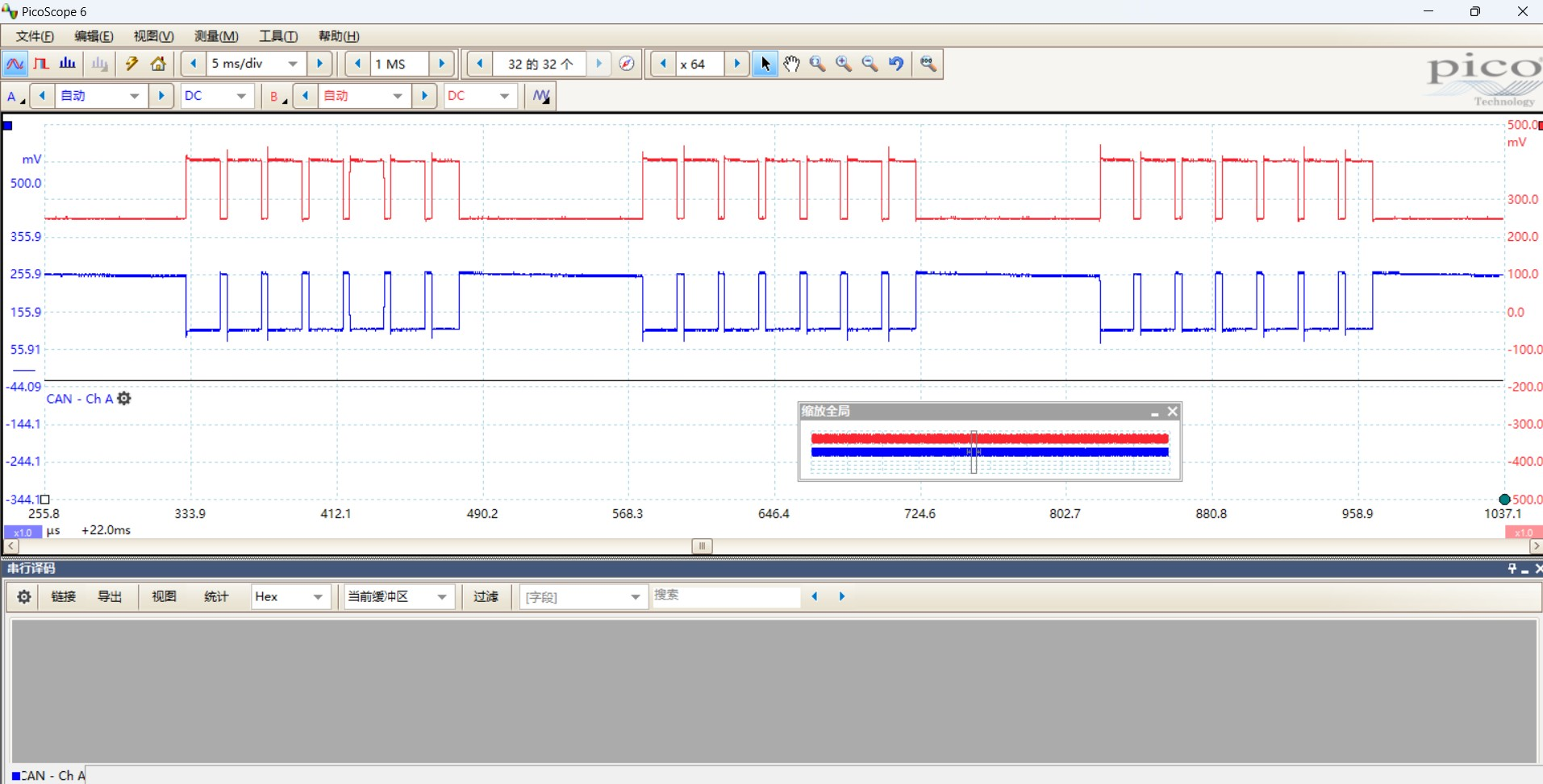
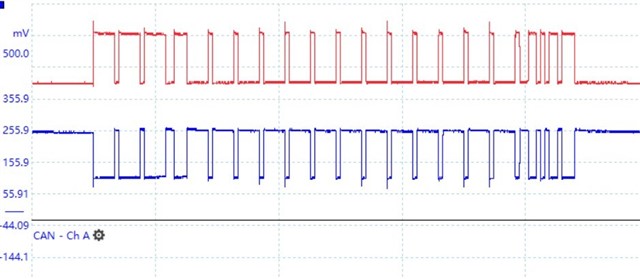
I filled in the register values myself according to my understanding of the manual as shown below, it must be incorrect because I didn't see any waveform changes on J1 MCU_CAN0.

  • To initialize the MCU_MCAN0 register, you would typically set the various configuration parameters such as the bit timing, message filters, and interrupt settings. For sending information, you would need to set up the message object with the appropriate data and then trigger the transmission.

  • Yes,I know the procedure must be like that you said.I have found a demo on DSP280039 about Initialize MCAN registers,Iearned it and program a myself code below.

    Fullscreen
    1
    2
    3
    4
    5
    6
    7
    8
    9
    10
    11
    12
    13
    14
    15
    16
    17
    18
    19
    20
    21
    /*
    * mcan.c
    *
    * Created on: 20231130
    * Author: 18780
    */
    #include "cslr_soc_baseaddress.h"
    #include "cslr_mcu_ctrl_mmr.h"
    #include "cslr_main_ctrl_mmr.h"
    #include "cslr_wkup_ctrl_mmr.h"
    #include "Stdint.h"
    #include "hw_mcanss.h"
    #include "mcan.h"
    #include "common.h"
    MCAN_INIT gsMcanInitParams;
    MCAN_TxBufElement gsMCAN_TxBuf;
    //
    XXXXXXXXXXXXXXXXXXXXXXXXXXXXXXXXXXXXXXXXXXXXXXXXXX

    However,I'v got the CAN message like this:

    Baudrate is  not 500Kbps,there is no DATA field,control field has no ID erther.I have tried my best to read the register manual :J721E_registers5.pdf  section 4.2 MCAN,I've no idear.

    if I set: 

    #define MCAN_RX_BUFF_NUM                (0U)//without receive function

    I can get a correct struct of CAN message with wrong baudrate  and wrong ID ,as is shown below:

    By the way, for the same BitTimingParams, the debugging results last night and this morning were different. Last night, it was still 2us  each bit, and this morning it was 5.4us each bit.

    I really don't know how to solve this problem. I don't know how to solve it

  • Regarding the differences in debugging results, it's possible that there may be some environmental or configuration changes causing the variation in timing.

    Additionally, double-check the BitTimingParams and ensure that they are set consistently.

    Look forward to your feedback

x 出现错误。请重试或与管理员联系。