PGA460: Echo measurement data issues

Part Number: PGA460


I used command 05 to read measurement results, monitoring only one object, but the return value shows the first four bytes of command 07. What's going on? Both setting 0 and setting 1 for DATADUMP_EN return the first four bytes of command 07. Below is an example of the return value when setting 1:image.png

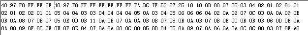
The first part shows the response to command 05, followed by the response to command 07, both using a 300 kHz frequency.

  • Hello, we have received your case. The investigation will take some time. Thank you for your patience.

  • Additionally, when I send commands, modifying the checksum of the same command still returns data. For example, sending 0x55 0x05 0xFA and 0x55 0x05 0x00 both receive responses. This also applies to the first four bytes of command 07. When DATADUMP_EN is set to 0, using command 07 continuously returns the same bytes.

  • Hi,

    Thank you for posting to the Sensors forum!

    Do you know what the customer's register configurations are? Also are they using their own custom PCB or the BOOSTXL-PGA460 EVM?

  • Lydia, hello. I'm using a custom-made PCB, the schematic for which is here:


    Some of these registers are configured as follows:

     threshold:

    P1_THR_00x88

    P1_THR_10x88

    P1_THR_20x88

    P1_THR_30x88

    P1_THR_40x88

    P1_THR_50x88

    P1_THR_60x84

    P1_THR_70x21

    P1_THR_80x08

    P1_THR_90x42

    P1_THR_100x10

    P1_THR_110x80

    P1_THR_120x80

    P1_THR_130x80

    P1_THR_140x80

    P1_THR_150x00

    P2_THR_00x88

    P2_THR_10x88

    P2_THR_20x88

    P2_THR_30x88

    P2_THR_40x88

    P2_THR_50x88

    P2_THR_60x84

    P2_THR_70x21

    P2_THR_80x08

    P2_THR_90x42

    P2_THR_100x10

    P2_THR_110x80

    P2_THR_120x80

    P2_THR_130x80

    P2_THR_140x80

    P2_THR_150x00


     TVG:

    TCGAIN0  0x44

    TCGAIN1  0x44

    TCGAIN2  0x44

    TCGAIN3  0x0C

    TCGAIN4  0x64

    TCGAIN5  0x9A

    TCGAIN6  0x99

    INIT_GAIN  0x00


    PULSE:

    FREQUENCY,0x0F

    PULSE_P1, 0x14

    PULSE_P2, 0x14

    REC_LENGTH,0x11

  • 您好,

    感谢您提供更多信息!

    我只是需要一些时间来看看这个,并将在明天结束时回复你。

  • Hi,

    Would it be possible to send me an oscilloscope capture of their communication when they send the command 5?

  • Sure thing. I'll show you the screenshots captured by the oscilloscope during their communication right away. This is the oscilloscope capture when sending command 5. Below is another screenshot of the oscilloscope capture when sending command 7. Hope this helps.

  • Hi,

    Looking at the waveform for the command 5 capture, the signal doesn't look quite right. The pulse circled below seems too long.

    The image below is from a working command 5 signal, and as you can see does not look the same as the signal captured by the customer.

    Regards,

    Lydia

  • I sincerely apologize for my mistake in sending you the oscilloscope screenshot for Command 1 instead of Command 5. Below is the correct screenshot for Command 5.

    As you can see, my Command 5 is identical to other clients' Command 5. I received a response, but it contained only the first few bytes of Command 7.

  • Hi,

    When using command 5, the echo data dump bit (DATADUMP_EN) must be disabled, otherwise the read out data will be invalid/out-of-date. From the initial post, it looks like only the data from when the echo data dump bit was enabled was shared. Would you be able to share what the data you are observing when DATADUMP_EN = 0 for command 5?

    That data that you should be reading back from the PGA460 following command 5 is the following: xdiag , 0xtime_of_flight_in_us_[MSB],  0xtime_of_flight_in_us_[LSB], 0xtime_object_width_in_us, 0xpeak_amplidute_in_LSB, 0xchecksum

  • Sure. When I disable the echo data dump bit (DATADUMP_EN), the return value of command 5 is still the first four bytes of command 7's return value. I'll provide these data points separately below:

    The above shows the returns for command 5 and command 7 when register 4B (TEST_MUX) = 0x22 and 40 (EE_CNTRL) = 0x80 (DATADUMP_EN = 1).

    The above results apply when register 4B (TEST_MUX) = 0x23 and 40 (EE_CNTRL) = 0x80 (DATADUMP_EN = 1); the returns for commands 5 and 7 are the same as above.

    When register 4B (TEST_MUX) = 0x22 and 40 (EE_CNTRL) = 0x00 (DATADUMP_EN = 0), both command 5 and command 7 return twice. Command 7's return value remains unchanged.

    My command 5 return value is consistently the first four bytes of command 7's return value across all scenarios. The probe frequency I used is 200KHz.

  • Hi ,

    Prior to command 5, what command is being sent? I just wanted to check to make sure that the customer is executing the following commands to read back the ultrasonic measurement results properly:

    1. Send a burst/listen command (command 0-3) while DATADUMP_EN=0 (start-up default)
    2. Wait for the burst/listen command to finish execution based on the present record length time (between 5-66ms). I recommend you wait 100ms for debug.
    3. Then send the ultrasonic measurement results command (command 5)
  • Hi,

    Before Command 5 are burst and listen commands (0x55, 0x01, 0x01, 0xFD), followed by a delay command, then Command 5. The procedure is as follows:

    1. Configure all registers (including setting DATADUMP_EN=0), then send the preset burst/listen command (Command 0x01)

    2. Regardless of distance, I directly set a 100ms delay

    3. Send the ultrasonic measurement result command (Command 5, 0x55, 0x05, 0xFA)

    These are my operational steps.

    Beyond the above issue, I also have additional questions:

    1. Is there a recommended register configuration for 200KHz operation?

    2. Could this issue stem from my hardware circuitry?

    3. Can I directly access the internal registers within the PGA460 that store this measurement data? (If so, how should I proceed? What are the addresses?)

  • Hi,

    How many objects is the customer trying to detect? Also, what is the range that the customer is trying to detect? What could be happening is that by the time the record interval is completed, the object(s) locations remain undetected and are assigned a value of 0xFF. See thread linked below for recommended settings for 200kHz to see if the suggestions in the thread help.

    Also, something to keep in mind is that command 5 and command 7 cannot be run back-to-back as command 7 requires DATADUMP_EN to be set to 1 and command 5 requires DATADUMP_EN to be set to 0 or the data read back will be invalid.

    1. Is there a recommended register configuration for 200KHz operation?

    Yes, the thread linked below details the recommended register configuration for 200kHz using command 5:

      PGA460: Unable to read echo detection results at 200KHz burst frequency 

    2. Could this issue stem from my hardware circuitry?

    I think it's more likely to be a configuration issue than something related to your circuitry, especially as you are able to communicate to the device.

    3. Can I directly access the internal registers within the PGA460 that store this measurement data? (If so, how should I proceed? What are the addresses?)

    No.

  • HI,

    Currently, only one object needs to be detected, with the detection range currently within 1 meter. I've reviewed this post and used Command 7 to obtain the echo data. I also plotted the image using Python and can see one object, but there are many similar waveforms in the background, as shown in the image below.I used the configuration for the registers in this post, then modified some parts according to my own needs.

    The first waveform in this image shows the position of my object, and the distance is roughly the same. However, when I use command 5, it still returns the first four bytes from command 7 instead of the normal flight time data. Why is that?

  • Hi,

    I think that the scaling may be a bit off, it's hard to fully see all of the waveforms in the image shared. Could you share the plot again a bit zoomed out?

    Just as a sanity check, could you try using command 5 with a different PGA460 device to see if you get the same results (the will help determine if the issue that you are having is device or system specific)?

  • Hi,

    Sorry for wasting your time with this question. I'll adjust the screen right away.

    This is the complete waveform from my retest. At the red arrow location, an object is indeed visible in the echo data. However, once echo data storage is disabled, Command 5 still fails to detect any data. Furthermore, the issue I initially mentioned pertains to the first four bytes of Command 7.

    At the same time, I noticed another issue:

    1. When using commands 5 and 7, the device always returns information regardless of the final checksum value. However, when sending command 1, the checksum must be correct for the transmission to occur.

    2. When echo data storage is disabled (DATADUMP_EN=0), resending command 7 reveals the previously configured threshold register value in the return data.

    I'm unsure whether these are normal behaviors or related to my issue.