Other Parts Discussed in Thread: DCA1000EVM, AWR2243, AWR1243
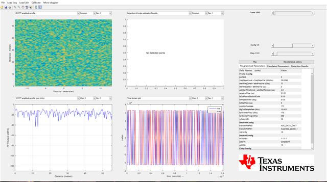
用mmwavelink_example来配置雷达,采集雷达数据,得到的数据大小不对。
相同的配置下比用mmWave studio采集的数据量少一半。
我使用3发4收的雷达,采样点数为173,chirpLoops数为101,帧数为960,数据格式采用complex 1x(16bits)
理论上采集的数据大小应该是:3*4*173*101*960*4 bytes = 805 155 840 bytes
但是实际只采集到402 577 920 bytes的数据,更好是理论的一半。
请问能帮忙看一下,我配置中哪里出了问题?以下是mmwaveconfig.txt和DCA1000EVM_CLI的一些关键配置。
#3t4r

#For detailed view of mmWave Radar configuration structure
#please refer
#ti\control\mmwavelink\docs\doxygen\html\index.html
#

#
#Global configuration
#Advanced frame test enable/disable; 1 - Advanced frame; 0 - Legacy frame
#Continuous mode test enable/disable; 1 - Enable; 0 - Disable
#Dynamic chirp test enable/disable; 1 - Enable; 0 - Disable; This should not be enabled if Advanced chirp test is enabled
#Dynamic profile test enable/disable; 1 - Enable; 0 - Disable
#Advanced chirp test enable/disable; 1 - Enable; 0 - Disable; The legacy chirp API is not required if this is enabled
#Firmware download enable/disable; 1 - Enable; 0 - Disable
#mmWaveLink logging enable/disable; 1 - Enable; 0 - Disable
#Calibration enable/disable; To perform calibration store/restore; 1 - Enable; 0 - Disable
#Calibration Store/Restore; If CalibEnable = 1, then whether to store/restore; 1 - Store; 0 - Restore
#Transport mode; 1 - I2C; 0 - SPI
#Flash connected enable/disable; 1 - Enable; 0 - Disable
#
# 是否启用高级帧
LinkAdvanceFrameTest=0;
LinkContModeTest=0;
LinkDynProfileTest=0;
LinkDynChirpTest=0;
LinkAdvChirpTest=0;
EnableFwDownload=1;
# 日志
EnableMmwlLogging=1;
# 是否校准
CalibEnable=0;
CalibStoreRestore=1;
# 传输模式 SPI
TransferMode=0;
IsFlashConnected=1;
#END

#
#power on master arguments, please modify if needed.
#rlClientCbs_t: crcType 0:16Bit/1:32Bit/2:64Bit, ackTimeout
#
crcType=1;
ackTimeout=1000;
#END

#
#channel config parameters, please modify if needed.
#rlChanCfg_t 通道配置
channelTx=7;
channelRx=15;
# 级联模式
cascading=0;
#END

#
#ADC out config parameters, please modify if needed.
#rlAdcOutCfg_t
#0-12bits; 1-14bits; 2-16bits
adcBits=2;
# 0-real; 1-Complex 1x;2-Complex 2x
adcFormat=1;
#END

#
#DATA format config parameters, please modify if needed.
#rlDevDataFmtCfg_t
#0b1111-四收
rxChanEn=15;
# 0-12bits;1-14bits;2-16bits
adcBitsD=2;
# 0-real;1-Complex 1x;2-Complex 2x
adcFmt=1;
# 0-I first;1-Q first
iqSwapSel=0;
# 0交错模式
chInterleave=0;
#END

#
#Low power config Paramters, please modify if needed.
#rlLowPowerModeCfg_t 未知 ############
#
anaCfg=0;
lpAdcMode=0;
#END

#
#Data Path config parameters, please modify if needed
# 0-CSI2; 1-LVDS
intfSel=1;
transferFmtPkt0=1;
transferFmtPkt1=0;
cqConfig=2;
cq0TransSize=64;
cq1TransSize=64;
cq2TransSize=64;
#END

#
#LVDS clock config parameters, please modify if needed
#rlDevDataPathClkCfg_t
# 时钟类型 0 SDR; 1 DDR
laneClk=1;
dataRate=1;
#END

#
#SET HSI clock parameters, please modify if needed.
#rlDevHsiClk_t 未知 ############
#
hsiClk=9
#END

#
#LANE config parameters, please modify if needed.
#rlDevLaneEnable_t
# 0b1111 四个通道
#
laneEn=15;
#END

#
#LVDS Lane Config parameters, please modify if needed.
#rlDevLvdsLaneCfg_t  未知 ############
#
laneFmtMap=0;
laneParamCfg=1;
#END

#
#Programmable Filter config parameters, please modify if needed.
#rlRfProgFiltConf_t 未知作用######
#
profileId=0;
coeffStartIdx=0;
progFiltLen=14;
progFiltFreqShift=100;
#END

#
#Profile config parameters, please modify if needed.
#rlProfileCfg_t
#
profileId=0;
pfVcoSelect=2;
startFreqConst=1435384036;
idleTimeConst=300;
adcStartTimeConst=420;
rampEndTime=2122;
txOutPowerBackoffCode=0;
txPhaseShifter=0;
freqSlopeConst=593;
txStartTime=100;
numAdcSamples=173;
digOutSampleRate=10604;
hpfCornerFreq1=0;
hpfCornerFreq2=0;
rxGain=30;
#END


#
#Chirp Configuration parameters, please modify if needed.
#rlChirpCfg_t
#
chirpStartIdx=0;
chirpEndIdx=0;
profileIdCPCFG=0;
startFreqVar=0;
freqSlopeVar=0;
idleTimeVar=0;
adcStartTimeVar=0;
# 0b0001
txEnable=1;
#END

#
#Chirp Configuration parameters, please modify if needed.
#rlChirpCfg_t
#
chirpStartIdx=1;
chirpEndIdx=1;
profileIdCPCFG=0;
startFreqVar=0;
freqSlopeVar=0;
idleTimeVar=0;
adcStartTimeVar=0;
# 0b0100
txEnable=4;
#END

#
#Chirp Configuration parameters, please modify if needed.
#rlChirpCfg_t
#
chirpStartIdx=2;
chirpEndIdx=2;
profileIdCPCFG=0;
startFreqVar=0;
freqSlopeVar=0;
idleTimeVar=0;
adcStartTimeVar=0;
# 0b0010
txEnable=2;
#END

#
#Frame configuration parameters, please modify if needed.
#rlFrameCfg_t
#
chirpStartIdxFCF=0;
chirpEndIdxFCF=2;
frameCount=960;
loopCount=101;
periodicity=12500000;
triggerDelay=0;
numAdcSamples=173;
# 软件触发
triggerSelect=1;
#END
{
	"DCA1000Config": {
		"dataLoggingMode": "multi",
		"dataTransferMode": "LVDSCapture",
		"dataCaptureMode": "ethernetStream",
		"lvdsMode": 1,
		"dataFormatMode": 3,
		"packetDelay_us": 25,
		"ethernetConfig": {
			"DCA1000IPAddress": "192.168.33.180",
			"DCA1000ConfigPort": 4096,
			"DCA1000DataPort": 4098
		},
		"ethernetConfigUpdate": {
			"systemIPAddress": "192.168.33.30",
			"DCA1000IPAddress": "192.168.33.181",
			"DCA1000MACAddress": "12.34.56.78.90.12",
			"DCA1000ConfigPort": 4096,
			"DCA1000DataPort": 4098,
		},
		"captureConfig": {
			"fileBasePath": "D:\\RadarData\\cmd",
			"filePrefix": "adc_data",
			"maxRecFileSize_MB": 1024,
			"sequenceNumberEnable": 1,
			"captureStopMode": "frames",
			"framesToCapture": 960
		},
		"dataFormatConfig": {
			"MSBToggle": 1,
			"reorderEnable": 1,
			"laneFmtMap": 3,
			"dataPortConfig": [
				{
					"portIdx": 0,
					"dataType": "complex"
				},
				{
					"portIdx": 1,
					"dataType": "complex"
				},
				{
					"portIdx": 2,
					"dataType": "complex"
				},
				{
					"portIdx": 3,
					"dataType": "complex"
				},
				{
					"portIdx": 4,
					"dataType": "complex"
				}
			]
		}
	}
}