This thread has been locked.
If you have a related question, please click the "Ask a related question" button in the top right corner. The newly created question will be automatically linked to this question.
我使用AWR2243BOOST+DCA1000采集radar数据, 在一个空旷场地测一个角反射器。
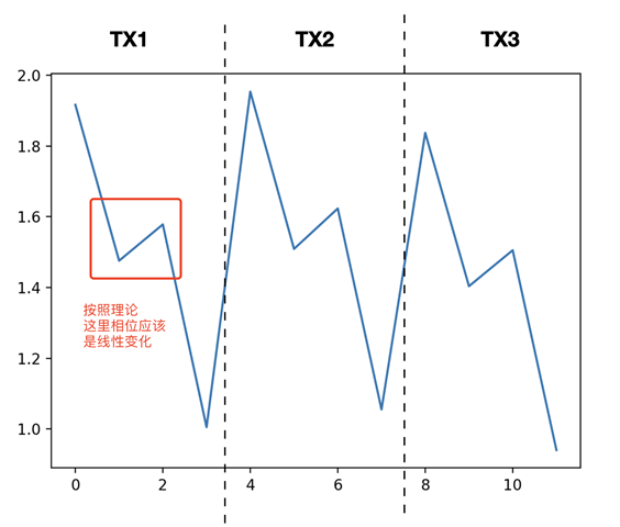
使用我自己的脚本读取bin文件,并进行rangefft和doppler fft后, range-doppler情况符合预期。 但是当我提取出在角反射器位置的数据的相位情况,如下图所示,发现RX2相比RX0 RX1 RX3相位会有个固定的偏移,不符合“相位周期性变化”的预期。 虽然对着当前信号做anglefft也能得到大致正确的角度位置, 这个偏移可能会影响最终求角度的精度
下图纵坐标是相位, 横坐标是0-12,分别是使用MIMO-TDM后 [ TX0-RX0 , TX0-RX1 , TX0-RX2 , TX0-RX3 , TX1-RX0 , TX1-RX1 , TX1-RX2 , TX1-RX3 , TX2-RX0 , TX2-RX1 , TX2-RX2 , TX2-RX3 ]
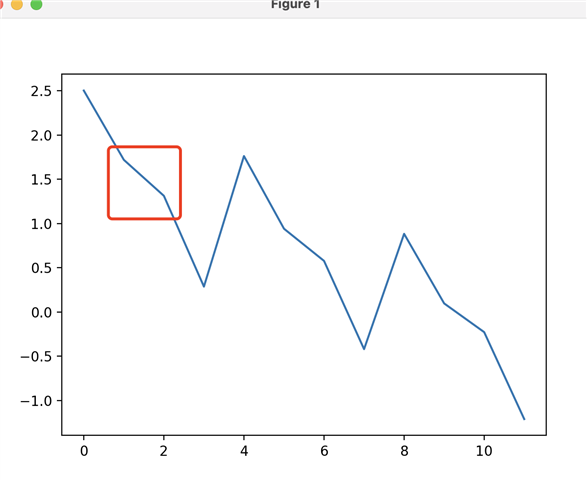
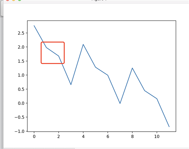
我再测了另外几组也是类似的规律。
经过搜索后我查到有个东西叫RX calibration。 但我没查到如何在mmwave studio上做这件事。
您好,
能否请您提供以下信息:
1. 请问在您给出的图中,y 轴是以什么单位(度数或弧度)表示的?
2. Rx gain calibration并无法帮助解决上面的相位问题。
3. 该问题也有可能是由于天线电平不匹配造成的。 您能否提供有关天线放置和对齐的更多信息?
您好,非常感谢您的回复。
1. 我的y轴是弧度表示。
2. 请问为啥“Rx gain calibration并无法帮助解决上面的相位问题”。
3. 我就是使用awr2243boost single chip。 天线排列应该是固定的。 同时我也没做啥特殊处理,就是简单修改了一下mmstudio中给的 DataCaptureDemo_xWR.lua,并改成支持MIMO的模式。
-- All the parameters used in this script are default parameters used in the mmWaveStudio GUI. -- It captures the ADC data using DCA1000. -- The user is expected to change the configuration according to specific use-cases. -- Change "operating_mode" in line 15 based on the usecase --BSS and MSS firmware download info = debug.getinfo(1,'S'); file_path = (info.source); file_path = string.gsub(file_path, "@",""); file_path = string.gsub(file_path, "DataCaptureDemo_xWR_TDM.lua",""); fw_path = file_path.."..\\..\\rf_eval_firmware" --Mode of operation. --Legacy Framing mode = 0/Advanced framing mode = 1/Continous streaming mode = 2 operating_mode = 0 --Export bit operation file bitopfile = file_path.."\\".."bitoperations.lua" dofile(bitopfile) --Read part ID --This register address used to find part number res, efusedevice = ar1.ReadRegister(0xFFFFE214, 0, 31) efuseES2ES3Device = bit_and(efusedevice, 0x03FC0000) efuseES2ES3Device = bit_rshift(efuseES2ES3Device, 18) if(efuseES2ES3Device == 0x30 or efuseES2ES3Device == 0x6) then partId = 2243E0 elseif(efuseES2ES3Device == 0x31 or efuseES2ES3Device == 0x32) then partId = 2243E1 else WriteToLog("Invalid Device part number\n" ..partId) end --ES version res, ESVersion = ar1.ReadRegister(0xFFFFE218, 0, 31) ESVersion = bit_and(ESVersion, 15) --ADC_Data file path data_path = file_path.."..\\PostProc" adc_data_path = data_path.."\\adc_data.bin" -- Download Firmware if(partId == 2243E0) then BSS_FW = fw_path.."\\AWR2243_ES1_0\\radarss\\xwr22xx_radarss.bin" MSS_FW = fw_path.."\\AWR2243_ES1_0\\masterss\\xwr22xx_masterss.bin" elseif(partId == 2243E1) then BSS_FW = fw_path.."\\AWR2243_ES1_1\\radarss\\xwr22xx_radarss.bin" MSS_FW = fw_path.."\\AWR2243_ES1_1\\masterss\\xwr22xx_masterss.bin" else WriteToLog("Invalid Device partId FW\n" ..partId) WriteToLog("Invalid Device ESVersion\n" ..ESVersion) end -- Download BSS Firmware if (ar1.DownloadBSSFw(BSS_FW) == 0) then WriteToLog("BSS FW Download Success\n", "green") else WriteToLog("BSS FW Download failure\n", "red") end RSTD.Sleep(100) -- Download MSS Firmware if (ar1.DownloadMSSFw(MSS_FW) == 0) then WriteToLog("MSS FW Download Success\n", "green") else WriteToLog("MSS FW Download failure\n", "red") end RSTD.Sleep(100) -- SPI Connect if (ar1.PowerOn(1, 1000, 0, 0) == 0) then WriteToLog("Power On Success\n", "green") else WriteToLog("Power On failure\n", "red") end RSTD.Sleep(100) -- RF Power UP if (ar1.RfEnable() == 0) then WriteToLog("RF Enable Success\n", "green") else WriteToLog("RF Enable failure\n", "red") end RSTD.Sleep(100) if (ar1.ChanNAdcConfig(1, 1, 1, 1, 1, 1, 1, 2, 1, 0) == 0) then WriteToLog("ChanNAdcConfig Success\n", "green") else WriteToLog("ChanNAdcConfig failure\n", "red") end RSTD.Sleep(100) if (ar1.LPModConfig(0, 0) == 0) then WriteToLog("Regualar mode Cfg Success\n", "green") else WriteToLog("Regualar mode Cfg failure\n", "red") end RSTD.Sleep(100) if (ar1.RfInit() == 0) then WriteToLog("RfInit Success\n", "green") else WriteToLog("RfInit failure\n", "red") end RSTD.Sleep(1000) if (ar1.DataPathConfig(1, 1, 0) == 0) then WriteToLog("DataPathConfig Success\n", "green") else WriteToLog("DataPathConfig failure\n", "red") end RSTD.Sleep(100) if (ar1.LvdsClkConfig(1, 1) == 0) then WriteToLog("LvdsClkConfig Success\n", "green") else WriteToLog("LvdsClkConfig failure\n", "red") end RSTD.Sleep(100) if (ar1.LVDSLaneConfig(0, 1, 1, 1, 1, 1, 0, 0) == 0) then WriteToLog("LVDSLaneConfig Success\n", "green") else WriteToLog("LVDSLaneConfig failure\n", "red") end RSTD.Sleep(100) if((operating_mode == 0) or (operating_mode == 1)) then if(ar1.ProfileConfig(0, 77, 6, 6, 32, 0, 0, 0, 0, 0, 0, 29.982, 0, 256, 10000, 0, 0, 94) == 0) then WriteToLog("ProfileConfig Success\n", "green") else WriteToLog("ProfileConfig failure\n", "red") end RSTD.Sleep(100) if (ar1.ChirpConfig(0, 0, 0, 0, 0, 0, 0, 1, 0, 0)== 0) then WriteToLog("ChirpConfig Success\n", "green") else WriteToLog("ChirpConfig failure\n", "red") end if (ar1.ChirpConfig(1, 1, 0, 0, 0, 0, 0, 0, 1, 0) == 0) then WriteToLog("ChirpConfig Success\n", "green") else WriteToLog("ChirpConfig failure\n", "red") end if (ar1.ChirpConfig(2, 2, 0, 0, 0, 0, 0, 0, 0, 1) == 0) then WriteToLog("ChirpConfig Success\n", "green") else WriteToLog("ChirpConfig failure\n", "red") end end RSTD.Sleep(100) if(operating_mode == 0) then if (ar1.FrameConfig(0, 2, 1, 128, 30, 0, 1) == 0) then WriteToLog("FrameConfig Success\n", "green") else WriteToLog("FrameConfig failure\n", "red") end elseif(operating_mode == 1) then if (ar1.AdvanceFrameConfig(4, 1536, 0, 0, 1, 128, 8000000, 0, 1, 1, 8000000, 0, 0, 1, 128, 8000000, 0,1, 1, 8000000, 0, 0, 1, 128, 8000000, 0, 1, 1, 8000000, 0, 0, 1, 128,8000000, 0, 1, 1, 8000000, 8, 1, 0, 1, 128, 0, 1, 128, 1, 1, 128,1, 1, 128, 1, 1) == 0) then WriteToLog("AdvanceFrameConfig Success\n", "green") else WriteToLog("AdvanceFrameConfig failure\n", "red") end end RSTD.Sleep(100) -- select Device type if (ar1.SelectCaptureDevice("DCA1000") == 0) then WriteToLog("SelectCaptureDevice Success\n", "green") else WriteToLog("SelectCaptureDevice failure\n", "red") end --DATA CAPTURE CARD API if (ar1.CaptureCardConfig_EthInit("192.168.33.30", "192.168.33.180", "12:34:56:78:90:12", 4096, 4098) == 0) then WriteToLog("CaptureCardConfig_EthInit Success\n", "green") else WriteToLog("CaptureCardConfig_EthInit failure\n", "red") end if (ar1.CaptureCardConfig_Mode(1, 1, 1, 2, 3, 30) == 0) then WriteToLog("CaptureCardConfig_Mode Success\n", "green") else WriteToLog("CaptureCardConfig_Mode failure\n", "red") end if (ar1.CaptureCardConfig_PacketDelay(25) == 0) then WriteToLog("CaptureCardConfig_PacketDelay Success\n", "green") else WriteToLog("CaptureCardConfig_PacketDelay failure\n", "red") end if((operating_mode == 0) or (operating_mode == 1)) then --Start Record ADC data ar1.CaptureCardConfig_StartRecord(adc_data_path, 1) RSTD.Sleep(2000) --Trigger frame ar1.StartFrame() RSTD.Sleep(10000) --Post process the Capture RAW ADC data ar1.StartMatlabPostProc(adc_data_path) WriteToLog("Please wait for a few seconds for matlab post processing .....!!!! \n", "green") RSTD.Sleep(10000) else --Continuous streaming if(ar1.ContStrConfig(77, 9000, 94, 0, 0, 0, 0, 0, 0, 0, 0) == 0) then WriteToLog("ContStrConfig Success\n", "green") else WriteToLog("ContStrConfig failure\n", "red") end -- Start Continuous streaming of AWR device ar1.ContStrModEnable() -- Number of samples to capture ar1.BasicConfigurationForAnalysis(16384, 16384, 1, 0, 0, 0, 1) --Start Record continuous data ar1.CaptureCardConfig_StartRecord_ContinuousStreamData(adc_data_path, 0) RSTD.Sleep(5000) -- Stop Continuous streaming of AWR device ar1.ContStrModDisable() --Post process the Capture data ar1.ProcessContStreamADCData(adc_data_path) WriteToLog("Please wait for a few seconds for matlab post processing .....!!!! \n", "green") RSTD.Sleep(10000) end
抱歉回复晚了。
2. 请问为啥“Rx gain calibration并无法帮助解决上面的相位问题”。
RX 增益校准会根据 RX 增益测量的结果、温度和系统配置的 RX 增益来设置应用最佳的 RX LNA 设置和 RX IFA 设置,而且在所有4个 RX 中都是相同的。 因此并不能帮助减轻 RX 之间的相位差。
3. 我就是使用awr2243boost single chip。 天线排列应该是固定的。 同时我也没做啥特殊处理,就是简单修改了一下mmstudio中给的 DataCaptureDemo_xWR.lua,并改成支持MIMO的模式。
您可以考虑在角度= 0时使用角反射器测量 RX0、1、2、3的相位。 这样就可以找到每个 RX 的偏移量,然后在实际现场测量时校准偏移量。