Part Number: TPS53681
尊敬的技术工作者:
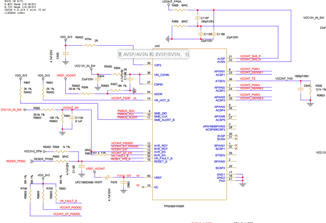
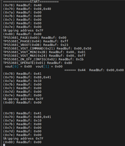
附件是我的驱动文件及驱动log。我目前只使用了A通道的三相,我阅读芯片手册,需要先选择page,然后设置VOUT_COMMAND, 使能OPERATION,之后还有别的操作吗,并没有电压输出, 其他的寄存器在芯片手册中都有默认值,如 VOUT_MODE 只读 且设置为5mv,ON_OFF_CONFIG 默认设备1B,PHASE默认为FF,我不知道还需要设置那些寄存器,
#include <stdio.h>
#include <stdint.h>
#include <string.h>
#include "bsp_tps53681.h"
#include "gd32f10x_gpio.h"
extern uint8_t read_reg_data(uint8_t addr, uint8_t reg, uint8_t len, uint8_t *buf);
extern uint8_t write_reg_data(uint8_t addr, uint8_t reg, uint8_t len, uint8_t *buf);
typedef struct
{
uint8_t addr;
const char *name;
} reg_desc_t;
static const reg_desc_t status_regs[] = {
{0x78, "REG_STATUS_BYTE"},
{0x79, "REG_STATUS_WORD"},
{0x7A, "REG_STATUS_VOUT"},
{0x7B, "REG_STATUS_IOUT"},
{0x7C, "REG_STATUS_INPUT"},
{0x7D, "REG_STATUS_TEMP"},
{0x7E, "REG_STATUS_CML"},
{0x80, "REG_STATUS_MFR_SPECIFIC"}};
static const size_t status_regs_count = sizeof(status_regs) / sizeof(*status_regs);
int read_from_reg(uint8_t reg, uint8_t *buff, uint8_t len)
{
return read_reg_data(96, reg, len, buff);
}
int write_to_reg(uint8_t reg, uint8_t *buff, uint8_t len)
{
return write_reg_data(96, reg, len, buff);
}
// void dump_all_regs(uint8_t slave_addr)
// {
// for (size_t i = 0; i < status_regs_count; ++i)
// {
// uint8_t addr = status_regs[i].addr;
// uint8_t val = i2c_read(slave_addr, addr);
// printf("%s (0x%02X) = 0x%02X\n",
// status_regs[i].name, addr, val);
// }
// }
int parse_status_byte(uint8_t addr)
{
uint8_t status = 0;
read_from_reg(addr, &status, 1);
// Bit6: OFF (Power supply status)
if (status & (1 << 6))
{
printf("status_byte: not providing power to VOUT: %02x\n", status);
}
// Bit5: VOUT_OV (Output over-voltage fault)
if (status & (1 << 5))
{
printf("status_byte: Output over-voltage %02x\n", status);
}
// Bit4: IOUT_OC (Output over-current fault)
if (status & (1 << 4))
{
printf("status_byte: Output over-current %02x\n", status);
}
// Bit3: VIN_UV (Input under-voltage fault)
if (status & (1 << 3))
{
printf("status_byte: Input voltage below UVLO threshold (check input power supply)\n");
}
// Bit2: TEMP (Over-temperature fault/warning)
if (status & (1 << 2))
{
printf("status_byte: Over-temperature fault or warning (check thermal management)\n");
}
// Bit1: CML (Communication/memory/logic fault)
if (status & (1 << 1))
{
printf("status_byte:Communication/memory/logic anomaly (check PMBus connection or NVM)\n");
}
// Bit0: OTHER (Unclassified fault)
if (status & (1 << 0))
{
printf("status_byte: Unclassified fault (e.g., UVF, OCW; check other status registers)\n");
}
return 0xFF;
}
int parse_status_word(uint8_t addr)
{
uint8_t buffer[2] = {0}; // 用于存储原始字节
uint16_t status_word = 0;
int result;
// 读取两个字节数据
result = read_from_reg(addr, buffer, 2);
if (result != 0)
{
printf("ERROR: Failed to read STATUS_WORD (read %d bytes, expected 2)\n", result);
return -1;
}
// 正确处理Little Endian字节序:低字节在前,高字节在后
status_word = (uint16_t)buffer[1] << 8 | buffer[0];
printf("status_word: value: 0x%04X (Bytes: 0x%02X 0x%02X)\n", status_word, buffer[0], buffer[1]);
// Bit15: VOUT (Output voltage fault/warning)
if (status_word & (1 << 15))
{
printf("status_word: Output voltage bit warning\n");
}
// Bit14: IOUT (Output current fault/warning)
if (status_word & (1 << 14))
{
printf("status_word: Output current bit warning\n");
}
// Bit13: INPUT (Input voltage/current fault/warning)
if (status_word & (1 << 13))
{
printf("status_word: Input voltage bit warning\n");
}
// Bit12: MFR (Manufacturer-specific fault)
if (status_word & (1 << 12))
{
printf("status_word: MFR bit warning\n");
}
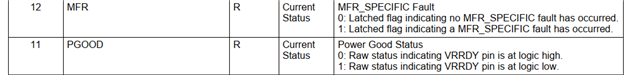
// Bit11: PGOOD (Power good status)
if (status_word & (1 << 11))
{
printf("status_word: Power NOT good (AVR_RDY/BVR_RDY pin is LOW)\n");
}
else
{
printf("status_word: Power good (AVR_RDY/BVR_RDY pin is HIGH)");
}
// Bit6: OFF (Power supply status)
if (status_word & (1 << 6))
{
printf("status_word: Not providing power to VOUT\n");
}
// Bit5: VOUT_OV (Output over-voltage fault)
if (status_word & (1 << 5))
{
printf("status_word: Output over-voltage fault detected\n");
}
// Bit4: IOUT_OC (Output over-current fault)
if (status_word & (1 << 4))
{
printf("status_word: Output over-current fault detected\n");
}
// Bit3: VIN_UV (Input under-voltage fault)
if (status_word & (1 << 3))
{
printf("status_word: Output Input-voltage fault detected\n");
}
// Bit2: TEMP (Over-temperature fault/warning)
if (status_word & (1 << 2))
{
printf("status_word: Over-temperature warning detected\n");
}
// Bit1: CML (Communication/memory/logic fault)
if (status_word & (1 << 1))
{
printf("status_word: Communication, memory, or logic fault detected\n");
}
// Bit0: OTHER (Unclassified fault)
if (status_word & (1 << 0))
{
printf("status_word: Unclassified fault detected\n");
}
return 0;
}
int parse_status_vout(uint8_t addr)
{
uint8_t status = 0; // Store 8-bit status value
read_from_reg(addr, &status, 1);
printf("\nRaw value: 0x%02X\n", status);
// Bit7: VOUT_OVF (Output Over-Voltage Fault)
if (status & (1 << 7))
{
printf("- Bit7 (VOUT_OVF): Output Over-Voltage Fault detected (latched). "
"Clear by writing 1 to this bit.\n");
}
else
{
printf("- Bit7 (VOUT_OVF): No output over-voltage fault detected.\n");
}
// Bit6: VOUT_OVW (Unsupported, always 0)
if ((status & (1 << 6)) != 0)
{
printf("- Bit6 (VOUT_OVW): Anomaly (this bit is unsupported and should be 0).\n");
}
// Bit5: VOUT_UVW (Unsupported, always 0)
if ((status & (1 << 5)) != 0)
{
printf("- Bit5 (VOUT_UVW): Anomaly (this bit is unsupported and should be 0).\n");
}
// Bit4: VOUT_UVF (Output Under-Voltage Fault)
if (status & (1 << 4))
{
printf("- Bit4 (VOUT_UVF): Output Under-Voltage Fault detected (latched). "
"Clear by writing 1 to this bit.\n");
}
else
{
printf("- Bit4 (VOUT_UVF): No output under-voltage fault detected.\n");
}
// Bit3: VOUT_MIN_MAX (Output Voltage Max/Min Exceeded Warning)
if (status & (1 << 3))
{
printf("- Bit3 (VOUT_MIN_MAX): Output voltage exceeded VOUT_MAX/VOUT_MIN limits. "
"Clear by writing 1 to this bit.\n");
}
else
{
printf("- Bit3 (VOUT_MIN_MAX): Output voltage within VOUT_MAX/VOUT_MIN limits.\n");
}
// Bit2: TON_MAX (Unsupported, always 0)
if ((status & (1 << 2)) != 0)
{
printf("- Bit2 (TON_MAX): Anomaly (this bit is unsupported and should be 0).\n");
}
// Bit1: TOFF_MAX (Unsupported, always 0)
if ((status & (1 << 1)) != 0)
{
printf("- Bit1 (TOFF_MAX): Anomaly (this bit is unsupported and should be 0).\n");
}
// Bit0: VOUT_TRACK (Unsupported, always 0)
if ((status & (1 << 0)) != 0)
{
printf("- Bit0 (VOUT_TRACK): Anomaly (this bit is unsupported and should be 0).\n");
}
return 0;
}
int parse_status_iout(uint8_t addr)
{
uint8_t status = 0; // Store 8-bit status value
read_from_reg(addr, &status, 1);
printf("\nRaw value: 0x%02X\n", status);
// Bit7: IOUT_OCF (Output Over-Current Fault)
if (status & (1 << 7))
{
printf("- Bit7 (IOUT_OCF): Output Over-Current Fault detected (latched). "
"Clear by writing 1 to this bit.\n");
}
else
{
printf("- Bit7 (IOUT_OCF): No output over-current fault detected.\n");
}
// Bit6: IOUT_OCUVF (Unsupported, always 0)
if ((status & (1 << 6)) != 0)
{
printf("- Bit6 (IOUT_OCUVF): Anomaly (this bit is unsupported and should be 0).\n");
}
// Bit5: IOUT_OCW (Output Over-Current Warning)
if (status & (1 << 5))
{
printf("- Bit5 (IOUT_OCW): Output Over-Current Warning detected (latched). "
"Clear by writing 1 to this bit.\n");
}
else
{
printf("- Bit5 (IOUT_OCW): No output over-current warning detected.\n");
}
// Bit4: IOUT_UCF (Unsupported, always 0)
if ((status & (1 << 4)) != 0)
{
printf("- Bit4 (IOUT_UCF): Anomaly (this bit is unsupported and should be 0).\n");
}
// Bit3: CUR_SHAREF (Current Sharing Fault)
if (status & (1 << 3))
{
printf("- Bit3 (CUR_SHAREF): Current Sharing Fault detected (latched). "
"Clear by writing 1 to this bit.\n");
}
else
{
printf("- Bit3 (CUR_SHAREF): No current sharing fault detected.\n");
}
// Bit2: POW_LIMIT (Unsupported, always 0)
if ((status & (1 << 2)) != 0)
{
printf("- Bit2 (POW_LIMIT): Anomaly (this bit is unsupported and should be 0).\n");
}
// Bit1: POUT_OPF (Unsupported, always 0)
if ((status & (1 << 1)) != 0)
{
printf("- Bit1 (POUT_OPF): Anomaly (this bit is unsupported and should be 0).\n");
}
// Bit0: POUT_OPW (Unsupported, always 0)
if ((status & (1 << 0)) != 0)
{
printf("- Bit0 (POUT_OPW): Anomaly (this bit is unsupported and should be 0).\n");
}
return 0;
}
int parse_status_input(uint8_t addr)
{
uint8_t status = 0;
read_from_reg(addr, &status, 1);
// Step 2: Parse status bits and log results
printf("\n===== STATUS_INPUT (0x7C) Parsing Results =====");
printf("\nRaw value: 0x%02X\n", status);
// Bit7: VIN_OVF (Input Over-Voltage Fault)
if (status & (1 << 7))
{
printf("- Bit7 (VIN_OVF): Input Over-Voltage Fault detected (latched). "
"Clear by writing 1 to this bit.\n");
}
else
{
printf("- Bit7 (VIN_OVF): No input over-voltage fault detected.\n");
}
// Bit6: VIN_OVW (Unsupported, always 0)
if ((status & (1 << 6)) != 0)
{
printf("- Bit6 (VIN_OVW): Anomaly (this bit is unsupported and should be 0).\n");
}
// Bit5: VIN_UVW (Unsupported, always 0)
if ((status & (1 << 5)) != 0)
{
printf("- Bit5 (VIN_UVW): Anomaly (this bit is unsupported and should be 0).\n");
}
// Bit4: VIN_UVF (Input Under-Voltage Fault)
if (status & (1 << 4))
{
printf("- Bit4 (VIN_UVF): Input Under-Voltage Fault detected (latched). "
"Clear by writing 1 to this bit.\n");
}
else
{
printf("- Bit4 (VIN_UVF): No input under-voltage fault detected.\n");
}
// Bit3: LOW_VIN (Input Voltage Insufficient)
if (status & (1 << 3))
{
printf("- Bit3 (LOW_VIN): Converter turned off due to insufficient input voltage (latched). "
"Clear by writing 1 to this bit.\n");
}
else
{
printf("- Bit3 (LOW_VIN): Input voltage sufficient (no shutdown due to LOW_VIN).\n");
}
// Bit2: IIN_OCF (Input Over-Current Fault)
if (status & (1 << 2))
{
printf("- Bit2 (IIN_OCF): Input Over-Current Fault detected (latched). "
"Clear by writing 1 to this bit.\n");
}
else
{
printf("- Bit2 (IIN_OCF): No input over-current fault detected.\n");
}
// Bit1: IIN_OCW (Input Over-Current Warning)
if (status & (1 << 1))
{
printf("- Bit1 (IIN_OCW): Input Over-Current Warning detected (latched). "
"Clear by writing 1 to this bit.\n");
}
else
{
printf("- Bit1 (IIN_OCW): No input over-current warning detected.\n");
}
// Bit0: PIN_OPW (Input Over-Power Warning)
if (status & (1 << 0))
{
printf("- Bit0 (PIN_OPW): Input Over-Power Warning detected (latched). "
"Clear by writing 1 to this bit.\n");
}
else
{
printf("- Bit0 (PIN_OPW): No input over-power warning detected.\n");
}
return 0;
}
int parse_status_temperature(uint8_t addr)
{
uint8_t status = 0;
read_from_reg(addr, &status, 1);
printf("\nRaw Value: 0x%02X\n", status);
// Bit7: OTF(过热故障)
if (status & (1 << 7))
{
printf("- Bit7 (OTF): Over-Temperature Fault (latched). "
"Temperature exceeds fault threshold. Clear by writing 1 to this bit.\n");
}
else
{
printf("- Bit7 (OTF): No over-temperature fault detected.\n");
}
// Bit6: OTW(过热警告)
if (status & (1 << 6))
{
printf("- Bit6 (OTW): Over-Temperature Warning (latched). "
"Temperature approaching threshold. Clear by writing 1 to this bit.\n");
}
else
{
printf("- Bit6 (OTW): No over-temperature warning detected.\n");
}
// 保留位检查(Bit5~Bit0)
if (status & 0x1F)
{ // Bit5~0 应为0
printf("- WARNING: Reserved bits (Bit5~0) are non-zero (0x%02X). "
"This may indicate hardware异常.\n",
status & 0x1F);
}
return 0;
}
int parse_status_cml(uint8_t addr)
{
uint8_t status = 0; // 存储寄存器原始值
read_from_reg(addr, &status, 1);
// ---------------------- 步骤 2:输出原始值 ----------------------
printf("\n===== TPS53681 STATUS_CML (0x7E) 解析结果 =====");
printf("\n原始值: 0x%02X(二进制: %08b)\n", status, status);
// ---------------------- 步骤 3:逐位解析状态 ----------------------
// Bit7: IV_CMD(无效/不支持命令标志)
if (status & CML_IV_CMD_MASK)
{
printf("- Bit7 (IV_CMD): 检测到无效或不支持的命令(锁存)。\n"
" 说明: 曾接收到 TPS53681 不支持的 PMBus 命令。\n"
" 清除方法: 向该位写 1 清除。\n");
}
else
{
printf("- Bit7 (IV_CMD): 未检测到无效命令。\n");
}
// Bit6: IV_DATA(无效/不支持数据标志)
if (status & CML_IV_DATA_MASK)
{
printf("- Bit6 (IV_DATA): 检测到无效或不支持的数据(锁存)。\n"
" 说明: 曾接收到命令中携带的无效参数(如超出范围的电压值)。\n"
" 清除方法: 向该位写 1 清除。\n");
}
else
{
printf("- Bit6 (IV_DATA): 未检测到无效数据。\n");
}
// Bit5: PEC_FAIL(PEC 校验失败标志)
if (status & CML_PEC_FAIL_MASK)
{
printf("- Bit5 (PEC_FAIL): 检测到 PEC 校验失败(锁存)。\n"
" 说明: 曾接收到的 PMBus 数据包 PEC 校验不通过。\n"
" 清除方法: 向该位写 1 清除。\n");
}
else
{
printf("- Bit5 (PEC_FAIL): 未检测到 PEC 校验失败。\n");
}
// Bit4: Reserved(保留位,必须为 0)
if (status & (1 << 4))
{
printf("- Bit4: 保留位异常(值非 0),可能硬件故障。\n");
}
else
{
printf("- Bit4: 保留位正常(值为 0)。\n");
}
// Bit3: MEM(内存/NVM 错误标志)
if (status & CML_MEM_MASK)
{
printf("- Bit3 (MEM): 检测到内存/NVM 错误(锁存)。\n"
" 说明: 内部非易失性存储器(如配置寄存器)读写失败。\n"
" 清除方法: 向该位写 1 清除。\n");
}
else
{
printf("- Bit3 (MEM): 未检测到内存错误。\n");
}
// Bit2: Reserved(保留位,必须为 0)
if (status & (1 << 2))
{
printf("- Bit2: 保留位异常(值非 0),可能硬件故障。\n");
}
else
{
printf("- Bit2: 保留位正常(值为 0)。\n");
}
// Bit1: COM_FAIL(其他通信故障标志)
if (status & CML_COM_FAIL_MASK)
{
printf("- Bit1 (COM_FAIL): 检测到其他通信故障(锁存)。\n"
" 说明: 非 PEC/命令/数据错误的通信问题(如总线超时)。\n"
" 清除方法: 向该位写 1 清除。\n");
}
else
{
printf("- Bit1 (COM_FAIL): 未检测到其他通信故障。\n");
}
// Bit0: CML_OTHER(不支持位,必须为 0)
if (status & (1 << 0))
{
printf("- Bit0: 不支持位异常(值非 0),可能硬件故障。\n");
}
else
{
printf("- Bit0: 不支持位正常(值为 0)。\n");
}
return 0;
}
int parse_status_mfr_specific(uint8_t addr)
{
uint8_t status = 0;
read_from_reg(addr, &status, 1);
printf("MFR_SPECIFIC_STATUS: 0x%02X\n", status);
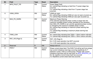
// Bit7: MFR_FAULT_PS (Power stage fault - latched)
if (status & MFR_FAULT_PS_MASK)
{
printf("- Bit7 (MFR_FAULT_PS): Power stage fault detected (latched).\n");
}
// Bit6: VSNS_OPEN (VSNS pin open - latched)
if (status & VSNS_OPEN_MASK)
{
printf("- Bit6 (VSNS_OPEN): VSNS pin open detected (latched)\n");
}
// Bit5: MAX_PH_WARN (Max phase warning - latched)
if (status & MAX_PH_WARN_MASK)
{
printf("- Bit5 (MAX_PH_WARN): Max phase count exceeded (latched).\n");
}
// Bit4: TSNS_LOW (TSEN ≥ 150mV before soft start)
if (status & TSNS_LOW_MASK)
{
printf("- Bit4 (TSNS_LOW): TSEN voltage high before soft start.\n");
}
// Bit3: RST_VID (VID reset occurred)
if (status & RST_VID_MASK)
{
printf("- Bit3 (RST_VID): VID reset executed (Page 0 only).\n");
}
// Bit2~1: Reserved (should be 0)
if ((status & 0x06) != 0)
{
printf("- Bit2~1: Reserved bits set unexpectedly (0x%02X).\n", status & 0x06);
}
// Bit0: PHFLT (Phase current sharing fault - latched)
if (status & PHFLT_MASK)
{
printf("- Bit0 (PHFLT): Phase current sharing fault detected (latched).\n");
}
return 0;
}
int deal_status_reg(uint8_t addr)
{
int ret;
switch (addr)
{
case REG_STATUS_BYTE:
ret = parse_status_byte(addr);
break;
case REG_STATUS_WORD:
ret = parse_status_word(addr);
break;
case REG_STATUS_VOUT:
ret = parse_status_vout(addr);
break;
case REG_STATUS_IOUT:
ret = parse_status_iout(addr);
break;
case REG_STATUS_INPUT:
ret = parse_status_input(addr);
break;
case REG_STATUS_TEMP:
ret = parse_status_temperature(addr);
break;
case REG_STATUS_CML:
parse_status_cml(addr);
break;
case REG_STATUS_MFR_SPECIFIC:
ret = parse_status_mfr_specific(addr);
break;
default:
break;
}
}
int check_status_error_(void)
{
int i;
for (i = 0; i < status_regs_count; i++)
{
/* code */
}
}
// 5mV 步进模式的 VID 转电压
int vid_to_voltage_5mv(int val)
{
if (val < 1 || val > 0xFF)
{
return 0; // 返回 0 表示无效
}
return 250 + (val - 1) * 5;
}
int16_t voltage_to_vid_5mv(uint16_t value)
{
// 电压小于 250mV,无效,返回 VID = 0
if (value < 250)
{
return 0;
}
// 向上取整到最接近的 5mV
value = (value + 4) / 5 * 5;
// 计算 VID
uint8_t vid = (value - 250) / 5 + 1;
// 如果 VID 超出有效范围,返回最大 VID (0xFF)
return (vid > 0xFF) ? 0xFF : vid;
}
/**
* @description: 设置 VR_MODE 为 5mV 模式的函数
* @return {*}
*/
int set_5mv_dac_mode(void)
{
uint8_t current_value[2];
// 读取 MFR_SPECIFIC_13 寄存器的当前值
if (read_from_reg(MFR_SPECIFIC_13, current_value, sizeof(current_value)) != 0)
{
return -1;
}
// 清除 VR_MODE 位(位 7 - 5)
current_value[0] &= ~(0x07 << 5);
// 设置 VR_MODE 为 5mV 模式(0x07 << 5)
current_value[1] |= (0x07 << 5);
// 将修改后的值写回 MFR_SPECIFIC_13 寄存器
if (write_to_reg(MFR_SPECIFIC_13, current_value, sizeof(current_value)) != 0)
{
return -1;
}
return 0;
}
/** tps53681 该寄存器默认为21 5mv模式
* @description: 先获取确认是5mv, 不是重新设置输出电压的步长
* @return {*}
*/
VoutMode set_vout_mode(void)
{
uint8_t status = 0;
if (read_from_reg(VOUT_MODE_REG, &status, sizeof(status)) != 0)
{
// 处理I2C读取错误
return -1;
}
printf(" status %d\n", status);
if (status == VOUT_MODE_5MV)
{
return VOUT_MODE_5MV;
}
set_5mv_dac_mode();
return VOUT_MODE_5MV;
}
/**
* @description: 设置警报掩码的函数
* @param {uint8_t} status_reg_addr
* @param {uint8_t} offset
* @return {*}
*/
void set_alert_mask(uint8_t status_reg_addr, uint8_t offset)
{
uint8_t reg[3];
if (read_from_reg(SMBALERT_MASK_REGISTER, ®[2], 1) != 0)
{
// return -1;
}
reg[0] = SMBALERT_MASK_REGISTER;
reg[1] = status_reg_addr;
reg[2] |= 1 << offset;
write_to_reg(SMBALERT_MASK_REGISTER, reg, sizeof(reg));
}
/**
* @description: // 禁止 STATUS_VOUT 中的欠压故障
* @return {*}
*/
void disable_under_voltage(void)
{
set_alert_mask(STATUS_VOUT_REGISTER, 4);
}
void set_phase_num(uint8_t page, uint8_t num)
{
write_to_reg(PAGE_REGISTER, &page, 1);
write_to_reg(MFR_PHASE_CONFIG_REGISTER, &num, 1);
}
uint16_t current_to_register_value(uint16_t current)
{
uint8_t exp = 0;
uint16_t reg_value;
if (current >= 0x07FF)
{
// 如果超出范围,将电流值设置为尾数位能表示的最大值 单位A
current = 0x07FF;
}
// 组合指数和尾数,指数位全 0 时,直接用尾数表示电流值
reg_value = (exp << 11) | current;
return reg_value;
}
/**
* @description: 选择通道A、B
* @param {uint8_t} page 0:A, 1:B
* @return {*}
*/
void select_page(uint8_t page)
{
write_to_reg(PAGE_REGISTER, &page, 1);
}
/**
* @description: 输出电流的过流阈值
* @param {uint8_t} addr
* @param {uint16_t} current
* @return {*}
*/
int8_t set_register_bit10(uint8_t addr, uint16_t current)
{
uint16_t value = current_to_register_value(current);
return write_to_reg(addr, (uint8_t *)&value, sizeof(value));
}
int16_t set_vout_register(uint16_t value)
{
int16_t voltage;
voltage = voltage_to_vid_5mv(value);
printf("set voltage:%02x\n", voltage);
return write_to_reg(VOUT_COMMAND_REGISTER, &voltage, sizeof(voltage));
}
// 配置 MFR_SPECIFIC_13 寄存器的 VR_MODE 和 OTF_DFLT 位
int8_t configure_mfr_specific_13(uint8_t vr_mode, uint8_t otf_dflt)
{
uint16_t current_value;
uint16_t new_value;
if (vr_mode || otf_dflt)
{
return -1;
}
// 读取当前寄存器值
read_from_reg(MFR_SPECIFIC_13, (uint8_t *)¤t_value, sizeof(current_value)); // todo 有一样的
// 仅当参数非零时设置对应位
if (vr_mode)
{
// 清除目标位(VR_MODE和OTF_DFLT)
current_value &= ~(0x07 << 5); // 清除位7-5
new_value |= (vr_mode << 5); // 设置VR_MODE(位7-5)
}
if (otf_dflt)
{
current_value &= ~(0x01 << 11); // 清除位11
new_value |= (otf_dflt << 11); // 设置OTF_DFLT(位11)
}
// 初始化new_value为清除后的当前值
new_value = current_value;
// 写入新的值到寄存器
write_to_reg(MFR_SPECIFIC_13, (uint8_t *)&new_value, sizeof(new_value));
return 0;
}
// 配置 MFR_SPECIFIC_10
/**
* @description: 设置最大输出电流 单位1A
* @param {uint8_t} max_electr
* @return {*}
*/
void configure_mfr_specific_10(uint8_t max_electr)
{
uint8_t current_value[2] = {0};
// 读取当前寄存器值
read_from_reg(MFR_SPECIFIC_10, current_value, sizeof(current_value));
// 清除目标位
current_value[0] &= ~(0xFF); // 清除低8bit
// 设置新的值
current_value[0] = max_electr;
// 写入新的值到寄存器
write_to_reg(MFR_SPECIFIC_10, current_value, sizeof(current_value));
}
// 定期读取电压电流函数
// void Monitor_Parameters(void)
// {
// uint8_t vout_data[2];
// uint8_t iout_data[2];
// read_from_reg(CMD_READ_VOUT, vout_data, sizeof(vout_data));
// printf("Vout: Read data, need conversion\n");
// read_from_reg(CMD_READ_IOUT, iout_data, sizeof(iout_data));
// printf("Iout: Read data, need conversion\n");
// }
#if 0
void configure_chip(void)
{
select_page(0); // 选择通道 A
set_vout_mode(); // 先获取是什么数值,获取模式
set_vout_register(VOUT_COMMAND_REGISTER, 1000); // 设置1000mv,对应vid为0x9700
write_to_reg(VOUT_UV_FAULT_RESPONSE, &(0XBA), 1); // 欠压响应 默认0x80
configure_mfr_specific_10(10); // 设置过流阈值 10A
set_register_bit10(IOUT_OC_FAULT_LIMIT, 10); // 10:0 1A
set_register_bit10(IOUT_OC_WARN_LIMIT, 255); // 10:0 1A 根据FPGA的供电电流配置 // 设置过流阈值警告 最大255A 单位1A
write_to_reg(IOUT_OC_FAULT_RESPONSE,&(0xC0), 1); // 响应输出过流故障
configure_mfr_specific_13(NONE, NONE);
set_register_bit10(OT_FAULT_LIMIT, 0x80); // 设置最大温度 //10:0 默认135
set_register_bit10(OT_WARN_LIMIT, 0x69); // 默认105度 // 设置警告温度
write_to_reg(OT_FAULT_RESPONSE_REG, &(0x80), 1); // 设置过温处理
// 使能 OPERATION 命令控制
write_to_reg(ON_OFF_CONFIG_REGISTER, &(0x1B), 1);
// 开启输出
write_to_reg(OPERATION_REGISTER, &(0x80), 1);
// write_to_reg(OPERATION_REGISTER, 0x00,1);//关闭
}
#endif
void configure_chip(void)
{
uint8_t data;
select_page(0); // 选择通道 A
// set_vout_mode(); // 先获取是什么数值,获取模式
// set_vout_register(VOUT_COMMAND_REGISTER, 1000); // 设置输出电压为1000mv
data = 0XBA;
write_to_reg(VOUT_UV_FAULT_RESPONSE, &data, 1); // 欠压响应 默认0x80 关机不重启, 欠压芯片20ms后重启
configure_mfr_specific_10(10); // 设置最大输出电流 10A
set_register_bit10(IOUT_OC_FAULT_LIMIT, 10); // 过流阈值
set_register_bit10(IOUT_OC_WARN_LIMIT, 255); // 10:0 1A 根据FPGA的供电电流配置 // 设置过流阈值警告 最大255A 单位1A
data = 0xC0;
write_to_reg(IOUT_OC_FAULT_RESPONSE, &data, 1); // 响应输出过流故障
// configure_mfr_specific_13(NONE, NONE);
set_register_bit10(OT_FAULT_LIMIT, 0x80); // 设置最大温度 //10:0 默认135
set_register_bit10(OT_WARN_LIMIT, 0x69); // 默认105度 // 设置警告温度
data = 0x80;
write_to_reg(OT_FAULT_RESPONSE_REG, &data, 1); // 设置过温处理
// 使能 OPERATION 命令控制
data = 0x1B;
write_to_reg(ON_OFF_CONFIG_REGISTER, &data, 1);
// 开启输出
data = 0x80;
write_to_reg(OPERATION_REGISTER, &data, 1);
// write_to_reg(OPERATION_REGISTER, 0x00,1);//关闭
}
// 分隔线打印(固定格式)
static void print_separator(void)
{
printf("\n+++++++++++++++++++++++++++++++++++++\n");
}
// 操作头信息打印(通用标题)
static void print_operation_header(const char *op_type, uint8_t reg, uint8_t len)
{
printf("======= %s: reg=0x%02X, len=%d\n", op_type, reg, len);
}
// 缓冲区内容打印(通用数组打印)
static void print_buffer(const char *buf_type, uint8_t reg, uint8_t len, const uint8_t *buf)
{
uint8_t i;
for (i = 0; i < len; i++)
{
printf("%s[%d] = 0x%02X ", buf_type, i, buf[i]);
if (i == len - 1)
{
printf("\n");
}
}
}
void reg_test(uint8_t reg, uint8_t *buf, uint8_t len)
{
uint8_t value[2], i; // 注意:原逻辑限制最大长度为2字节(sizeof(value)=2)
uint8_t value2[2] = {0};
// 长度校验(保持原有逻辑)
if (len > sizeof(value))
{
printf("[ERROR] len (%d) exceeds buffer size\n", len);
return;
}
print_separator(); // 顶部分隔线
// 读取原始值
print_operation_header("before write", reg, len);
read_from_reg(reg, value, len);
print_buffer("read", reg, len, value);
// 写入新值
print_operation_header("to reg", reg, len);
print_buffer("write", reg, len, buf);
write_to_reg(reg, buf, len);
// 验证写入结果
print_operation_header("after write", reg, len);
read_from_reg(reg, value2, len);
print_buffer("read", reg, len, value2);
print_separator(); // 底部分隔线
}
void page_test(void)
{
uint8_t page = 0, data = 0;
uint8_t buf2[2] = {0};
uint16_t vid;
reg_test(PAGE_REGISTER, &page, 1);
}
void out_voltage(void)
{
uint8_t page = 0, data = 0;
uint8_t buf2[2] = {0};
uint16_t vid;
vid = voltage_to_vid_5mv(360);
buf2[0] = (uint8_t)(vid & 0xFF); // low byte
buf2[1] = (uint8_t)(vid >> 8); // high byte
printf("VID=0x%04X, buf: %02x, %02x\n", vid, buf2[0], buf2[1]);
reg_test(VOUT_COMMAND_REGISTER, buf2, 2);
}
void enable_test(void)
{
uint8_t page = 0, data = 0;
uint8_t buf2[2] = {0};
uint16_t vid;
data = 0x80;
reg_test(OPERATION_REGISTER, &data, 1);
}
void get_out_mode(void)
{
uint8_t mode = 0;
read_from_reg(VOUT_MODE_REG, &mode, 1);
printf("mode %02x\n", mode);
}
void get_on_off_config(void)
{
uint8_t mode = 0;
read_from_reg(ON_OFF_CONFIG_REGISTER, &mode, 1);
printf("ON_OFF_CONFIG %02x\n", mode);
}
void get_up_rate(void)
{
uint8_t buf2[2] = {0};
read_from_reg(VOUT_RATE_REG, buf2, 2);
printf("VOUT_RATE_REG=0x%04X, buf: %02x, %02x\n", VOUT_RATE_REG, buf2[0], buf2[1]);
}
void get_vout_fault_limit(void)
{
uint8_t buf2[2] = {0};
read_from_reg(VOUT_OV_FAULT_LIMIT, buf2, 2);
printf("VOUT_OV_FAULT_LIMIT=0x%04X, buf: %02x, %02x\n", VOUT_OV_FAULT_LIMIT, buf2[0], buf2[1]);
}
void MFR_SPECIFIC_13_test(void)
{
uint8_t page = 0, data = 0;
uint8_t buf2[2] = {0};
uint16_t vid;
// read_from_reg(MFR_SPECIFIC_13, buf2, 2);
// printf("MFR_SPECIFIC_13=0x%04X, buf: %02x, %02x\n", MFR_SPECIFIC_13, buf2[0], buf2[1]);
// buf2[0] = 0xE5; // low byte
// buf2[1] = 0x88; // high byte 89 1/16 88 1/4
// printf("MFR_SPECIFIC_13: %02x, buf: %02x, %02x\n", MFR_SPECIFIC_13, buf2[0], buf2[1]);
// reg_test(MFR_SPECIFIC_13, buf2, 2);
read_from_reg(MFR_SPECIFIC_13, buf2, 2);
printf("MFR_SPECIFIC_13: %02x, buf: %02x, %02x\n", MFR_SPECIFIC_13, buf2[0], buf2[1]);
}
// 读取输出电压(单位 mV,LSB = 0.625mV,适用于 Intel VR13 模式)
int tps53681_read_vout_voltage(void)
{
uint16_t raw = 0;
read_from_reg(READ_VOUT_REG, &raw, 2);
print_buffer(" vout", READ_VOUT_REG, 2, &raw);
return 0;
}
// 读取芯片温度(单位 °C,LSB = 0.125°C)
int tps53681_read_temperature()
{
uint16_t raw;
read_from_reg(READ_TEMPER_REG, &raw, 2);
print_buffer(" temper", READ_TEMPER_REG, 2, &raw);
return 0;
}
// 读取某个相位的输出电流(单位 A,LSB = 0.125A)
// int tps53681_read_iout_phase(uint8_t phase, float *current)
// {
// if (phase >= TPS53681_MAX_PHASES)
// return -1;
// if (tps_set_page(0) < 0)
// return -1;
// // 设置 PHASE = 0x80 | phase
// if (tps_i2c_write_byte(PMBUS_PHASE, 0x80 | (phase & 0x0F)) < 0)
// return -1;
// uint16_t raw;
// if (tps_i2c_read_word(PMBUS_READ_IOUT, &raw) < 0)
// return -1;
// *current = raw * 0.125f;
// return 0;
// }
// 读取总输出电流(phase 设置为 0x80 表示全部相位)
int tps53681_read_iout_total(void)
{
uint16_t raw = 0;
uint8_t cmd = 0x80;
write_to_reg(MFR_PHASE_CONFIG_REGISTER, &cmd, 1);
read_from_reg(READ_IOUT_REG, &raw, 2);
return 0;
}
// int tps53681_init1(void)
// {
// gpio_init(TPS53681_AVREN_PORT, GPIO_MODE_OUT_PP, GPIO_OSPEED_50MHZ, TPS53681_AVREN_PIN);
// gpio_bit_reset(TPS53681_AVREN_PORT, TPS53681_AVREN_PIN);
// return 0;
// }
void clear_error(void)
{
uint16_t num = 0x0000;
write_to_reg(CLERA_FAULT_REG, &num, 2);
}
void tps53681_init(void)
{
page_test();
// clear_error();
// parse_status_word(REG_STATUS_WORD);
// MFR_SPECIFIC_13_test();
get_on_off_config(); // ON_OFF_CONFIG 1B
get_out_mode(); // mode 21
// get_up_rate();
// get_vout_fault_limit();
// tps53681_read_temperature();
out_voltage();
enable_test();
parse_status_byte(REG_STATUS_BYTE);
parse_status_word(REG_STATUS_WORD);
parse_status_mfr_specific(REG_STATUS_MFR_SPECIFIC);
tps53681_read_vout_voltage();
}
// void tps53681_init(void)
// {
// uint8_t page = 0, value[2] = {0}, data = 0;
// uint16_t voltage = 0;
// reg_test(PAGE_REGISTER, &page, 1);
// printf("====== page 0 ======\n");
// reg_test(PAGE_REGISTER, &page, 1);
// voltage = voltage_to_vid_5mv(800);
// value[0] = voltage & 0xFF;
// value[1] = voltage >> 8;
// printf(" set voltage :%02x", voltage);
// reg_test(VOUT_COMMAND_REGISTER, &value, 2);
// // 开启输出 // 使能 OPERATION 命令控制
// data = 0x80;
// reg_test(OPERATION_REGISTER, &data, 1);
// printf("====== enable ======\n");
// // disable_under_voltage();
// // configure_chip();
// }
void reset_chip(void)
{
// MCU PA15
// 警报 PA1
}
======= before write: reg=0x00, len=1
read[0] = 0x00
======= to reg: reg=0x00, len=1
write[0] = 0x00
======= after write: reg=0x00, len=1
read[0] = 0x00

+++++++++++++++++++++++++++++++++++++
ON_OFF_CONFIG  1b
mode  21
 temper[0] = 0xAC  temper[1] = 0xE2
VID=0x0017, buf: 17, 00

+++++++++++++++++++++++++++++++++++++
======= before write: reg=0x21, len=2
read[0] = 0x17 read[1] = 0x00
======= to reg: reg=0x21, len=2
write[0] = 0x17 write[1] = 0x00
======= after write: reg=0x21, len=2
read[0] = 0x17 read[1] = 0x00

+++++++++++++++++++++++++++++++++++++

+++++++++++++++++++++++++++++++++++++
======= before write: reg=0x01, len=1
read[0] = 0x80
======= to reg: reg=0x01, len=1
write[0] = 0x80
======= after write: reg=0x01, len=1
read[0] = 0x80

+++++++++++++++++++++++++++++++++++++
status_byte: not providing power to VOUT: 41
status_byte: Unclassified fault (e.g., UVF, OCW; check other status registers)
status_word: value: 0x1841 (Bytes: 0x41 0x18)
status_word: MFR bit warning
status_word: Power NOT good (AVR_RDY/BVR_RDY pin is LOW)
status_word: Not providing power to VOUT
status_word: Unclassified fault detected
MFR_SPECIFIC_STATUS: 0x40
- Bit6 (VSNS_OPEN): VSNS pin open detected (latched)
 vout[0] = 0x00  vout[1] = 0x00