This thread has been locked.

If you have a related question, please click the "Ask a related question" button in the top right corner. The newly created question will be automatically linked to this question.

CCS如何生成正确的HEX文件

Other Parts Discussed in Thread: CC1312R, UNIFLASH

各位工程师你们好,

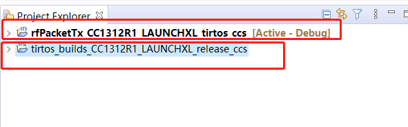
我使用的芯片为CC1312R,SDK版本为simplelink_cc13x2_26x2_sdk_4_20_00_35,CCS版本为Version: 10.1.0.00010,使用的例程为rfPacketTx。

目前烧录情况为:

(1)使用XDS在CCS内进行烧录,能够成功烧录且正常运行;

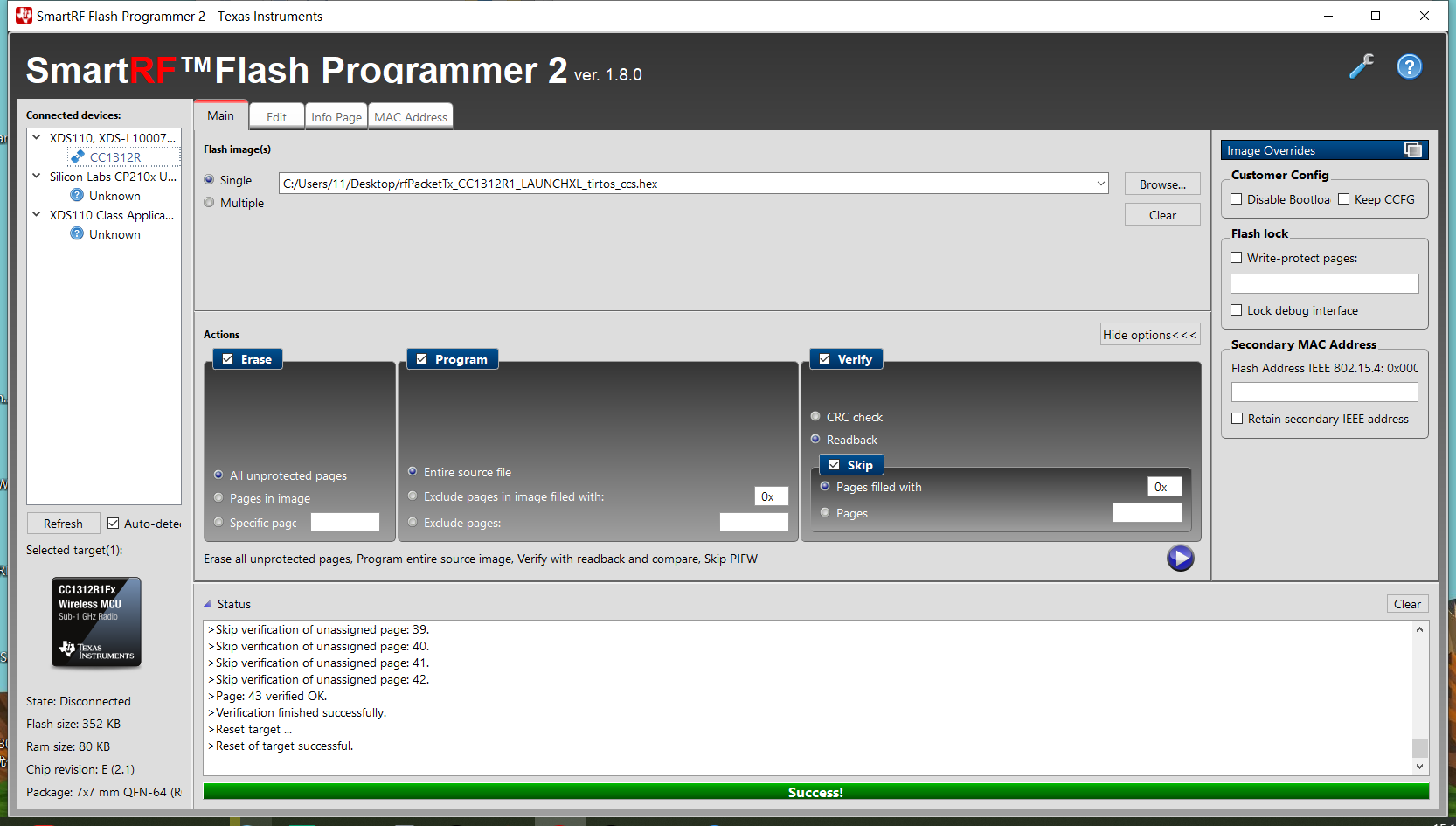
(2)将编译生成的.out文件通过flash programmer2进行烧录,也能成功烧录且正常运行;

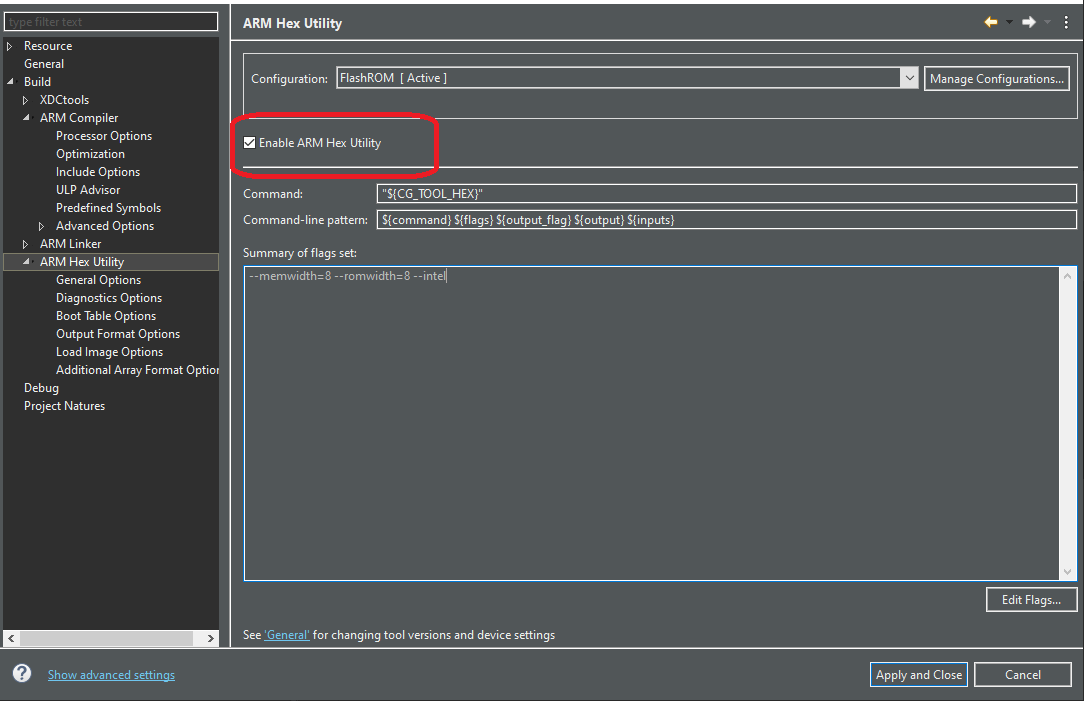
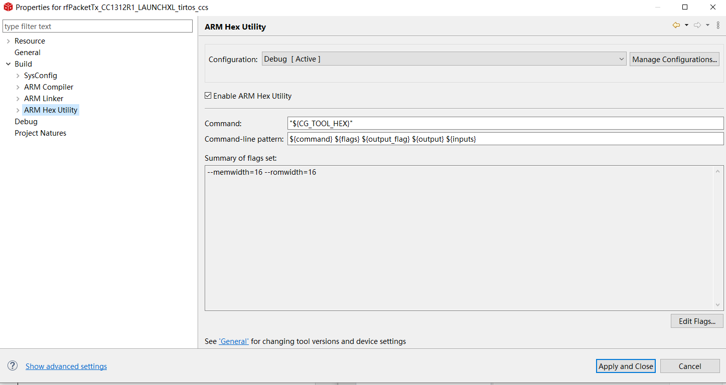
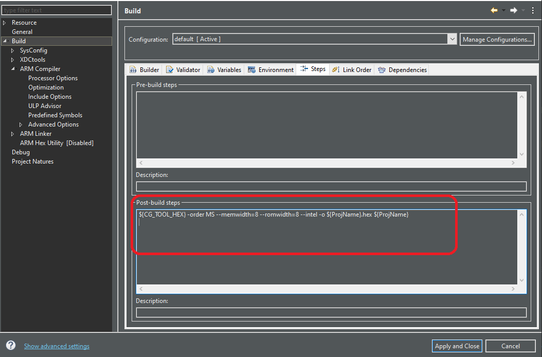
(3)将工程配置为生成HEX文件,生成的HEX文件烧录入芯片后,程序没有正常运行;

我的猜测为由于我使用了官方的TI-RTOS,因此工作面板中有两个工程,分别为rfPacketTx和tirtos的工程,而我仅配置rfPacketTx生成HEX,因此生成的HEX是不完整的,无法实现正常的功能?不知道我的理解是否正确,请问我应该如何操作让其生成正确的HEX?

  • 你是在哪里配置生成hex文件的?是否是通过下面方式

  • 我勾选了Enable ARM Hex Utility,但是我发现configuration一栏,我的Configuration选项与您的配置不一样。

  • 看下这里是否有命令

  • 我这里没有此条语句,我是增添这条语句就可以了吗?是否还需要其他操作?
  • 你先加上这句试一下:${CG_TOOL_HEX} -order MS --memwidth=8 --romwidth=8 --intel -o ${ProjName}.hex ${ProjName}
  • 按照您的描述我添加了此条语句,但是发现在CCS里面烧录程序时,设备最后发送数据以后能按照流程进入低功耗(5uA),而烧录HEX时,只是能发送数据,但不能正常进入低功耗(442uA),请问这可能是由于什么原因引起的呢?
  • 一般按第一种方法就可以了,可能是编译器的原因。修改完重新编译下,你是用什么烧录程序的?
    用下面命令生成bin文件试试:${CG_TOOL_ROOT}/bin/armobjcopy -O binary --only-section .text --only-section .const --only-section .cinit --only-section .resetVecs ${BuildArtifactFileName} ${BuildArtifactFileBaseName}.bin
  •  我烧录的HEX是已经重新编译了的,即为上述效果。按照您给的命令生成的bin文件烧录以后,发送数据功能以及低功耗功能都无法实现。我使用SmartRF Flash Programmer 2进行烧录的。

  • 您好, 我发现使用smartrf programmer 2烧录.out文件,设备也无法进入低功耗(440uA),但是在CCS工程中进行烧录,可以进入低功耗(5uA),请问该如何解决此问题呢?
  • 你在程序中做了哪些修改,按下复位试试
  • 我测试了5个设备,重新上电也测试了很多次,现象都是使用programmer 2烧录程序.out/.hex时,无法进入低功耗,但在CCS中烧录就可以进入低功耗。我在程序中增加了无线数据的发送以及无线数据的接收,接收到指定的数据包后,进入低功耗。
  • 你把修改的代码传上来,我将咨询这方面的专家,得到回复会立即回复给你。
  • /*
     * Copyright (c) 2019, Texas Instruments Incorporated
     * All rights reserved.
     *
     * Redistribution and use in source and binary forms, with or without
     * modification, are permitted provided that the following conditions
     * are met:
     *
     * *  Redistributions of source code must retain the above copyright
     *    notice, this list of conditions and the following disclaimer.
     *
     * *  Redistributions in binary form must reproduce the above copyright
     *    notice, this list of conditions and the following disclaimer in the
     *    documentation and/or other materials provided with the distribution.
     *
     * *  Neither the name of Texas Instruments Incorporated nor the names of
     *    its contributors may be used to endorse or promote products derived
     *    from this software without specific prior written permission.
     *
     * THIS SOFTWARE IS PROVIDED BY THE COPYRIGHT HOLDERS AND CONTRIBUTORS "AS IS"
     * AND ANY EXPRESS OR IMPLIED WARRANTIES, INCLUDING, BUT NOT LIMITED TO,
     * THE IMPLIED WARRANTIES OF MERCHANTABILITY AND FITNESS FOR A PARTICULAR
     * PURPOSE ARE DISCLAIMED. IN NO EVENT SHALL THE COPYRIGHT OWNER OR
     * CONTRIBUTORS BE LIABLE FOR ANY DIRECT, INDIRECT, INCIDENTAL, SPECIAL,
     * EXEMPLARY, OR CONSEQUENTIAL DAMAGES (INCLUDING, BUT NOT LIMITED TO,
     * PROCUREMENT OF SUBSTITUTE GOODS OR SERVICES; LOSS OF USE, DATA, OR PROFITS;
     * OR BUSINESS INTERRUPTION) HOWEVER CAUSED AND ON ANY THEORY OF LIABILITY,
     * WHETHER IN CONTRACT, STRICT LIABILITY, OR TORT (INCLUDING NEGLIGENCE OR
     * OTHERWISE) ARISING IN ANY WAY OUT OF THE USE OF THIS SOFTWARE,
     * EVEN IF ADVISED OF THE POSSIBILITY OF SUCH DAMAGE.
     */
    
    /***** Includes *****/
    /* Standard C Libraries */
    #include <stdlib.h>
    #include <unistd.h>
    
    /* TI Drivers */
    #include <ti/drivers/rf/RF.h>
    #include <ti/drivers/PIN.h>
    #include <ti/drivers/pin/PINCC26XX.h>
    #include <ti/drivers/UART.h>
    #include <ti/drivers/SPI.h>
    /* Driverlib Header files */
    #include DeviceFamily_constructPath(driverlib/rf_prop_mailbox.h)
    
    /* Board Header files */
    #include "ti_drivers_config.h"
    #include "RFQueue.h"
    #include <ti_radio_config.h>
    
    #include "de_bug.h"
    #include "ebyte_mx25r2035f.h"
    /***** Defines *****/
    
    static void callback(RF_Handle h, RF_CmdHandle ch, RF_EventMask e);
    
    /* Receive dataQueue for RF Core to fill in data */
    static dataQueue_t dataQueue;
    static rfc_dataEntryGeneral_t* currentDataEntry;
    static uint8_t packetLength;
    static uint8_t receLenth;
    static uint8_t* packetDataPointer;
    /* Packet RX Configuration */
    #define DATA_ENTRY_HEADER_SIZE 8  /* Constant header size of a Generic Data Entry */
    #define MAX_LENGTH             30 /* Max length byte the radio will accept */
    #define NUM_DATA_ENTRIES       2  /* NOTE: Only two data entries supported at the moment */
    #define NUM_APPENDED_BYTES     2  /* The Data Entries data field will contain:
                                       * 1 Header byte (RF_cmdPropRx.rxConf.bIncludeHdr = 0x1)
                                       * Max 30 payload bytes
                                       * 1 status byte (RF_cmdPropRx.rxConf.bAppendStatus = 0x1) */
    
    /* Buffer which contains all Data Entries for receiving data.
     * Pragmas are needed to make sure this buffer is 4 byte aligned (requirement from the RF Core) */
    #if defined(__TI_COMPILER_VERSION__)
    #pragma DATA_ALIGN (rxDataEntryBuffer, 4);
    static uint8_t
    rxDataEntryBuffer[RF_QUEUE_DATA_ENTRY_BUFFER_SIZE(NUM_DATA_ENTRIES,
                                                      MAX_LENGTH,
                                                      NUM_APPENDED_BYTES)];
    #elif defined(__IAR_SYSTEMS_ICC__)
    #pragma data_alignment = 4
    static uint8_t
    rxDataEntryBuffer[RF_QUEUE_DATA_ENTRY_BUFFER_SIZE(NUM_DATA_ENTRIES,
                                                      MAX_LENGTH,
                                                      NUM_APPENDED_BYTES)];
    #elif defined(__GNUC__)
    static uint8_t
    rxDataEntryBuffer[RF_QUEUE_DATA_ENTRY_BUFFER_SIZE(NUM_DATA_ENTRIES,
                                                      MAX_LENGTH,
                                                      NUM_APPENDED_BYTES)]
                                                      __attribute__((aligned(4)));
    #else
    #error This compiler is not supported.
    #endif
    
    /* Packet TX Configuration */
    #define PAYLOAD_LENGTH      10
    #ifdef POWER_MEASUREMENT
    #define PACKET_INTERVAL     5  /* For power measurement set packet interval to 5s */
    #else
    #define PACKET_INTERVAL     500000  /* Set packet interval to 500000us or 500ms */
    #endif
    
    uint8_t RecevFlag = 0;
    /***** Prototypes *****/
    
    /***** Variable declarations *****/
    UART_Handle uart;
    UART_Params uartParams;
    #define     OPEN_USART_IDLE         UART_CMD_RESERVED + 0    //UARTCC26XX_CMD_RETURN_PARTIAL_DISABLE
    
    
    static RF_Object rfObject;
    static RF_Handle rfHandle;
    RF_Params rfParams;
    static RF_CmdHandle rf_cmdhandle = NULL;
    
    /* Pin driver handle */
    //static PIN_Handle ModePinHandle;
    //static PIN_State ModePinState;
    //
    //static PIN_Handle LEDPinHandle;
    //static PIN_State LEDPinState;
    //
    //static PIN_Handle LEDConnectPinHandle;
    //static PIN_State LEDConnectPinState;
    
    /*   pin test */
    static PIN_Handle testPinHandle1;
    static PIN_State testPinState1;
    
    static PIN_Handle testPinHandle2;
    static PIN_State testPinState2;
    
    
    static PIN_Handle testPinHandle3;
    static PIN_State testPinState3;
    
    static PIN_Handle testPinHandle4;
    static PIN_State testPinState4;


    static uint8_t power_packet[PAYLOAD_LENGTH] =  {1,2,3,4,5,6,7,8,9,0};
    
    static uint8_t trans_packet[PAYLOAD_LENGTH] = {0,9,8,7,6,5,4,3,2,1};
    
    static uint8_t recePacket[PAYLOAD_LENGTH] = {2,11,10,9,8,7,6,5,4,3};
    static uint8_t checkPacket[PAYLOAD_LENGTH];
    //static uint8_t packet[PAYLOAD_LENGTH] =    {6,6,6,6,6,6,6,6,6,6,
    //                                            5,5,5,5,5,5,5,5,5,5,
    //                                            4,4,4,4,4,4,4,4,4,4};
    
    
    ///* PA Pin */
    //#define     PA_CPS_PIN      PIN_ID(7)
    //#define     PA_CSD_PIN      PIN_ID(5)
    //#define     PA_CTX_PIN      PIN_ID(6)
    //
    ///* Mode Pin */
    //#define     Mode_Sel_PIN    PIN_ID(4)
    
    ///* LED Pin */
    //#define     LED_PIN_1           PIN_ID(1)
    //#define     LED_CONNECT_PIN_30  PIN_ID(30)


    //PIN_Config ModepinTable[] =
    //{
    //     Mode_Sel_PIN |  PIN_INPUT_EN | PIN_PULLUP,
    //     PIN_TERMINATE
    //};
    //
    //PIN_Config LEDpinTable[] =
    //{
    //     LED_PIN_1 |  PIN_GPIO_OUTPUT_EN | PIN_GPIO_LOW | PIN_PUSHPULL | PIN_DRVSTR_MAX,
    //     PIN_TERMINATE
    //};
    
    //PIN_Config LEDConnectpinTable[] =
    //{
    // LED_CONNECT_PIN_30 |  PIN_GPIO_OUTPUT_EN | PIN_GPIO_LOW | PIN_PUSHPULL | PIN_DRVSTR_MAX,
    //     PIN_TERMINATE
    //};
    
    
    /* pin test */
    
    PIN_Config testPinTable1[] = {
                Pin_19  | PIN_GPIO_OUTPUT_EN | PIN_GPIO_LOW | PIN_PUSHPULL | PIN_DRVSTR_MAX,
                Pin_1   |  PIN_INPUT_EN | PIN_NOPULL,
    
                Pin_20  | PIN_GPIO_OUTPUT_EN | PIN_GPIO_HIGH | PIN_PUSHPULL | PIN_DRVSTR_MAX,
                Pin_2   |  PIN_INPUT_EN | PIN_NOPULL,
    
                Pin_21  | PIN_GPIO_OUTPUT_EN | PIN_GPIO_LOW | PIN_PUSHPULL | PIN_DRVSTR_MAX,
                Pin_3   |  PIN_INPUT_EN | PIN_NOPULL,
    
                Pin_22  | PIN_GPIO_OUTPUT_EN | PIN_GPIO_HIGH | PIN_PUSHPULL | PIN_DRVSTR_MAX,
                Pin_4  |  PIN_INPUT_EN | PIN_NOPULL,
    
                Pin_23  | PIN_GPIO_OUTPUT_EN | PIN_GPIO_LOW | PIN_PUSHPULL | PIN_DRVSTR_MAX,
                Pin_5   |  PIN_INPUT_EN | PIN_NOPULL,
    
                Pin_24  | PIN_GPIO_OUTPUT_EN | PIN_GPIO_HIGH | PIN_PUSHPULL | PIN_DRVSTR_MAX,
                Pin_6  |  PIN_INPUT_EN | PIN_NOPULL,
    
                Pin_25  | PIN_GPIO_OUTPUT_EN | PIN_GPIO_LOW | PIN_PUSHPULL | PIN_DRVSTR_MAX,
                Pin_7  |  PIN_INPUT_EN | PIN_NOPULL,
    
                Pin_26  | PIN_GPIO_OUTPUT_EN | PIN_GPIO_HIGH | PIN_PUSHPULL | PIN_DRVSTR_MAX,
                Pin_8  |  PIN_INPUT_EN | PIN_NOPULL,
    
                Pin_27  | PIN_GPIO_OUTPUT_EN | PIN_GPIO_LOW | PIN_PUSHPULL | PIN_DRVSTR_MAX,
                Pin_9  |  PIN_INPUT_EN | PIN_NOPULL,
    
                Pin_28  | PIN_GPIO_OUTPUT_EN | PIN_GPIO_HIGH | PIN_PUSHPULL | PIN_DRVSTR_MAX,
                Pin_10  |  PIN_INPUT_EN | PIN_NOPULL,
    
                Pin_29  | PIN_GPIO_OUTPUT_EN | PIN_GPIO_LOW | PIN_PUSHPULL | PIN_DRVSTR_MAX,
                Pin_16  |  PIN_INPUT_EN | PIN_NOPULL,
    
                Pin_30  | PIN_GPIO_OUTPUT_EN | PIN_GPIO_HIGH | PIN_PUSHPULL | PIN_DRVSTR_MAX,
                Pin_17  |  PIN_INPUT_EN | PIN_NOPULL,
    
                //add pin test
                Pin_14  | PIN_GPIO_OUTPUT_EN | PIN_GPIO_LOW | PIN_PUSHPULL | PIN_DRVSTR_MAX,
                Pin_11  |  PIN_INPUT_EN | PIN_NOPULL,
    
                Pin_15  | PIN_GPIO_OUTPUT_EN | PIN_GPIO_HIGH | PIN_PUSHPULL | PIN_DRVSTR_MAX,
                Pin_13  |  PIN_INPUT_EN | PIN_NOPULL,
    
                Pin_18  | PIN_GPIO_OUTPUT_EN | PIN_GPIO_LOW | PIN_PUSHPULL | PIN_DRVSTR_MAX,
                Pin_12  |  PIN_INPUT_EN | PIN_NOPULL,
    
                PIN_TERMINATE
    
    };
    
    //second
    PIN_Config testPinTable2[] = {
              Pin_19  | PIN_GPIO_OUTPUT_EN | PIN_GPIO_HIGH | PIN_PUSHPULL | PIN_DRVSTR_MAX,
              Pin_1   |  PIN_INPUT_EN | PIN_PULLUP,
    
              Pin_20  | PIN_GPIO_OUTPUT_EN | PIN_GPIO_LOW | PIN_PUSHPULL | PIN_DRVSTR_MAX,
              Pin_2   |  PIN_INPUT_EN | PIN_PULLUP,
    
              Pin_21  | PIN_GPIO_OUTPUT_EN | PIN_GPIO_HIGH | PIN_PUSHPULL | PIN_DRVSTR_MAX,
              Pin_3   |  PIN_INPUT_EN | PIN_PULLUP,
    
              Pin_22  | PIN_GPIO_OUTPUT_EN | PIN_GPIO_LOW | PIN_PUSHPULL | PIN_DRVSTR_MAX,
              Pin_4  |  PIN_INPUT_EN | PIN_PULLUP,
    
              Pin_23  | PIN_GPIO_OUTPUT_EN | PIN_GPIO_HIGH | PIN_PUSHPULL | PIN_DRVSTR_MAX,
              Pin_5  |  PIN_INPUT_EN | PIN_PULLUP,
    
              Pin_24  | PIN_GPIO_OUTPUT_EN | PIN_GPIO_LOW | PIN_PUSHPULL | PIN_DRVSTR_MAX,
              Pin_6  |  PIN_INPUT_EN | PIN_PULLUP,
    
              Pin_25  | PIN_GPIO_OUTPUT_EN | PIN_GPIO_HIGH | PIN_PUSHPULL | PIN_DRVSTR_MAX,
              Pin_7  |  PIN_INPUT_EN | PIN_PULLUP,
    
              Pin_26  | PIN_GPIO_OUTPUT_EN | PIN_GPIO_LOW | PIN_PUSHPULL | PIN_DRVSTR_MAX,
              Pin_8  |  PIN_INPUT_EN | PIN_PULLUP,
    
              Pin_27  | PIN_GPIO_OUTPUT_EN | PIN_GPIO_HIGH | PIN_PUSHPULL | PIN_DRVSTR_MAX,
              Pin_9  |  PIN_INPUT_EN | PIN_PULLUP,
    
              Pin_28  | PIN_GPIO_OUTPUT_EN | PIN_GPIO_LOW | PIN_PUSHPULL | PIN_DRVSTR_MAX,
              Pin_10  |  PIN_INPUT_EN | PIN_PULLUP,
    
              Pin_29  | PIN_GPIO_OUTPUT_EN | PIN_GPIO_HIGH | PIN_PUSHPULL | PIN_DRVSTR_MAX,
              Pin_16  |  PIN_INPUT_EN | PIN_PULLUP,
    
              Pin_30  | PIN_GPIO_OUTPUT_EN | PIN_GPIO_LOW | PIN_PUSHPULL | PIN_DRVSTR_MAX,
              Pin_17  |  PIN_INPUT_EN | PIN_PULLUP,
    
              //add pin test
                Pin_14  | PIN_GPIO_OUTPUT_EN | PIN_GPIO_HIGH | PIN_PUSHPULL | PIN_DRVSTR_MAX,
                Pin_11  |  PIN_INPUT_EN | PIN_NOPULL,
    
                Pin_15  | PIN_GPIO_OUTPUT_EN | PIN_GPIO_LOW | PIN_PUSHPULL | PIN_DRVSTR_MAX,
                Pin_13  |  PIN_INPUT_EN | PIN_NOPULL,
    
                Pin_18  | PIN_GPIO_OUTPUT_EN | PIN_GPIO_HIGH | PIN_PUSHPULL | PIN_DRVSTR_MAX,
                Pin_12  |  PIN_INPUT_EN | PIN_NOPULL,
    
              PIN_TERMINATE
    };
    
    
    PIN_Config testPinTable3[] = {
                Pin_1  | PIN_GPIO_OUTPUT_EN | PIN_GPIO_LOW | PIN_PUSHPULL | PIN_DRVSTR_MAX,
                Pin_19   |  PIN_INPUT_EN | PIN_NOPULL,
    
                Pin_2  | PIN_GPIO_OUTPUT_EN | PIN_GPIO_HIGH | PIN_PUSHPULL | PIN_DRVSTR_MAX,
                Pin_20   |  PIN_INPUT_EN | PIN_NOPULL,
    
                Pin_3  | PIN_GPIO_OUTPUT_EN | PIN_GPIO_LOW | PIN_PUSHPULL | PIN_DRVSTR_MAX,
                Pin_21   |  PIN_INPUT_EN | PIN_NOPULL,
    
                Pin_4  | PIN_GPIO_OUTPUT_EN | PIN_GPIO_HIGH | PIN_PUSHPULL | PIN_DRVSTR_MAX,
                Pin_22  |  PIN_INPUT_EN | PIN_NOPULL,
    
                Pin_5  | PIN_GPIO_OUTPUT_EN | PIN_GPIO_LOW | PIN_PUSHPULL | PIN_DRVSTR_MAX,
                Pin_23   |  PIN_INPUT_EN | PIN_NOPULL,
    
                Pin_6  | PIN_GPIO_OUTPUT_EN | PIN_GPIO_HIGH | PIN_PUSHPULL | PIN_DRVSTR_MAX,
                Pin_24  |  PIN_INPUT_EN | PIN_NOPULL,
    
                Pin_7  | PIN_GPIO_OUTPUT_EN | PIN_GPIO_LOW | PIN_PUSHPULL | PIN_DRVSTR_MAX,
                Pin_25  |  PIN_INPUT_EN | PIN_NOPULL,
    
                Pin_8  | PIN_GPIO_OUTPUT_EN | PIN_GPIO_HIGH | PIN_PUSHPULL | PIN_DRVSTR_MAX,
                Pin_26  |  PIN_INPUT_EN | PIN_NOPULL,
    
                Pin_9  | PIN_GPIO_OUTPUT_EN | PIN_GPIO_LOW | PIN_PUSHPULL | PIN_DRVSTR_MAX,
                Pin_27  |  PIN_INPUT_EN | PIN_NOPULL,
    
                Pin_10  | PIN_GPIO_OUTPUT_EN | PIN_GPIO_HIGH | PIN_PUSHPULL | PIN_DRVSTR_MAX,
                Pin_28  |  PIN_INPUT_EN | PIN_NOPULL,
    
                Pin_16  | PIN_GPIO_OUTPUT_EN | PIN_GPIO_LOW | PIN_PUSHPULL | PIN_DRVSTR_MAX,
                Pin_29  |  PIN_INPUT_EN | PIN_NOPULL,
    
                Pin_17  | PIN_GPIO_OUTPUT_EN | PIN_GPIO_HIGH | PIN_PUSHPULL | PIN_DRVSTR_MAX,
                Pin_30  |  PIN_INPUT_EN | PIN_NOPULL,
    
                //add pin test
                Pin_11  | PIN_GPIO_OUTPUT_EN | PIN_GPIO_LOW | PIN_PUSHPULL | PIN_DRVSTR_MAX,
                Pin_14  |  PIN_INPUT_EN | PIN_NOPULL,
    
                Pin_13  | PIN_GPIO_OUTPUT_EN | PIN_GPIO_HIGH | PIN_PUSHPULL | PIN_DRVSTR_MAX,
                Pin_15  |  PIN_INPUT_EN | PIN_NOPULL,
    
                Pin_12  | PIN_GPIO_OUTPUT_EN | PIN_GPIO_LOW | PIN_PUSHPULL | PIN_DRVSTR_MAX,
                Pin_18  |  PIN_INPUT_EN | PIN_NOPULL,
    
                PIN_TERMINATE
    
    };
    
    
    PIN_Config testPinTable4[] = {
              Pin_1  | PIN_GPIO_OUTPUT_EN | PIN_GPIO_HIGH | PIN_PUSHPULL | PIN_DRVSTR_MAX,
              Pin_19   |  PIN_INPUT_EN | PIN_PULLUP,
    
              Pin_2  | PIN_GPIO_OUTPUT_EN | PIN_GPIO_LOW | PIN_PUSHPULL | PIN_DRVSTR_MAX,
              Pin_20   |  PIN_INPUT_EN | PIN_PULLUP,
    
              Pin_3  | PIN_GPIO_OUTPUT_EN | PIN_GPIO_HIGH | PIN_PUSHPULL | PIN_DRVSTR_MAX,
              Pin_21   |  PIN_INPUT_EN | PIN_PULLUP,
    
              Pin_22  | PIN_GPIO_OUTPUT_EN | PIN_GPIO_LOW | PIN_PUSHPULL | PIN_DRVSTR_MAX,
              Pin_4  |  PIN_INPUT_EN | PIN_PULLUP,
    
              Pin_23  | PIN_GPIO_OUTPUT_EN | PIN_GPIO_HIGH | PIN_PUSHPULL | PIN_DRVSTR_MAX,
              Pin_5  |  PIN_INPUT_EN | PIN_PULLUP,
    
              Pin_24  | PIN_GPIO_OUTPUT_EN | PIN_GPIO_LOW | PIN_PUSHPULL | PIN_DRVSTR_MAX,
              Pin_6  |  PIN_INPUT_EN | PIN_PULLUP,
    
              Pin_25  | PIN_GPIO_OUTPUT_EN | PIN_GPIO_HIGH | PIN_PUSHPULL | PIN_DRVSTR_MAX,
              Pin_7  |  PIN_INPUT_EN | PIN_PULLUP,
    
              Pin_26  | PIN_GPIO_OUTPUT_EN | PIN_GPIO_LOW | PIN_PUSHPULL | PIN_DRVSTR_MAX,
              Pin_8  |  PIN_INPUT_EN | PIN_PULLUP,
    
              Pin_27  | PIN_GPIO_OUTPUT_EN | PIN_GPIO_HIGH | PIN_PUSHPULL | PIN_DRVSTR_MAX,
              Pin_9  |  PIN_INPUT_EN | PIN_PULLUP,
    
              Pin_28  | PIN_GPIO_OUTPUT_EN | PIN_GPIO_LOW | PIN_PUSHPULL | PIN_DRVSTR_MAX,
              Pin_10  |  PIN_INPUT_EN | PIN_PULLUP,
    
              Pin_29  | PIN_GPIO_OUTPUT_EN | PIN_GPIO_HIGH | PIN_PUSHPULL | PIN_DRVSTR_MAX,
              Pin_16  |  PIN_INPUT_EN | PIN_PULLUP,
    
              Pin_30  | PIN_GPIO_OUTPUT_EN | PIN_GPIO_LOW | PIN_PUSHPULL | PIN_DRVSTR_MAX,
              Pin_17  |  PIN_INPUT_EN | PIN_PULLUP,
    
              //add pin test
              Pin_11  | PIN_GPIO_OUTPUT_EN | PIN_GPIO_HIGH | PIN_PUSHPULL | PIN_DRVSTR_MAX,
              Pin_14  |  PIN_INPUT_EN | PIN_NOPULL,
    
              Pin_13  | PIN_GPIO_OUTPUT_EN | PIN_GPIO_LOW | PIN_PUSHPULL | PIN_DRVSTR_MAX,
              Pin_15  |  PIN_INPUT_EN | PIN_NOPULL,
    
              Pin_12  | PIN_GPIO_OUTPUT_EN | PIN_GPIO_HIGH | PIN_PUSHPULL | PIN_DRVSTR_MAX,
              Pin_18  |  PIN_INPUT_EN | PIN_NOPULL,
    
              PIN_TERMINATE
    };
    
    
    // Reads the input pin level for the first time
    uint32_t readPin1[] =
    {
         Pin_19, Pin_20, Pin_21, Pin_22,
         Pin_23, Pin_24, Pin_25, Pin_26,
         Pin_27, Pin_28, Pin_29, Pin_30,
         Pin_14, Pin_15, Pin_18
    };
    
    
    //Reads the second input pin level
    uint32_t readPin2[] =
    {
         Pin_1, Pin_2, Pin_3, Pin_4,
         Pin_5, Pin_6, Pin_7, Pin_8,
         Pin_9, Pin_10, Pin_16, Pin_17,
         Pin_11,Pin_13, Pin_12
    };
    
    
    void IO_Test(void)
    {
        uint8_t count1=0;
        uint8_t pinTestCount = 15;
        testPinHandle1 = PIN_open(&testPinState1, testPinTable1);  //30 - 8
        if(!testPinHandle1)
        {
            while(1);
        }
        usleep(5000);
        for(count1 =0; count1 < pinTestCount; count1++)
        {
         if(PIN_getInputValue(readPin2[count1]) != (count1%2))        //第一种引脚分配方式的输入输出值是否正确
         {
             while(1);
         }
        }
        PIN_close(testPinHandle1);                                     //关闭第一组引脚配置
    
        //pin test 2
        testPinHandle2 = PIN_open(&testPinState2, testPinTable2);  //30 - 8
        if(!testPinHandle2)
        {
           while(1);
        }
        usleep(5000);
        for(count1 = 0; count1 < pinTestCount; count1++)
        {
           if(PIN_getInputValue(readPin2[count1]) != ((count1+1)%2))
           {
               while(1);
           }
        }
        PIN_close(testPinHandle2);
    
        //pin test 3
        testPinHandle3 = PIN_open(&testPinState3, testPinTable3);  //30 - 8
        if(!testPinHandle3)
        {
           /* Error initializing board LED pins */
           while(1);
        }
        usleep(5000);
        for(count1 =0; count1 < pinTestCount; count1++)
        {
    
           if(PIN_getInputValue(readPin1[count1]) != (count1%2))
           {
               while(1);
           }
        }
        PIN_close(testPinHandle3);
    
    
        //pin test 4
        testPinHandle4 = PIN_open(&testPinState4, testPinTable4);
        if(!testPinHandle4)
        {
           while(1);
        }
        usleep(5000);
        for(count1 = 0; count1 < pinTestCount; count1++)
        {
           if(PIN_getInputValue(readPin1[count1]) != ((count1+1)%2))
           {
               while(1);
           }
        }
        PIN_close(testPinHandle4);
    
    }


    void UART_ConfigInit(void)
    {
        UART_Params_init(&uartParams);
    
        uartParams.writeDataMode = UART_DATA_BINARY;
        uartParams.readDataMode = UART_DATA_BINARY;
        uartParams.readReturnMode = UART_RETURN_FULL;
        uartParams.readEcho = UART_ECHO_OFF;
        uartParams.baudRate = 115200;
    
        uart = UART_open(CONFIG_UART_0, &uartParams);
        if (uart == NULL) {
            while (1);
        }
        /* Command used by UART_control to enable partial return. */
        /*if auto send ,can delete */
        UART_control(uart,OPEN_USART_IDLE,NULL);
    }


    /***** Function definitions *****/
    uint8_t randomTime;
    uint8_t randomCount = 50;     //433 send packet count  send 45 packet about 3s
    
    uint32_t TX_MODE = 1;
    
    ////865 890 915 928 MHz
    //uint16_t va_fre_setting[4] = {0x0361,0x037A,0x0393,0x03A0};
    
    uint8_t v_fre_count = 1;
    uint16_t va_fre_setting[4] = {0x0361,0x0375,0x0389,0x03A0};    //865 885 905 928 MHz
    
    void RF_ConfigInit(void)   //para different
    {
        RF_Params_init(&rfParams);
           /* RF Tx */
           RF_cmdPropTx.pktLen = PAYLOAD_LENGTH;
           RF_cmdPropTx.pPkt = power_packet;
           RF_cmdPropTx.startTrigger.triggerType = TRIG_NOW;
    
           /* RF Rx */
           if( RFQueue_defineQueue(&dataQueue,
                                      rxDataEntryBuffer,
                                      sizeof(rxDataEntryBuffer),
                                      NUM_DATA_ENTRIES,
                                  MAX_LENGTH + NUM_APPENDED_BYTES))
          {
              /* Failed to allocate space for all data entries */
              while(1);
          }
    
          /* Modify CMD_PROP_RX command for application needs */
          /* Set the Data Entity queue for received data */
          RF_cmdPropRx.pQueue = &dataQueue;
          /* Discard ignored packets from Rx queue */
          RF_cmdPropRx.rxConf.bAutoFlushIgnored = 1;
          /* Discard packets with CRC error from Rx queue */
          RF_cmdPropRx.rxConf.bAutoFlushCrcErr = 1;
          /* Implement packet length filtering to avoid PROP_ERROR_RXBUF */
          RF_cmdPropRx.maxPktLen = MAX_LENGTH;
          RF_cmdPropRx.pktConf.bRepeatOk = 1;
          RF_cmdPropRx.pktConf.bRepeatNok = 1;
    }
    
    void CC1352_Enter_Rx(void)
    {
        RF_flushCmd(rfHandle,rf_cmdhandle,0);
        RF_close(rfHandle);
        /* Request access to the radio */
        rfHandle = RF_open(&rfObject, &RF_prop,
                           (RF_RadioSetup*)&RF_cmdPropRadioDivSetup, &rfParams);
    
        /* Set the frequency */
        RF_runCmd(rfHandle, (RF_Op*)&RF_cmdFs, RF_PriorityNormal, NULL, 0);
    
        rf_cmdhandle = RF_postCmd(rfHandle, (RF_Op*)&RF_cmdPropRx, RF_PriorityNormal, \
                                  &callback, RF_EventRxEntryDone);     //最后的参数
    
    }


    #define     AUTO_SEND   1
    #define     UART_SEND   0
    #define     PIN_TEST    1
    
    
    void *mainThread(void *arg0)
    {
        usleep(200000);
        IO_Test();
    
        UART_init();
        UART_ConfigInit();
        RF_ConfigInit();
    
        UART_write(uart, "hi uart", sizeof("hi uart"));
    
        //865 885 905 928 MHz
        //uint16_t va_fre_setting[4] = {0x0361,0x0375,0x0389,0x03A0};
    
        RF_cmdPropRadioDivSetup.centerFreq = 0x0384;    //900Mhz
        rfHandle = RF_open(&rfObject, &RF_prop, (RF_RadioSetup*)&RF_cmdPropRadioDivSetup, &rfParams);
        if(rfHandle == NULL)
        {
           while(1);
        }
    
        while(1)
        {
    
           /**********************add send power (905Mhz:13.3dBm)*****************************/
    
            RF_cmdFs.frequency = 0x0384;    //900Mhz
            RF_runCmd(rfHandle, (RF_Op*)&RF_cmdFs, RF_PriorityNormal, NULL, 0);    //modify RF_runCmd->RF_postCmd
    
            for(randomTime = 0; randomTime < randomCount; randomTime++)
            {
                RF_EventMask terminationReason = RF_runCmd(rfHandle, (RF_Op*)&RF_cmdPropTx,
                                                           RF_PriorityNormal, NULL, 0 );   //last Param  RF_EventTxDone->0 cause SDK is 0
                switch(terminationReason)
                {
                case RF_EventLastCmdDone:
    
                    break;
                default :
                    while(1);
                }
                usleep(20000);
            }
            RF_close(rfHandle);
    
            /* Trans test */
            RF_cmdPropTx.pPkt = trans_packet;
            RF_cmdPropRadioDivSetup.centerFreq = 0x0375;    //885MHz
            rfHandle = RF_open(&rfObject, &RF_prop, (RF_RadioSetup*)&RF_cmdPropRadioDivSetup, &rfParams);
            if(rfHandle == NULL)
            {
            while(1);
            }
            RF_cmdFs.frequency = 0x0375;    //885MHz
            RF_runCmd(rfHandle, (RF_Op*)&RF_cmdFs, RF_PriorityNormal, NULL, 0);    //modify RF_runCmd->RF_postCmd
            rf_cmdhandle = RF_postCmd(rfHandle, (RF_Op*)&RF_cmdPropTx,
                                                     RF_PriorityNormal, NULL, 0 );   //last Param  RF_EventTxDone->0 cause SDK is 0
            if(rf_cmdhandle ==  RF_ALLOC_ERROR)   //can remove up
           {
               while(1);
           }
    
            RF_EventMask terminationReason = RF_pendCmd(rfHandle,rf_cmdhandle,RF_EventTxDone );
    
            CC1352_Enter_Rx();
    
            while(1)
            {
                if(RecevFlag == 1)                         //if receive  data
                {
    
                    if(memcmp(&checkPacket,&recePacket,receLenth) == 0)
                    {
                        //printf_debug(" Test OK! !\r\n");
                        UART_write(uart, "receive ACK", sizeof("receive ACK"));
                        usleep(100);
                        RF_flushCmd(rfHandle,rf_cmdhandle,0);  //modify
                        RF_close(rfHandle);
                        usleep(100000);
                        UART_close(uart);


                        while(1)
                        {
                            sleep(250);
                        }
    
                    }
                }
            }


        }
    }
    
    
    void callback(RF_Handle h, RF_CmdHandle ch, RF_EventMask e)
    {
        if (e & RF_EventRxEntryDone)
        {
            /* Get current unhandled data entry */
            currentDataEntry = RFQueue_getDataEntry();
    
            /* Handle the packet data, located at &currentDataEntry->data:
             * - Length is the first byte with the current configuration
             * - Data starts from the second byte */
            packetLength      = *(uint8_t*)(&currentDataEntry->data);
            packetDataPointer = (uint8_t*)(&currentDataEntry->data + 1);
            memcpy(checkPacket,packetDataPointer,packetLength);
            receLenth = packetLength;
           // UART_write(uart, packetDataPointer, packetLength);
            RecevFlag = 1;
            /* Copy the payload + the status byte to the packet variable */
            //memcpy(packet, packetDataPointer, (packetLength + 1));
    
            RFQueue_nextEntry();
        }
    }
    

    好的,以上是我修改过的代码,十分感谢!

  • 用uniflash下载下hex或.out文件试试,看下这里的回复:https://e2e.ti.com/support/wireless-connectivity/sub-1-ghz/f/156/t/932559