This thread has been locked.

If you have a related question, please click the "Ask a related question" button in the top right corner. The newly created question will be automatically linked to this question.

LMX2820 LOOPBACK mode do not lock

Part Number: LMX2820
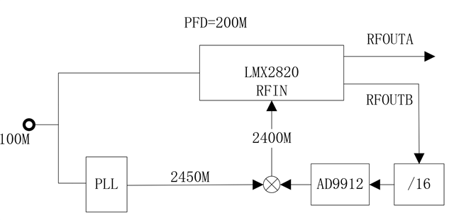
the above is my schematic diagram,i use loopback mode,and the registers configuration is as following,but i can't lock,how to configure the register

mem[0] <= 24'h4F001E ; //R79 [8] OUTB_PD 0:normal 1:pwr down ;[5:4]OUTB_MUX 0 = Channel divider,1=VCO,2=VCO doubler ;[3:1] OUTA_PWR
mem[1] <= 24'h4E0001 ; //R78 [4]OUTA_PD [1-0]OUTA_MUX
mem[2] <= 24'h4D0608 ; //R77 [7] PINMUTE_POL Sets the polarity of mute control for MUTE pin. 0x0 = Active HIG 0x1 = Active LOW
mem[3] <= 24'h46000E ; //R70 [7]DBLBUF_OUTMUX_EN [6]DBLBUF_OUTBUF_EN [5]DBLBUF_CHDIV_EN [4]DBLBUF_PLL_EN
mem[4] <= 24'h440020 ; //R68
mem[5] <= 24'h250300 ; //R37 PFD_DLY
mem[6] <= 24'h24000C ; //R36 [14:0] PLL_N Sets N divider value
mem[7] <= 24'h233000 ; //R35 [8:7] MASH_ORDER 0=Integer mode
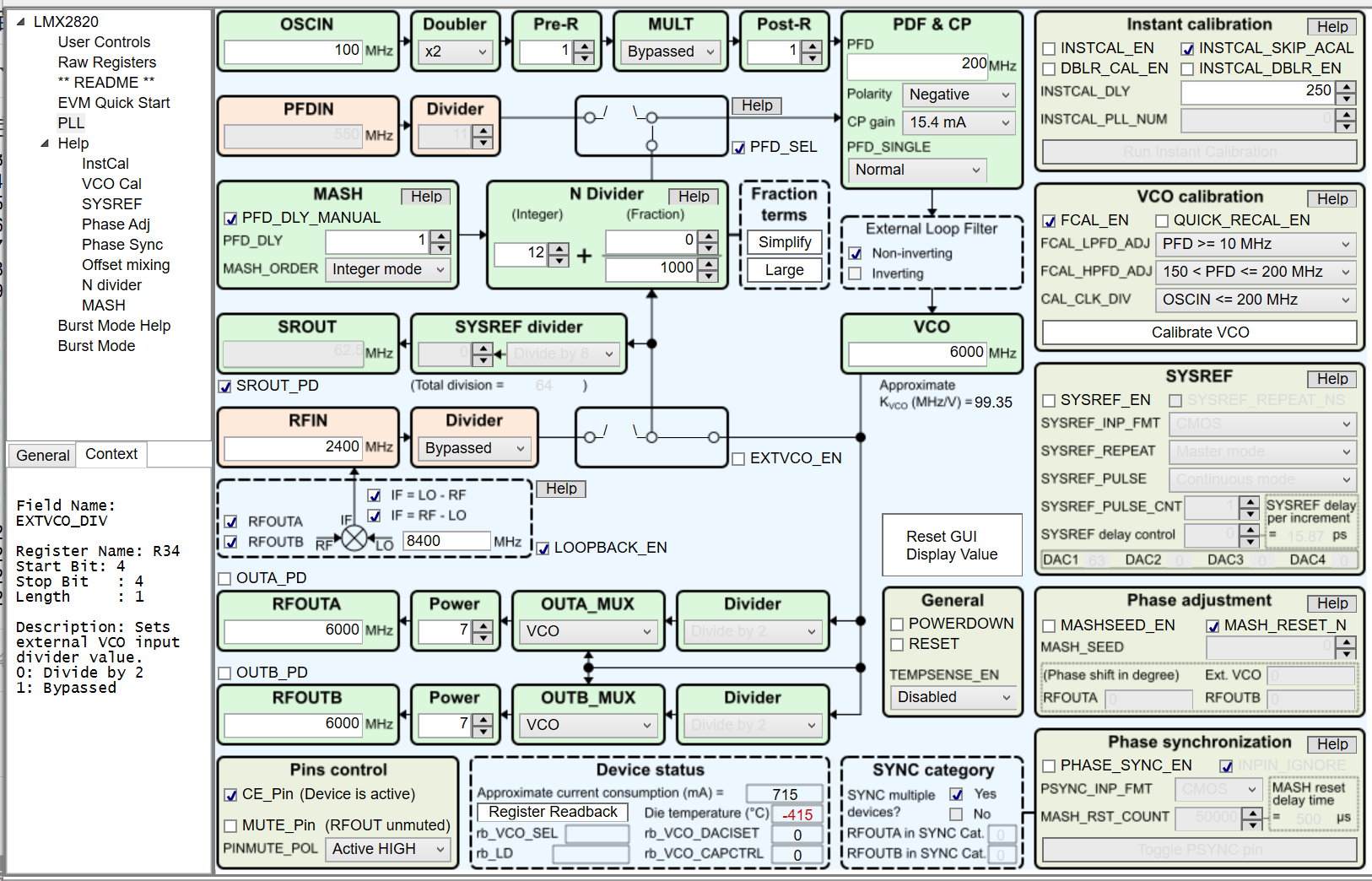
mem[8] <= 24'h220810 ; //R34 LOOPBACK_EN=1 EXTVCO_DIV=1
mem[9] <= 24'h171103 ; //R23 [0] VCO_SEL_FORCE 0x0 = Disable 0x1 = Enabled Forces the VCO to use the core specified by VCO_SEL Useful for full-assisted VCO calibration and debugging purposes.
mem[10] <= 24'h1622BF ; //R22 [15:13]VCO_SEL [7:0]VCO_CAPCTRL VCO1 5.65~6.35G VCO2 6.35~7.3G VCO3 7.3~8.1G
mem[11] <= 24'h120000 ; //R18
mem[12] <= 24'h1115C0 ; //R17
mem[13] <= 24'h10171E ; //R16 [4:1] CPG
mem[14] <= 24'h0F2001 ; //R15 [11] PFD_POL [10:9]PFD_SINGLE 0x0 = Normal operation 0x3 = Single PFD
mem[15] <= 24'h0D0038 ; //R13 [12:5]PLL_R Sets reference path Post-R divider value.
mem[16] <= 24'h0B0612 ; //R11 [4] OSC_2X 0 = Disabled 1=enable
mem[17] <= 24'h0A1000 ; //R10 [12]PFD_DLY_MANUAL
mem[18] <= 24'h070000 ; //R7
mem[19] <= 24'h050032 ; //R5
mem[20] <= 24'h030041 ; //R3
mem[21] <= 24'h0281F4 ; //R2 [14:12]CAL_CLK_DIV [11:1] INSTCAL_DLY [0]QUICK_RECAL_EN
mem[22] <= 24'h0157A0 ; //R1
mem[23] <= 24'h006430 ; //R0
  • 已经收到了您的案例,调查需要些时间,感谢您的耐心等待。

  • Hi,

    Before the loop is locked, RFoutB frequency is not 6GHz, the input frequency to AD9912 is not 375MHz. What is the output frequency of AD9912?

  • Hi,

    Before the loop is locked, RFoutB frequency is not 6GHz, the input frequency to AD9912 is not 375MHz. What is the output frequency of AD9912?

  • if i choose vco1 band 5.65~6.35G, the output frequency i desired is 6.2G,then i set the FTW of AD9912 to (50Mx16/6200M)*2^48, that is if locked to 6400M,the AD9912's output is 6200M/16xFTW/2^48=50M; if not locked,like 5.65G ,then the AD9912's output is 5650M/16xFTW/2^48=45.564516129...M, or 6.35G ,the AD9912's output is 6350M/16xFTW/2^48=51.209677419...M。

    if i choose vco2 band 6.35~7.3G, the output frequency i desired is 6.4G,then i set the FTW of AD9912 to (50Mx16/6400M)*2^48, that is if locked to 6400M,the AD9912's output is 6400M/16xFTW/2^48=50M; if not locked,like 6.35G ,then the AD9912's output is 6350M/16xFTW/2^48=49.609375M, or 7.3G ,the AD9912's output is 7300M/16xFTW/2^48=57.03125M。

    so i need to force the vco band,to limit the AD9912's output within a specific frequency range. then i could choose a proper  saw filter to filter mixer's output ,leave a clean 2400M signal

  • Hi Lian ales,

    OK, so basically the AD9912 is a fixed divider. 

    I guess the reason why LMX2820 does not lock could be due to the mixer is high side injection. That is LO (2450MHz) is higher than RF (50MHz). 

    IF = LO - RF. 

    When RF frequency is smaller, IF is higher. LMX2820 thinks the output frequency is too high, so it tried to reduce the output frequency further. As a result, it is not able to lock.

    Can you change the mixer configuration to low side injection?

  • i changed LO to 2350M,then IF=LO+RF, LO(2350M) ,RF(50M), IF=2400M,but it still did not lock.

    I have used single PFD mode before , the IF=LO+RF, LO(500M) ,RF(50M), IF=550M, and  i sent the 550M to the PFDIN pin, pfd=50M in this mode.with this method,i locked 5800M~8000M,but the phase noise is not well,it is worse than i directly sent the RF(50M) to the PFDIN pin. and the phase noise is only 102dBc/Hz@10K~100K. so i changed to loopback mode,try PFD=200M to improve my phase noise. 

    in PFD mode,everytime i changed frequency more than 50M,i should changed  PLL_N  resigser in the same time ,for example if  i want lock 5900.00000M to 5949.99999M, i set PLL_N=5900/50=118 first,  then  changed the FTW of AD9912 to lock to the frac part . if i want lock 5950.00000M to 5999.99999M, i should set  PLL_N=5950/50=119 first,  then changed the FTW of AD9912  .

    so Is there any other possibility,is the registers  configuration right in the loopback mode?


  • Hi ,

    one question, do they have a filter in IF path?

    I will review the loop back mode operation, see if anything is missing. 

  • yes ,in pfd mode i also use a saw filter ,the center frequency is 550M;  in loopback mode ,i change the filter's  center frequency to 2400M

  • Hi,

    I checked the operation, it is quite straight forward, but there are couples of thing to note:

    1. we should first program the LMX device to lock without enabling the loop back mode. Then enable the loopback_en bit.

    2. RFin pin is sensitive to input signals, if there are multiple input signals, loopback mode operation may be affected. Other unwanted signals going to RFin pin should be smaller than -40dBm. 

    3. we may need to adjust PFD_DLY to make stable lock

    4. Since N-divider changes from 30 to 12 in loopback mode, loop bandwidth and phase margin has changed a lot. Try reducing the charge pump current to increase phase margin for a stable lock

  • 1. we should first program the LMX device to lock without enabling the loop back mode. Then enable the loopback_en bit.

    if i want to change frequency, like 5950.001MHz,but the pfd is 200M,does that mean i should lock to the frac mode first ,without enabling the loop back mode,then enable the loopback_en bit..       if  i  change another frequency, like 7602.001MHz,  i should lock to the frac mode without enabling the loop back mode again ,then enable the loopback_en bit?   if this is right,the lock time is too long

  • Hi,

    No, I think only the initialization requires internal loopback. Let me check.

  • Is there any result

  • Hi ales,

    It is confirmed that VCO calibration works only with internal VCO. In loopback mode, if we want to make a big internal VCO frequency change that require a VCO calibration, we have to exist loopback mode, calibrate the internal VCO, then go back to loopback mode. 

    If the VCO frequency change is small, approx. 80MHz at VCO frequency, we can skip calibration and make the frequency change in loopback mode.

  • thanks Lydia,

    first,i works with internal VCO,the initial registers setting is 

    mem[0] <= 24'h4F001E ; //R79 [8] OUTB_PD 0:normal 1:pwr down ;[5:4]OUTB_MUX 0 = Channel divider,1=VCO,2=VCO doubler ;[3:1] OUTA_PWR
    mem[1] <= 24'h4E0001 ; //R78 [4]OUTA_PD [1-0]OUTA_MUX
    mem[2] <= 24'h4D0608 ; //R77 [7] PINMUTE_POL Sets the polarity of mute control for MUTE pin. 0x0 = Active HIG 0x1 = Active LOW
    mem[3] <= 24'h46000E ; //R70 [7]DBLBUF_OUTMUX_EN [6]DBLBUF_OUTBUF_EN [5]DBLBUF_CHDIV_EN [4]DBLBUF_PLL_EN
    mem[4] <= 24'h440020 ; //R68
    mem[5] <= 24'h250300 ; //R37 PFD_DLY
    mem[6] <= 24'h24003B ; //R36 [14:0] PLL_N Sets N divider value
    mem[7] <= 24'h233000 ; //R35 [8:7] MASH_ORDER 0=Integer mode
    mem[8] <= 24'h220010 ; //R34 LOOPBACK_EN=1 EXTVCO_DIV=1 mem[8] <= 24'h220810
    mem[9] <= 24'h171103 ; //R23 [0] VCO_SEL_FORCE 0x0 = Disable 0x1 = Enabled Forces the VCO to use the core specified by VCO_SEL Useful for full-assisted VCO calibration and debugging purposes.
    mem[10] <= 24'h1622BF ; //R22 [15:13]VCO_SEL [7:0]VCO_CAPCTRL VCO1 5.65~6.35G VCO2 6.35~7.3G VCO3 7.3~8.1G
    mem[11] <= 24'h120000 ; //R18
    mem[12] <= 24'h1115C0 ; //R17
    mem[13] <= 24'h10171E ; //R16 [4:1] CPG
    mem[14] <= 24'h0F2001 ; //R15 [11] PFD_POL [10:9]PFD_SINGLE 0x0 = Normal operation 0x3 = Single PFD
    mem[15] <= 24'h0D0038 ; //R13 [12:5]PLL_R Sets reference path Post-R divider value.
    mem[16] <= 24'h0B0602 ; //R11 [4] OSC_2X 0 = Disabled 1=enable
    mem[17] <= 24'h0A0000 ; //R10 [12]PFD_DLY_MANUAL mem[17] <= 24'h0A1000
    mem[18] <= 24'h070000 ; //R7
    mem[19] <= 24'h050032 ; //R5
    mem[20] <= 24'h030041 ; //R3
    mem[21] <= 24'h0281F4 ; //R2 [14:12]CAL_CLK_DIV [11:1] INSTCAL_DLY [0]QUICK_RECAL_EN
    mem[22] <= 24'h0157A0 ; //R1
    mem[23] <= 24'h006030 ; //R0

    then if frequency changes,i still works with  internal VCO,and lock to Integer multiples of 100M

    if(Freq<24'd5950_000) 
    begin mem[0]<=24'h24003B;mem[1] <= 24'h220010;mem[2]<=24'h1622BF;mem[3]<= 24'h0A0000;mem[4]<=24'h006030;end //VCO1 5.65~6.35G

    else if(Freq>=24'd5950_000&&Freq<=24'd6050_000)
    begin mem[0]<=24'h24003C;mem[1] <= 24'h220010;mem[2]<=24'h1622BF;mem[3]<= 24'h0A0000;mem[4]<=24'h006030;end //VCO1 5.65~6.35G

    .....

    then in the lock state,i changed to loopback mode, and the VCO frequency change is small

     begin mem[0]<=24'h240018;mem[1] <= 24'h220810;mem[2]<= 24'h0A1000;end


    just like ,i changed from 5900M to 5900.999M, but the pll will lost lock

  • Hi,

    The operation is pretty straight forward, 

    1. program the device to lock to the desired VCO frequency

    2. program LOOPBACK_EN=1 to enable loop back mode. If the external LO is high-side injection, program PFD_POL=1 to "positive". That is, VCO frequency is higher with higher Vtune voltage. 

    3. If changing VCO frequency requires a VCO calibration, exit loopback mode, lock the VCO to the desired frequency and then enable loopback mode again.

    Single PFD mode and manual PFD_DLY are not needed, they are required for PFDIN input but not RFIN input.

    I suggest get started with no-assist calibration first. 

  • can u give me a whole register configuration from  normal workmode to LOOPBACK mode,i tried the above methods,but still didn't lock from normal workmode to LOOPBACK mode,

    if(Freq<24'd5950_000)
    begin mem[0]<=24'h24003B;mem[1] <= 24'h220010;mem[2]<=24'h1622BF;mem[3]<= 24'h0A0000;mem[4]<=24'h006030;end //VCO1 5.65~6.35G

    ......

      begin mem[0]<=24'h240018;mem[1] <= 24'h220810;mem[2]<= 24'h0A1000;end,

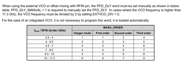
    and in the fig,  manual PFD_DLY are needed,when using  offset mixing with  RFIN pin

  • sorry,i had mad a big mistake, when working in the normal mode,in the lock state,i changed to loopback mode, i worte register 0x240018,so it lost lock.now i delete the the register 0x240018,  just only write 0x220810, it still locks,but  the frequency did not change , i read the register 0x22,it shows  the state had changed from normal mode to loopback mode.why the frequency did not change?

  • If the cause of the issue "LMX2820 LOOPBACK mode does not lock" has been identified and resolved, we recommend that you post a new thread for any other issues.