SN65DSI83: SN65DSI83 驱动支持问题

Part Number: SN65DSI83
Other Parts Discussed in Thread: SN65DSI84, SN65DSI85

非常感谢支持,如下是问题和背景(第3点)详细描述

1、验证目标:

希望通过IMX8MM 初始化SN65DSI83后实现其DSI to LVDS 的功能来点亮屏幕,主要是验证转接功能,即便是屏幕不亮,如果可以验证SN65DSI83转接功能正常也可以达到验证目标。

2、问题描述

问题1: SN65DSI83 驱动报错如下log,尝试修改过lcd参数,没有任何效果,即便是屏幕不亮,有没有debug验证方法来验证 SN65DSI83转接功能是正常的?比如读写SN65DSI83哪个寄存器?或者测量哪些信号

root@imx8mm-lpddr4-evk:~# dmesg | grep -Ei "Debug|mipi|i2c|drm|sdi|sn65|failed"
[    0.098335] platform 32e00000.lcdif: Fixed dependency cycle(s) with /soc@0/bus@32c00000/mipi_dsi@32e10000
[    0.098559] platform 32e00000.lcdif: Fixed dependency cycle(s) with /soc@0/bus@32c00000/mipi_dsi@32e10000
[    0.098674] platform 32e10000.mipi_dsi: Fixed dependency cycle(s) with /soc@0/bus@30800000/i2c@30a40000/sn65dsi83@2c
[    0.098702] platform 32e10000.mipi_dsi: Fixed dependency cycle(s) with /soc@0/bus@32c00000/lcdif@32e00000
[    0.099310] platform 32e40000.usb: Fixed dependency cycle(s) with /soc@0/bus@30800000/i2c@30a30000/tcpc@50/connector
[    0.103172] platform panel@0: Fixed dependency cycle(s) with /soc@0/bus@30800000/i2c@30a40000/sn65dsi83@2c
[    0.246847] imx-drm display-subsystem: bound imx-lcdif-crtc.0 (ops lcdif_crtc_ops)
[    0.279313] i2c_dev: i2c /dev entries driver
[    0.363694] i2c i2c-0: using DT '/soc@0/bus@30800000/i2c@30a20000' for 'scl' GPIO lookup
[    0.363717] of_get_named_gpiod_flags: can't parse 'scl-gpios' property of node '/soc@0/bus@30800000/i2c@30a20000[0]'
[    0.363740] of_get_named_gpiod_flags: can't parse 'scl-gpio' property of node '/soc@0/bus@30800000/i2c@30a20000[0]'
[    0.363757] i2c i2c-0: using lookup tables for GPIO lookup
[    0.363764] i2c i2c-0: No GPIO consumer scl found
[    0.363783] i2c i2c-0: using DT '/soc@0/bus@30800000/i2c@30a20000' for 'sda' GPIO lookup
[    0.363804] of_get_named_gpiod_flags: can't parse 'sda-gpios' property of node '/soc@0/bus@30800000/i2c@30a20000[0]'
[    0.363825] of_get_named_gpiod_flags: can't parse 'sda-gpio' property of node '/soc@0/bus@30800000/i2c@30a20000[0]'
[    0.363841] i2c i2c-0: using lookup tables for GPIO lookup
[    0.363848] i2c i2c-0: No GPIO consumer sda found
[    0.364245] i2c i2c-0: IMX I2C adapter registered
[    0.365239] i2c i2c-1: using DT '/soc@0/bus@30800000/i2c@30a30000' for 'scl' GPIO lookup
[    0.365274] of_get_named_gpiod_flags: can't parse 'scl-gpios' property of node '/soc@0/bus@30800000/i2c@30a30000[0]'
[    0.365298] of_get_named_gpiod_flags: can't parse 'scl-gpio' property of node '/soc@0/bus@30800000/i2c@30a30000[0]'
[    0.365317] i2c i2c-1: using lookup tables for GPIO lookup
[    0.365324] i2c i2c-1: No GPIO consumer scl found
[    0.365342] i2c i2c-1: using DT '/soc@0/bus@30800000/i2c@30a30000' for 'sda' GPIO lookup
[    0.365363] of_get_named_gpiod_flags: can't parse 'sda-gpios' property of node '/soc@0/bus@30800000/i2c@30a30000[0]'
[    0.365383] of_get_named_gpiod_flags: can't parse 'sda-gpio' property of node '/soc@0/bus@30800000/i2c@30a30000[0]'
[    0.365397] i2c i2c-1: using lookup tables for GPIO lookup
[    0.365403] i2c i2c-1: No GPIO consumer sda found
[    0.368364] i2c i2c-1: IMX I2C adapter registered
[    0.369351] i2c i2c-2: using DT '/soc@0/bus@30800000/i2c@30a40000' for 'scl' GPIO lookup
[    0.369385] of_get_named_gpiod_flags: can't parse 'scl-gpios' property of node '/soc@0/bus@30800000/i2c@30a40000[0]'
[    0.369406] of_get_named_gpiod_flags: can't parse 'scl-gpio' property of node '/soc@0/bus@30800000/i2c@30a40000[0]'
[    0.369421] i2c i2c-2: using lookup tables for GPIO lookup
[    0.369428] i2c i2c-2: No GPIO consumer scl found
[    0.369447] i2c i2c-2: using DT '/soc@0/bus@30800000/i2c@30a40000' for 'sda' GPIO lookup
[    0.369467] of_get_named_gpiod_flags: can't parse 'sda-gpios' property of node '/soc@0/bus@30800000/i2c@30a40000[0]'
[    0.369489] of_get_named_gpiod_flags: can't parse 'sda-gpio' property of node '/soc@0/bus@30800000/i2c@30a40000[0]'
[    0.369507] i2c i2c-2: using lookup tables for GPIO lookup
[    0.369515] i2c i2c-2: No GPIO consumer sda found
[    0.369830] platform panel@0: Fixed dependency cycle(s) with /soc@0/bus@30800000/i2c@30a40000/sn65dsi83@2c
[    0.369954] i2c 2-002c: Fixed dependency cycle(s) with /panel@0
[    0.370259] sn65dsi83 2-002c: Debug: DT matched - compatible=ti,sn65dsi83, model=0
[    0.370270] sn65dsi83 2-002c: using DT '/soc@0/bus@30800000/i2c@30a40000/sn65dsi83@2c' for 'enable' GPIO lookup
[    0.370309] of_get_named_gpiod_flags: parsed 'enable-gpios' property of node '/soc@0/bus@30800000/i2c@30a40000/sn65dsi83@2c[0]' - status (0)
[    0.370357] sn65dsi83 2-002c: Debug: Enable GPIO acquired successfully
[    0.377976] nxp-pca9450 0-0025: using DT '/soc@0/bus@30800000/i2c@30a20000/pca9450@25' for 'sd-vsel' GPIO lookup
[    0.378009] of_get_named_gpiod_flags: can't parse 'sd-vsel-gpios' property of node '/soc@0/bus@30800000/i2c@30a20000/pca9450@25[0]'
[    0.378036] of_get_named_gpiod_flags: can't parse 'sd-vsel-gpio' property of node '/soc@0/bus@30800000/i2c@30a20000/pca9450@25[0]'
[    0.381381] sn65dsi83 2-002c: Debug: Parsing device tree for model 0
[    0.381408] sn65dsi83 2-002c: Debug: Panel bridge (port 2) not ready, deferring probe (ret=-517)
[    0.381416] sn65dsi83 2-002c: Debug: Failed to parse device tree, ret=-517
[    0.388532] i2c i2c-2: IMX I2C adapter registered
[    0.389586] i2c i2c-3: using DT '/soc@0/bus@30800000/i2c@30a50000' for 'scl' GPIO lookup
[    0.389615] of_get_named_gpiod_flags: can't parse 'scl-gpios' property of node '/soc@0/bus@30800000/i2c@30a50000[0]'
[    0.389635] of_get_named_gpiod_flags: can't parse 'scl-gpio' property of node '/soc@0/bus@30800000/i2c@30a50000[0]'
[    0.389651] i2c i2c-3: using lookup tables for GPIO lookup
[    0.389657] i2c i2c-3: No GPIO consumer scl found
[    0.389675] i2c i2c-3: using DT '/soc@0/bus@30800000/i2c@30a50000' for 'sda' GPIO lookup
[    0.389693] of_get_named_gpiod_flags: can't parse 'sda-gpios' property of node '/soc@0/bus@30800000/i2c@30a50000[0]'
[    0.389711] of_get_named_gpiod_flags: can't parse 'sda-gpio' property of node '/soc@0/bus@30800000/i2c@30a50000[0]'
[    0.389725] i2c i2c-3: using lookup tables for GPIO lookup
[    0.389731] i2c i2c-3: No GPIO consumer sda found
[    0.390166] i2c i2c-3: IMX I2C adapter registered
[    0.394183] imx-drm display-subsystem: bound imx-lcdif-crtc.0 (ops lcdif_crtc_ops)
[    0.518539] galcore: clk_get vg clock failed, disable vg!
[    0.560767] [drm] Initialized vivante 1.0.0 for 38000000.gpu on minor 0
[    0.571441] sn65dsi83 2-002c: Debug: DT matched - compatible=ti,sn65dsi83, model=0
[    0.571463] sn65dsi83 2-002c: using DT '/soc@0/bus@30800000/i2c@30a40000/sn65dsi83@2c' for 'enable' GPIO lookup
[    0.571496] of_get_named_gpiod_flags: parsed 'enable-gpios' property of node '/soc@0/bus@30800000/i2c@30a40000/sn65dsi83@2c[0]' - status (0)
[    0.571537] sn65dsi83 2-002c: Debug: Enable GPIO acquired successfully
[    0.582560] sn65dsi83 2-002c: Debug: Parsing device tree for model 0
[    0.582593] sn65dsi83 2-002c: Debug: Panel bridge (port 2) not ready, deferring probe (ret=-517)
[    0.582603] sn65dsi83 2-002c: Debug: Failed to parse device tree, ret=-517
[    0.592182] imx-drm display-subsystem: bound imx-lcdif-crtc.0 (ops lcdif_crtc_ops)
[    0.593326] sn65dsi83 2-002c: Debug: DT matched - compatible=ti,sn65dsi83, model=0
[    0.593349] sn65dsi83 2-002c: using DT '/soc@0/bus@30800000/i2c@30a40000/sn65dsi83@2c' for 'enable' GPIO lookup
[    0.593393] of_get_named_gpiod_flags: parsed 'enable-gpios' property of node '/soc@0/bus@30800000/i2c@30a40000/sn65dsi83@2c[0]' - status (0)
[    0.593443] sn65dsi83 2-002c: Debug: Enable GPIO acquired successfully
[    0.604319] sn65dsi83 2-002c: Debug: Parsing device tree for model 0
[    0.604347] sn65dsi83 2-002c: Debug: Panel bridge (port 2) not ready, deferring probe (ret=-517)
[    0.604355] sn65dsi83 2-002c: Debug: Failed to parse device tree, ret=-517
[    0.610644] mmc0: new ultra high speed SDR104 SDIO card at address 0001
[    0.613636] imx-drm display-subsystem: bound imx-lcdif-crtc.0 (ops lcdif_crtc_ops)
[    1.647980] systemd[1]: Mounting Kernel Debug File System...
[    1.719821] systemd[1]: Starting Load Kernel Module drm...
[    1.885080] systemd[1]: Mounted Kernel Debug File System.
[    1.933444] systemd[1]: modprobe@drm.service: Deactivated successfully.
[    1.934051] systemd[1]: Finished Load Kernel Module drm.
[   10.725256] sn65dsi83 2-002c: Debug: DT matched - compatible=ti,sn65dsi83, model=0
[   10.725282] sn65dsi83 2-002c: using DT '/soc@0/bus@30800000/i2c@30a40000/sn65dsi83@2c' for 'enable' GPIO lookup
[   10.725327] of_get_named_gpiod_flags: parsed 'enable-gpios' property of node '/soc@0/bus@30800000/i2c@30a40000/sn65dsi83@2c[0]' - status (0)
[   10.725380] sn65dsi83 2-002c: Debug: Enable GPIO acquired successfully
[   10.736713] sn65dsi83 2-002c: Debug: Parsing device tree for model 0
[   10.736755] sn65dsi83 2-002c: Debug: Panel bridge (port 2) not ready, deferring probe (ret=-517)
[   10.736764] sn65dsi83 2-002c: Debug: Failed to parse device tree, ret=-517
[   10.748066] imx-drm display-subsystem: bound imx-lcdif-crtc.0 (ops lcdif_crtc_ops)
[   10.748967] i2c 2-002c: deferred probe pending: (reason unknown)
root@imx8mm-lpddr4-evk:~# i2cdetect -l
i2c-0   i2c             30a20000.i2c                            I2C adapter
i2c-1   i2c             30a30000.i2c                            I2C adapter
i2c-2   i2c             30a40000.i2c                            I2C adapter
i2c-3   i2c             30a50000.i2c                            I2C adapter
root@imx8mm-lpddr4-evk:~# i2cdetect -y 2
     0  1  2  3  4  5  6  7  8  9  a  b  c  d  e  f
00:                         -- -- -- -- -- -- -- --
10: -- -- -- -- -- -- -- -- -- -- -- -- -- -- -- --
20: 20 -- -- -- -- -- -- -- -- -- -- -- 2c -- -- --
30: -- -- -- -- -- -- -- -- -- -- -- -- -- -- -- --
40: -- -- -- -- -- -- -- -- -- -- -- -- -- -- -- --
50: -- -- -- -- -- -- -- -- -- -- -- -- -- -- -- --
60: -- -- -- -- -- -- -- -- -- -- -- -- -- -- -- --
70: -- -- -- -- -- -- -- --
root@imx8mm-lpddr4-evk:~#
 

问题2 有没有原厂屏幕的购买信息?

想要购买SN65DSI83 转接板的lcd屏幕来验证(排除lcd 屏的差异), 能否提供购买方法?


问题3   后续量产硬件连接 ,SN65DSI83 外接的不是屏幕是FPGA 的lvds 接口


SN65DSI83 现有驱动是否支持这种FPGA的连接方式?


3、如下是软硬件环境信息

3.1 硬件环境:

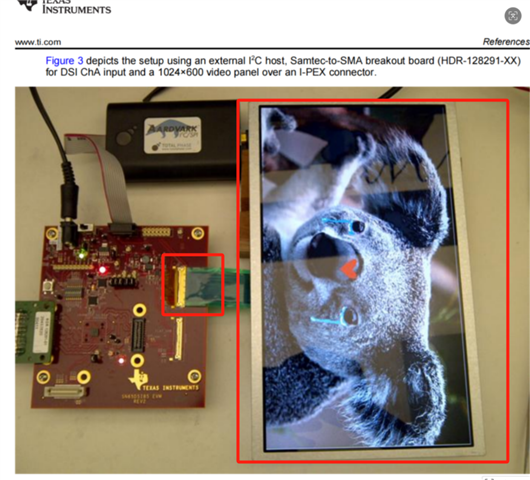
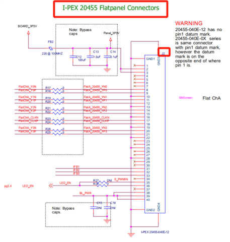
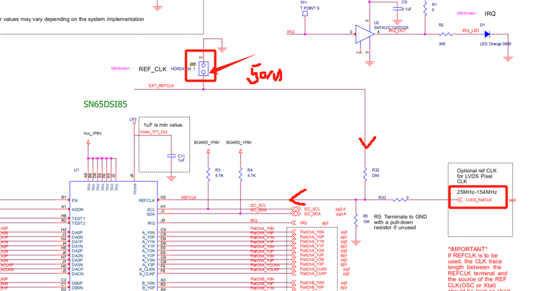
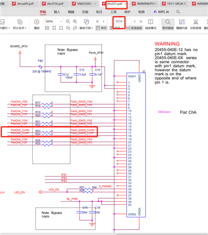
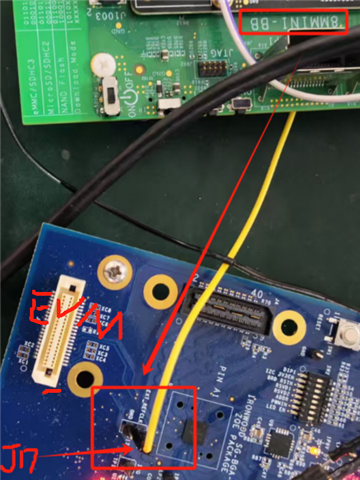
IMX8MM 开发板 MIPI DSI output 接 电平转换后再接TiSN65DSI83官方实验板再飞线接BOE

Imx8侧确认硬件没有问题,换个DSI转HDMI的转接板接显示器可以出图,BOE屏单独测试可以点亮 ,如下连接设置驱动报错

环境连接拓扑如下

 2474b368-d340-47af-88cd-08fd5f475aeb.png

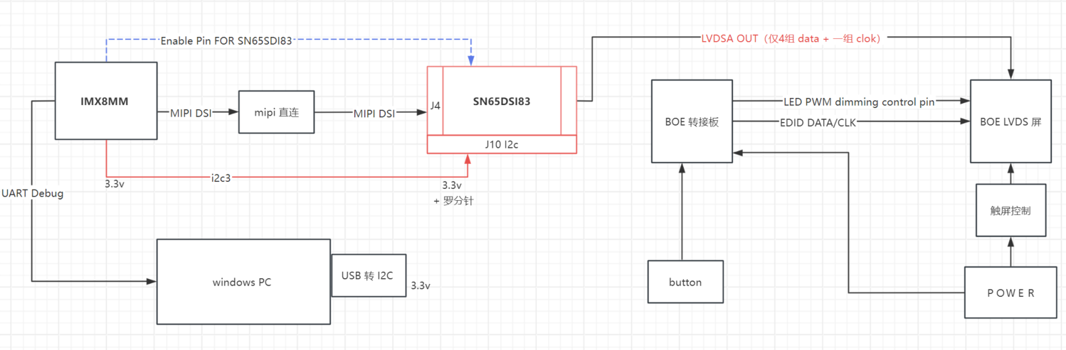
没有找到和SN65DSI83 对应的原厂屏幕,所以采用的飞线的方式接BOE的屏进行测试


3.2、软件环境

NXP yocto 编译,LINUX 内核版本6.12
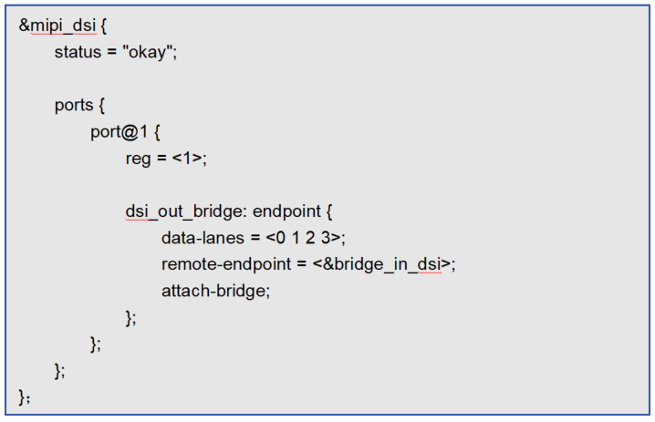
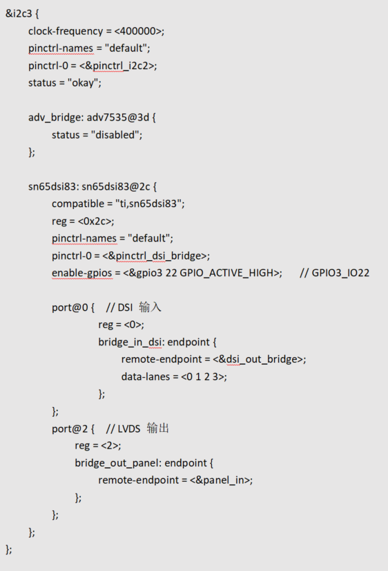
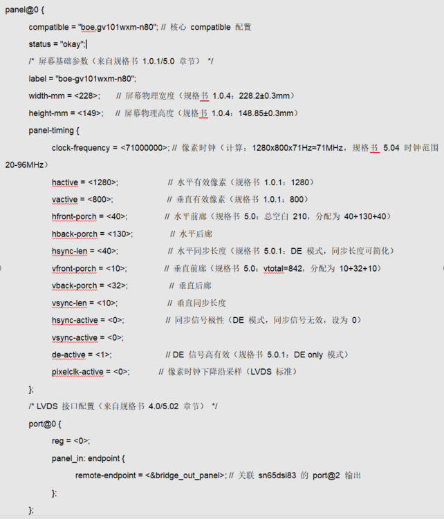
设备树配置如下

image.png


image.png

image.png

  • 已经收到了您的案例,调查需要些时间,感谢您的耐心等待。

  • 非常感谢支持:

    问题1 补充:使用的驱动代码文件是kernel-source\drivers\gpu\drm\bridge\ti-sn65dsi83.c    linux 内核版本6.12, 在源代码基础上仅仅加了些debug打印,654行会出问题1 的log

    // SPDX-License-Identifier: GPL-2.0
    /*
     * TI SN65DSI83,84,85 driver
     *
     * Currently supported:
     * - SN65DSI83
     *   = 1x Single-link DSI ~ 1x Single-link LVDS
     *   - Supported
     *   - Single-link LVDS mode tested
     * - SN65DSI84
     *   = 1x Single-link DSI ~ 2x Single-link or 1x Dual-link LVDS
     *   - Supported
     *   - Dual-link LVDS mode tested
     *   - 2x Single-link LVDS mode unsupported
     *     (should be easy to add by someone who has the HW)
     * - SN65DSI85
     *   = 2x Single-link or 1x Dual-link DSI ~ 2x Single-link or 1x Dual-link LVDS
     *   - Unsupported
     *     (should be easy to add by someone who has the HW)
     *
     * Copyright (C) 2021 Marek Vasut <marex@denx.de>
     *
     * Based on previous work of:
     * Valentin Raevsky <valentin@compulab.co.il>
     * Philippe Schenker <philippe.schenker@toradex.com>
     */
    
    #include <linux/bits.h>
    #include <linux/clk.h>
    #include <linux/gpio/consumer.h>
    #include <linux/i2c.h>
    #include <linux/media-bus-format.h>
    #include <linux/module.h>
    #include <linux/of.h>
    #include <linux/of_graph.h>
    #include <linux/of_device.h>  // Added for of_match_device()
    #include <linux/regmap.h>
    #include <linux/regulator/consumer.h>
    
    #include <drm/drm_atomic_helper.h>
    #include <drm/drm_bridge.h>
    #include <drm/drm_mipi_dsi.h>
    #include <drm/drm_of.h>
    #include <drm/drm_panel.h>
    #include <drm/drm_print.h>
    #include <drm/drm_probe_helper.h>
    
    /* ID registers */
    #define REG_ID(n)				(0x00 + (n))
    /* Reset and clock registers */
    #define REG_RC_RESET				0x09
    #define  REG_RC_RESET_SOFT_RESET		BIT(0)
    #define REG_RC_LVDS_PLL				0x0a
    #define  REG_RC_LVDS_PLL_PLL_EN_STAT		BIT(7)
    #define  REG_RC_LVDS_PLL_LVDS_CLK_RANGE(n)	(((n) & 0x7) << 1)
    #define  REG_RC_LVDS_PLL_HS_CLK_SRC_DPHY	BIT(0)
    #define REG_RC_DSI_CLK				0x0b
    #define  REG_RC_DSI_CLK_DSI_CLK_DIVIDER(n)	(((n) & 0x1f) << 3)
    #define  REG_RC_DSI_CLK_REFCLK_MULTIPLIER(n)	((n) & 0x3)
    #define REG_RC_PLL_EN				0x0d
    #define  REG_RC_PLL_EN_PLL_EN			BIT(0)
    /* DSI registers */
    #define REG_DSI_LANE				0x10
    #define  REG_DSI_LANE_LEFT_RIGHT_PIXELS		BIT(7)	/* DSI85-only */
    #define  REG_DSI_LANE_DSI_CHANNEL_MODE_DUAL	0	/* DSI85-only */
    #define  REG_DSI_LANE_DSI_CHANNEL_MODE_2SINGLE	BIT(6)	/* DSI85-only */
    #define  REG_DSI_LANE_DSI_CHANNEL_MODE_SINGLE	BIT(5)
    #define  REG_DSI_LANE_CHA_DSI_LANES(n)		(((n) & 0x3) << 3)
    #define  REG_DSI_LANE_CHB_DSI_LANES(n)		(((n) & 0x3) << 1)
    #define  REG_DSI_LANE_SOT_ERR_TOL_DIS		BIT(0)
    #define REG_DSI_EQ				0x11
    #define  REG_DSI_EQ_CHA_DSI_DATA_EQ(n)		(((n) & 0x3) << 6)
    #define  REG_DSI_EQ_CHA_DSI_CLK_EQ(n)		(((n) & 0x3) << 2)
    #define REG_DSI_CLK				0x12
    #define  REG_DSI_CLK_CHA_DSI_CLK_RANGE(n)	((n) & 0xff)
    /* LVDS registers */
    #define REG_LVDS_FMT				0x18
    #define  REG_LVDS_FMT_DE_NEG_POLARITY		BIT(7)
    #define  REG_LVDS_FMT_HS_NEG_POLARITY		BIT(6)
    #define  REG_LVDS_FMT_VS_NEG_POLARITY		BIT(5)
    #define  REG_LVDS_FMT_LVDS_LINK_CFG		BIT(4)	/* 0:AB 1:A-only */
    #define  REG_LVDS_FMT_CHA_24BPP_MODE		BIT(3)
    #define  REG_LVDS_FMT_CHB_24BPP_MODE		BIT(2)
    #define  REG_LVDS_FMT_CHA_24BPP_FORMAT1		BIT(1)
    #define  REG_LVDS_FMT_CHB_24BPP_FORMAT1		BIT(0)
    #define REG_LVDS_VCOM				0x19
    #define  REG_LVDS_VCOM_CHA_LVDS_VOCM		BIT(6)
    #define  REG_LVDS_VCOM_CHB_LVDS_VOCM		BIT(4)
    #define  REG_LVDS_VCOM_CHA_LVDS_VOD_SWING(n)	(((n) & 0x3) << 2)
    #define  REG_LVDS_VCOM_CHB_LVDS_VOD_SWING(n)	((n) & 0x3)
    #define REG_LVDS_LANE				0x1a
    #define  REG_LVDS_LANE_EVEN_ODD_SWAP		BIT(6)
    #define  REG_LVDS_LANE_CHA_REVERSE_LVDS		BIT(5)
    #define  REG_LVDS_LANE_CHB_REVERSE_LVDS		BIT(4)
    #define  REG_LVDS_LANE_CHA_LVDS_TERM		BIT(1)
    #define  REG_LVDS_LANE_CHB_LVDS_TERM		BIT(0)
    #define REG_LVDS_CM				0x1b
    #define  REG_LVDS_CM_CHA_LVDS_CM_ADJUST(n)	(((n) & 0x3) << 4)
    #define  REG_LVDS_CM_CHB_LVDS_CM_ADJUST(n)	((n) & 0x3)
    /* Video registers */
    #define REG_VID_CHA_ACTIVE_LINE_LENGTH_LOW	0x20
    #define REG_VID_CHA_ACTIVE_LINE_LENGTH_HIGH	0x21
    #define REG_VID_CHA_VERTICAL_DISPLAY_SIZE_LOW	0x24
    #define REG_VID_CHA_VERTICAL_DISPLAY_SIZE_HIGH	0x25
    #define REG_VID_CHA_SYNC_DELAY_LOW		0x28
    #define REG_VID_CHA_SYNC_DELAY_HIGH		0x29
    #define REG_VID_CHA_HSYNC_PULSE_WIDTH_LOW	0x2c
    #define REG_VID_CHA_HSYNC_PULSE_WIDTH_HIGH	0x2d
    #define REG_VID_CHA_VSYNC_PULSE_WIDTH_LOW	0x30
    #define REG_VID_CHA_VSYNC_PULSE_WIDTH_HIGH	0x31
    #define REG_VID_CHA_HORIZONTAL_BACK_PORCH	0x34
    #define REG_VID_CHA_VERTICAL_BACK_PORCH		0x36
    #define REG_VID_CHA_HORIZONTAL_FRONT_PORCH	0x38
    #define REG_VID_CHA_VERTICAL_FRONT_PORCH	0x3a
    #define REG_VID_CHA_TEST_PATTERN		0x3c
    /* IRQ registers */
    #define REG_IRQ_GLOBAL				0xe0
    #define  REG_IRQ_GLOBAL_IRQ_EN			BIT(0)
    #define REG_IRQ_EN				0xe1
    #define  REG_IRQ_EN_CHA_SYNCH_ERR_EN		BIT(7)
    #define  REG_IRQ_EN_CHA_CRC_ERR_EN		BIT(6)
    #define  REG_IRQ_EN_CHA_UNC_ECC_ERR_EN		BIT(5)
    #define  REG_IRQ_EN_CHA_COR_ECC_ERR_EN		BIT(4)
    #define  REG_IRQ_EN_CHA_LLP_ERR_EN		BIT(3)
    #define  REG_IRQ_EN_CHA_SOT_BIT_ERR_EN		BIT(2)
    #define  REG_IRQ_EN_CHA_PLL_UNLOCK_EN		BIT(0)
    #define REG_IRQ_STAT				0xe5
    #define  REG_IRQ_STAT_CHA_SYNCH_ERR		BIT(7)
    #define  REG_IRQ_STAT_CHA_CRC_ERR		BIT(6)
    #define  REG_IRQ_STAT_CHA_UNC_ECC_ERR		BIT(5)
    #define  REG_IRQ_STAT_CHA_COR_ECC_ERR		BIT(4)
    #define  REG_IRQ_STAT_CHA_LLP_ERR		BIT(3)
    #define  REG_IRQ_STAT_CHA_SOT_BIT_ERR		BIT(2)
    #define  REG_IRQ_STAT_CHA_PLL_UNLOCK		BIT(0)
    
    enum sn65dsi83_model {
    	MODEL_SN65DSI83,
    	MODEL_SN65DSI84,
    };
    
    struct sn65dsi83 {
    	struct drm_bridge		bridge;
    	struct device			*dev;
    	struct regmap			*regmap;
    	struct mipi_dsi_device		*dsi;
    	struct drm_bridge		*panel_bridge;
    	struct gpio_desc		*enable_gpio;
    	struct regulator		*vcc;
    	bool				lvds_dual_link;
    	bool				lvds_dual_link_even_odd_swap;
    };
    
    static const struct regmap_range sn65dsi83_readable_ranges[] = {
    	regmap_reg_range(REG_ID(0), REG_ID(8)),
    	regmap_reg_range(REG_RC_LVDS_PLL, REG_RC_DSI_CLK),
    	regmap_reg_range(REG_RC_PLL_EN, REG_RC_PLL_EN),
    	regmap_reg_range(REG_DSI_LANE, REG_DSI_CLK),
    	regmap_reg_range(REG_LVDS_FMT, REG_LVDS_CM),
    	regmap_reg_range(REG_VID_CHA_ACTIVE_LINE_LENGTH_LOW,
    			 REG_VID_CHA_ACTIVE_LINE_LENGTH_HIGH),
    	regmap_reg_range(REG_VID_CHA_VERTICAL_DISPLAY_SIZE_LOW,
    			 REG_VID_CHA_VERTICAL_DISPLAY_SIZE_HIGH),
    	regmap_reg_range(REG_VID_CHA_SYNC_DELAY_LOW,
    			 REG_VID_CHA_SYNC_DELAY_HIGH),
    	regmap_reg_range(REG_VID_CHA_HSYNC_PULSE_WIDTH_LOW,
    			 REG_VID_CHA_HSYNC_PULSE_WIDTH_HIGH),
    	regmap_reg_range(REG_VID_CHA_VSYNC_PULSE_WIDTH_LOW,
    			 REG_VID_CHA_VSYNC_PULSE_WIDTH_HIGH),
    	regmap_reg_range(REG_VID_CHA_HORIZONTAL_BACK_PORCH,
    			 REG_VID_CHA_HORIZONTAL_BACK_PORCH),
    	regmap_reg_range(REG_VID_CHA_VERTICAL_BACK_PORCH,
    			 REG_VID_CHA_VERTICAL_BACK_PORCH),
    	regmap_reg_range(REG_VID_CHA_HORIZONTAL_FRONT_PORCH,
    			 REG_VID_CHA_HORIZONTAL_FRONT_PORCH),
    	regmap_reg_range(REG_VID_CHA_VERTICAL_FRONT_PORCH,
    			 REG_VID_CHA_VERTICAL_FRONT_PORCH),
    	regmap_reg_range(REG_VID_CHA_TEST_PATTERN, REG_VID_CHA_TEST_PATTERN),
    	regmap_reg_range(REG_IRQ_GLOBAL, REG_IRQ_EN),
    	regmap_reg_range(REG_IRQ_STAT, REG_IRQ_STAT),
    };
    
    static const struct regmap_access_table sn65dsi83_readable_table = {
    	.yes_ranges = sn65dsi83_readable_ranges,
    	.n_yes_ranges = ARRAY_SIZE(sn65dsi83_readable_ranges),
    };
    
    static const struct regmap_range sn65dsi83_writeable_ranges[] = {
    	regmap_reg_range(REG_RC_RESET, REG_RC_DSI_CLK),
    	regmap_reg_range(REG_RC_PLL_EN, REG_RC_PLL_EN),
    	regmap_reg_range(REG_DSI_LANE, REG_DSI_CLK),
    	regmap_reg_range(REG_LVDS_FMT, REG_LVDS_CM),
    	regmap_reg_range(REG_VID_CHA_ACTIVE_LINE_LENGTH_LOW,
    			 REG_VID_CHA_ACTIVE_LINE_LENGTH_HIGH),
    	regmap_reg_range(REG_VID_CHA_VERTICAL_DISPLAY_SIZE_LOW,
    			 REG_VID_CHA_VERTICAL_DISPLAY_SIZE_HIGH),
    	regmap_reg_range(REG_VID_CHA_SYNC_DELAY_LOW,
    			 REG_VID_CHA_SYNC_DELAY_HIGH),
    	regmap_reg_range(REG_VID_CHA_HSYNC_PULSE_WIDTH_LOW,
    			 REG_VID_CHA_HSYNC_PULSE_WIDTH_HIGH),
    	regmap_reg_range(REG_VID_CHA_VSYNC_PULSE_WIDTH_LOW,
    			 REG_VID_CHA_VSYNC_PULSE_WIDTH_HIGH),
    	regmap_reg_range(REG_VID_CHA_HORIZONTAL_BACK_PORCH,
    			 REG_VID_CHA_HORIZONTAL_BACK_PORCH),
    	regmap_reg_range(REG_VID_CHA_VERTICAL_BACK_PORCH,
    			 REG_VID_CHA_VERTICAL_BACK_PORCH),
    	regmap_reg_range(REG_VID_CHA_HORIZONTAL_FRONT_PORCH,
    			 REG_VID_CHA_HORIZONTAL_FRONT_PORCH),
    	regmap_reg_range(REG_VID_CHA_VERTICAL_FRONT_PORCH,
    			 REG_VID_CHA_VERTICAL_FRONT_PORCH),
    	regmap_reg_range(REG_VID_CHA_TEST_PATTERN, REG_VID_CHA_TEST_PATTERN),
    	regmap_reg_range(REG_IRQ_GLOBAL, REG_IRQ_EN),
    	regmap_reg_range(REG_IRQ_STAT, REG_IRQ_STAT),
    };
    
    static const struct regmap_access_table sn65dsi83_writeable_table = {
    	.yes_ranges = sn65dsi83_writeable_ranges,
    	.n_yes_ranges = ARRAY_SIZE(sn65dsi83_writeable_ranges),
    };
    
    static const struct regmap_range sn65dsi83_volatile_ranges[] = {
    	regmap_reg_range(REG_RC_RESET, REG_RC_RESET),
    	regmap_reg_range(REG_RC_LVDS_PLL, REG_RC_LVDS_PLL),
    	regmap_reg_range(REG_IRQ_STAT, REG_IRQ_STAT),
    };
    
    static const struct regmap_access_table sn65dsi83_volatile_table = {
    	.yes_ranges = sn65dsi83_volatile_ranges,
    	.n_yes_ranges = ARRAY_SIZE(sn65dsi83_volatile_ranges),
    };
    
    static const struct regmap_config sn65dsi83_regmap_config = {
    	.reg_bits = 8,
    	.val_bits = 8,
    	.rd_table = &sn65dsi83_readable_table,
    	.wr_table = &sn65dsi83_writeable_table,
    	.volatile_table = &sn65dsi83_volatile_table,
    	.cache_type = REGCACHE_MAPLE,
    	.max_register = REG_IRQ_STAT,
    };
    
    static struct sn65dsi83 *bridge_to_sn65dsi83(struct drm_bridge *bridge)
    {
    	return container_of(bridge, struct sn65dsi83, bridge);
    }
    
    static int sn65dsi83_attach(struct drm_bridge *bridge,
    			    enum drm_bridge_attach_flags flags)
    {
    	struct sn65dsi83 *ctx = bridge_to_sn65dsi83(bridge);
    
    	return drm_bridge_attach(bridge->encoder, ctx->panel_bridge,
    				 &ctx->bridge, flags);
    }
    
    static void sn65dsi83_detach(struct drm_bridge *bridge)
    {
    	struct sn65dsi83 *ctx = bridge_to_sn65dsi83(bridge);
    
    	if (!ctx->dsi)
    		return;
    
    	ctx->dsi = NULL;
    }
    
    static u8 sn65dsi83_get_lvds_range(struct sn65dsi83 *ctx,
    				   const struct drm_display_mode *mode)
    {
    	/*
    	 * The encoding of the LVDS_CLK_RANGE is as follows:
    	 * 000 - 25 MHz <= LVDS_CLK < 37.5 MHz
    	 * 001 - 37.5 MHz <= LVDS_CLK < 62.5 MHz
    	 * 010 - 62.5 MHz <= LVDS_CLK < 87.5 MHz
    	 * 011 - 87.5 MHz <= LVDS_CLK < 112.5 MHz
    	 * 100 - 112.5 MHz <= LVDS_CLK < 137.5 MHz
    	 * 101 - 137.5 MHz <= LVDS_CLK <= 154 MHz
    	 * which is a range of 12.5MHz..162.5MHz in 50MHz steps, except that
    	 * the ends of the ranges are clamped to the supported range. Since
    	 * sn65dsi83_mode_valid() already filters the valid modes and limits
    	 * the clock to 25..154 MHz, the range calculation can be simplified
    	 * as follows:
    	 */
    	int mode_clock = mode->clock;
    
    	if (ctx->lvds_dual_link)
    		mode_clock /= 2;
    
    	return (mode_clock - 12500) / 25000;
    }
    
    static u8 sn65dsi83_get_dsi_range(struct sn65dsi83 *ctx,
    				  const struct drm_display_mode *mode)
    {
    	/*
    	 * The encoding of the CHA_DSI_CLK_RANGE is as follows:
    	 * 0x00 through 0x07 - Reserved
    	 * 0x08 - 40 <= DSI_CLK < 45 MHz
    	 * 0x09 - 45 <= DSI_CLK < 50 MHz
    	 * ...
    	 * 0x63 - 495 <= DSI_CLK < 500 MHz
    	 * 0x64 - 500 MHz
    	 * 0x65 through 0xFF - Reserved
    	 * which is DSI clock in 5 MHz steps, clamped to 40..500 MHz.
    	 * The DSI clock are calculated as:
    	 *  DSI_CLK = mode clock * bpp / dsi_data_lanes / 2
    	 * the 2 is there because the bus is DDR.
    	 */
    	return DIV_ROUND_UP(clamp((unsigned int)mode->clock *
    			    mipi_dsi_pixel_format_to_bpp(ctx->dsi->format) /
    			    ctx->dsi->lanes / 2, 40000U, 500000U), 5000U);
    }
    
    static u8 sn65dsi83_get_dsi_div(struct sn65dsi83 *ctx)
    {
    	/* The divider is (DSI_CLK / LVDS_CLK) - 1, which really is: */
    	unsigned int dsi_div = mipi_dsi_pixel_format_to_bpp(ctx->dsi->format);
    
    	dsi_div /= ctx->dsi->lanes;
    
    	if (!ctx->lvds_dual_link)
    		dsi_div /= 2;
    
    	return dsi_div - 1;
    }
    
    static void sn65dsi83_atomic_pre_enable(struct drm_bridge *bridge,
    					struct drm_bridge_state *old_bridge_state)
    {
    	struct sn65dsi83 *ctx = bridge_to_sn65dsi83(bridge);
    	struct drm_atomic_state *state = old_bridge_state->base.state;
    	const struct drm_bridge_state *bridge_state;
    	const struct drm_crtc_state *crtc_state;
    	const struct drm_display_mode *mode;
    	struct drm_connector *connector;
    	struct drm_crtc *crtc;
    	bool lvds_format_24bpp;
    	bool lvds_format_jeida;
    	unsigned int pval;
    	__le16 le16val;
    	u16 val;
    	int ret;
    
    	ret = regulator_enable(ctx->vcc);
    	if (ret) {
    		dev_err(ctx->dev, "Failed to enable vcc: %d\n", ret);
    		return;
    	}
    
    	/* Deassert reset */
    	gpiod_set_value_cansleep(ctx->enable_gpio, 1);
    	usleep_range(10000, 11000);
    
    	/* Get the LVDS format from the bridge state. */
    	bridge_state = drm_atomic_get_new_bridge_state(state, bridge);
    
    	switch (bridge_state->output_bus_cfg.format) {
    	case MEDIA_BUS_FMT_RGB666_1X7X3_SPWG:
    		lvds_format_24bpp = false;
    		lvds_format_jeida = true;
    		break;
    	case MEDIA_BUS_FMT_RGB888_1X7X4_JEIDA:
    		lvds_format_24bpp = true;
    		lvds_format_jeida = true;
    		break;
    	case MEDIA_BUS_FMT_RGB888_1X7X4_SPWG:
    		lvds_format_24bpp = true;
    		lvds_format_jeida = false;
    		break;
    	default:
    		/*
    		 * Some bridges still don't set the correct
    		 * LVDS bus pixel format, use SPWG24 default
    		 * format until those are fixed.
    		 */
    		lvds_format_24bpp = true;
    		lvds_format_jeida = false;
    		dev_warn(ctx->dev,
    			 "Unsupported LVDS bus format 0x%04x, please check output bridge driver. Falling back to SPWG24.\n",
    			 bridge_state->output_bus_cfg.format);
    		break;
    	}
    
    	/*
    	 * Retrieve the CRTC adjusted mode. This requires a little dance to go
    	 * from the bridge to the encoder, to the connector and to the CRTC.
    	 */
    	connector = drm_atomic_get_new_connector_for_encoder(state,
    							     bridge->encoder);
    	crtc = drm_atomic_get_new_connector_state(state, connector)->crtc;
    	crtc_state = drm_atomic_get_new_crtc_state(state, crtc);
    	mode = &crtc_state->adjusted_mode;
    
    	/* Clear reset, disable PLL */
    	regmap_write(ctx->regmap, REG_RC_RESET, 0x00);
    	regmap_write(ctx->regmap, REG_RC_PLL_EN, 0x00);
    
    	/* Reference clock derived from DSI link clock. */
    	regmap_write(ctx->regmap, REG_RC_LVDS_PLL,
    		     REG_RC_LVDS_PLL_LVDS_CLK_RANGE(sn65dsi83_get_lvds_range(ctx, mode)) |
    		     REG_RC_LVDS_PLL_HS_CLK_SRC_DPHY);
    	regmap_write(ctx->regmap, REG_DSI_CLK,
    		     REG_DSI_CLK_CHA_DSI_CLK_RANGE(sn65dsi83_get_dsi_range(ctx, mode)));
    	regmap_write(ctx->regmap, REG_RC_DSI_CLK,
    		     REG_RC_DSI_CLK_DSI_CLK_DIVIDER(sn65dsi83_get_dsi_div(ctx)));
    
    	/* Set number of DSI lanes and LVDS link config. */
    	regmap_write(ctx->regmap, REG_DSI_LANE,
    		     REG_DSI_LANE_DSI_CHANNEL_MODE_SINGLE |
    		     REG_DSI_LANE_CHA_DSI_LANES(~(ctx->dsi->lanes - 1)) |
    		     /* CHB is DSI85-only, set to default on DSI83/DSI84 */
    		     REG_DSI_LANE_CHB_DSI_LANES(3));
    	/* No equalization. */
    	regmap_write(ctx->regmap, REG_DSI_EQ, 0x00);
    
    	/* Set up sync signal polarity. */
    	val = (mode->flags & DRM_MODE_FLAG_NHSYNC ?
    	       REG_LVDS_FMT_HS_NEG_POLARITY : 0) |
    	      (mode->flags & DRM_MODE_FLAG_NVSYNC ?
    	       REG_LVDS_FMT_VS_NEG_POLARITY : 0);
    
    	/* Set up bits-per-pixel, 18bpp or 24bpp. */
    	if (lvds_format_24bpp) {
    		val |= REG_LVDS_FMT_CHA_24BPP_MODE;
    		if (ctx->lvds_dual_link)
    			val |= REG_LVDS_FMT_CHB_24BPP_MODE;
    	}
    
    	/* Set up LVDS format, JEIDA/Format 1 or SPWG/Format 2 */
    	if (lvds_format_jeida) {
    		val |= REG_LVDS_FMT_CHA_24BPP_FORMAT1;
    		if (ctx->lvds_dual_link)
    			val |= REG_LVDS_FMT_CHB_24BPP_FORMAT1;
    	}
    
    	/* Set up LVDS output config (DSI84,DSI85) */
    	if (!ctx->lvds_dual_link)
    		val |= REG_LVDS_FMT_LVDS_LINK_CFG;
    
    	regmap_write(ctx->regmap, REG_LVDS_FMT, val);
    	regmap_write(ctx->regmap, REG_LVDS_VCOM, 0x05);
    	regmap_write(ctx->regmap, REG_LVDS_LANE,
    		     (ctx->lvds_dual_link_even_odd_swap ?
    		      REG_LVDS_LANE_EVEN_ODD_SWAP : 0) |
    		     REG_LVDS_LANE_CHA_LVDS_TERM |
    		     REG_LVDS_LANE_CHB_LVDS_TERM);
    	regmap_write(ctx->regmap, REG_LVDS_CM, 0x00);
    
    	le16val = cpu_to_le16(mode->hdisplay);
    	regmap_bulk_write(ctx->regmap, REG_VID_CHA_ACTIVE_LINE_LENGTH_LOW,
    			  &le16val, 2);
    	le16val = cpu_to_le16(mode->vdisplay);
    	regmap_bulk_write(ctx->regmap, REG_VID_CHA_VERTICAL_DISPLAY_SIZE_LOW,
    			  &le16val, 2);
    	/* 32 + 1 pixel clock to ensure proper operation */
    	le16val = cpu_to_le16(32 + 1);
    	regmap_bulk_write(ctx->regmap, REG_VID_CHA_SYNC_DELAY_LOW, &le16val, 2);
    	le16val = cpu_to_le16(mode->hsync_end - mode->hsync_start);
    	regmap_bulk_write(ctx->regmap, REG_VID_CHA_HSYNC_PULSE_WIDTH_LOW,
    			  &le16val, 2);
    	le16val = cpu_to_le16(mode->vsync_end - mode->vsync_start);
    	regmap_bulk_write(ctx->regmap, REG_VID_CHA_VSYNC_PULSE_WIDTH_LOW,
    			  &le16val, 2);
    	regmap_write(ctx->regmap, REG_VID_CHA_HORIZONTAL_BACK_PORCH,
    		     mode->htotal - mode->hsync_end);
    	regmap_write(ctx->regmap, REG_VID_CHA_VERTICAL_BACK_PORCH,
    		     mode->vtotal - mode->vsync_end);
    	regmap_write(ctx->regmap, REG_VID_CHA_HORIZONTAL_FRONT_PORCH,
    		     mode->hsync_start - mode->hdisplay);
    	regmap_write(ctx->regmap, REG_VID_CHA_VERTICAL_FRONT_PORCH,
    		     mode->vsync_start - mode->vdisplay);
    	regmap_write(ctx->regmap, REG_VID_CHA_TEST_PATTERN, 0x00);
    
    	/* Enable PLL */
    	regmap_write(ctx->regmap, REG_RC_PLL_EN, REG_RC_PLL_EN_PLL_EN);
    	usleep_range(3000, 4000);
    	ret = regmap_read_poll_timeout(ctx->regmap, REG_RC_LVDS_PLL, pval,
    				       pval & REG_RC_LVDS_PLL_PLL_EN_STAT,
    				       1000, 100000);
    	if (ret) {
    		dev_err(ctx->dev, "failed to lock PLL, ret=%i\n", ret);
    		/* On failure, disable PLL again and exit. */
    		regmap_write(ctx->regmap, REG_RC_PLL_EN, 0x00);
    		return;
    	}
    
    	/* Trigger reset after CSR register update. */
    	regmap_write(ctx->regmap, REG_RC_RESET, REG_RC_RESET_SOFT_RESET);
    
    	/* Wait for 10ms after soft reset as specified in datasheet */
    	usleep_range(10000, 12000);
    }
    
    static void sn65dsi83_atomic_enable(struct drm_bridge *bridge,
    				    struct drm_bridge_state *old_bridge_state)
    {
    	struct sn65dsi83 *ctx = bridge_to_sn65dsi83(bridge);
    	unsigned int pval;
    
    	/* Clear all errors that got asserted during initialization. */
    	regmap_read(ctx->regmap, REG_IRQ_STAT, &pval);
    	regmap_write(ctx->regmap, REG_IRQ_STAT, pval);
    
    	/* Wait for 1ms and check for errors in status register */
    	usleep_range(1000, 1100);
    	regmap_read(ctx->regmap, REG_IRQ_STAT, &pval);
    	if (pval)
    		dev_err(ctx->dev, "Unexpected link status 0x%02x\n", pval);
    }
    
    static void sn65dsi83_atomic_disable(struct drm_bridge *bridge,
    				     struct drm_bridge_state *old_bridge_state)
    {
    	struct sn65dsi83 *ctx = bridge_to_sn65dsi83(bridge);
    	int ret;
    
    	/* Put the chip in reset, pull EN line low, and assure 10ms reset low timing. */
    	gpiod_set_value_cansleep(ctx->enable_gpio, 0);
    	usleep_range(10000, 11000);
    
    	ret = regulator_disable(ctx->vcc);
    	if (ret)
    		dev_err(ctx->dev, "Failed to disable vcc: %d\n", ret);
    
    	regcache_mark_dirty(ctx->regmap);
    }
    
    static enum drm_mode_status
    sn65dsi83_mode_valid(struct drm_bridge *bridge,
    		     const struct drm_display_info *info,
    		     const struct drm_display_mode *mode)
    {
    	/* LVDS output clock range 25..154 MHz */
    	if (mode->clock < 25000)
    		return MODE_CLOCK_LOW;
    	if (mode->clock > 154000)
    		return MODE_CLOCK_HIGH;
    
    	return MODE_OK;
    }
    
    #define MAX_INPUT_SEL_FORMATS	1
    
    static u32 *
    sn65dsi83_atomic_get_input_bus_fmts(struct drm_bridge *bridge,
    				    struct drm_bridge_state *bridge_state,
    				    struct drm_crtc_state *crtc_state,
    				    struct drm_connector_state *conn_state,
    				    u32 output_fmt,
    				    unsigned int *num_input_fmts)
    {
    	u32 *input_fmts;
    
    	*num_input_fmts = 0;
    
    	input_fmts = kcalloc(MAX_INPUT_SEL_FORMATS, sizeof(*input_fmts),
    			     GFP_KERNEL);
    	if (!input_fmts)
    		return NULL;
    
    	/* This is the DSI-end bus format */
    	input_fmts[0] = MEDIA_BUS_FMT_RGB888_1X24;
    	*num_input_fmts = 1;
    
    	return input_fmts;
    }
    
    static const struct drm_bridge_funcs sn65dsi83_funcs = {
    	.attach			= sn65dsi83_attach,
    	.detach			= sn65dsi83_detach,
    	.atomic_enable		= sn65dsi83_atomic_enable,
    	.atomic_pre_enable	= sn65dsi83_atomic_pre_enable,
    	.atomic_disable		= sn65dsi83_atomic_disable,
    	.mode_valid		= sn65dsi83_mode_valid,
    
    	.atomic_duplicate_state = drm_atomic_helper_bridge_duplicate_state,
    	.atomic_destroy_state = drm_atomic_helper_bridge_destroy_state,
    	.atomic_reset = drm_atomic_helper_bridge_reset,
    	.atomic_get_input_bus_fmts = sn65dsi83_atomic_get_input_bus_fmts,
    };
    
    // static int sn65dsi83_parse_dt(struct sn65dsi83 *ctx, enum sn65dsi83_model model)
    // {
    // 	struct drm_bridge *panel_bridge;
    // 	struct device *dev = ctx->dev;
    
    // 	ctx->lvds_dual_link = false;
    // 	ctx->lvds_dual_link_even_odd_swap = false;
    // 	if (model != MODEL_SN65DSI83) {
    // 		struct device_node *port2, *port3;
    // 		int dual_link;
    
    // 		port2 = of_graph_get_port_by_id(dev->of_node, 2);
    // 		port3 = of_graph_get_port_by_id(dev->of_node, 3);
    // 		dual_link = drm_of_lvds_get_dual_link_pixel_order(port2, port3);
    // 		of_node_put(port2);
    // 		of_node_put(port3);
    
    // 		if (dual_link == DRM_LVDS_DUAL_LINK_ODD_EVEN_PIXELS) {
    // 			ctx->lvds_dual_link = true;
    // 			/* Odd pixels to LVDS Channel A, even pixels to B */
    // 			ctx->lvds_dual_link_even_odd_swap = false;
    // 		} else if (dual_link == DRM_LVDS_DUAL_LINK_EVEN_ODD_PIXELS) {
    // 			ctx->lvds_dual_link = true;
    // 			/* Even pixels to LVDS Channel A, odd pixels to B */
    // 			ctx->lvds_dual_link_even_odd_swap = true;
    // 		}
    // 	}
    
    // 	panel_bridge = devm_drm_of_get_bridge(dev, dev->of_node, 2, 0);
    // 	if (IS_ERR(panel_bridge))
    // 		return PTR_ERR(panel_bridge);
    
    // 	ctx->panel_bridge = panel_bridge;
    
    // 	ctx->vcc = devm_regulator_get(dev, "vcc");
    // 	if (IS_ERR(ctx->vcc))
    // 		return dev_err_probe(dev, PTR_ERR(ctx->vcc),
    // 				     "Failed to get supply 'vcc'\n");
    
    // 	return 0;
    // }
    
    static int sn65dsi83_parse_dt(struct sn65dsi83 *ctx, enum sn65dsi83_model model)
    {
        struct drm_bridge *panel_bridge;
        struct device *dev = ctx->dev;
        int ret;
    
        ctx->lvds_dual_link = false;
        ctx->lvds_dual_link_even_odd_swap = false;
        if (model != MODEL_SN65DSI83) {
            struct device_node *port2, *port3;
            int dual_link;
    
            port2 = of_graph_get_port_by_id(dev->of_node, 2);
            port3 = of_graph_get_port_by_id(dev->of_node, 3);
            dual_link = drm_of_lvds_get_dual_link_pixel_order(port2, port3);
            of_node_put(port2);
            of_node_put(port3);
    
            if (dual_link == DRM_LVDS_DUAL_LINK_ODD_EVEN_PIXELS) {
                ctx->lvds_dual_link = true;
                ctx->lvds_dual_link_even_odd_swap = false;
            } else if (dual_link == DRM_LVDS_DUAL_LINK_EVEN_ODD_PIXELS) {
                ctx->lvds_dual_link = true;
                ctx->lvds_dual_link_even_odd_swap = true;
            }
        }
    
        //获取面板桥,显式处理 EPROBE_DEFER
        panel_bridge = devm_drm_of_get_bridge(dev, dev->of_node, 2, 0);
        if (IS_ERR(panel_bridge)) {
            ret = PTR_ERR(panel_bridge);
            if (ret == -EPROBE_DEFER) {
                dev_info(dev, "Debug: Panel bridge (port 2) not ready, deferring probe (ret=%d)\n", ret);
                return ret; // 返给内核触发重试
            }
            return dev_err_probe(dev, ret, "Failed to get panel bridge from port 2\n");
        }
        ctx->panel_bridge = panel_bridge;
    
        // 获取电源稳压器,处理 EPROBE_DEFER
        ctx->vcc = devm_regulator_get(dev, "vcc");
        if (IS_ERR(ctx->vcc)) {
            ret = PTR_ERR(ctx->vcc);
            if (ret == -EPROBE_DEFER) {
                dev_info(dev, "Debug: VCC regulator not ready, deferring probe (ret=%d)\n", ret);
                return ret;
            }
            return dev_err_probe(dev, ret, "Failed to get supply 'vcc'\n");
        }
    
        return 0;
    }
    
    static int sn65dsi83_host_attach(struct sn65dsi83 *ctx)
    {
    	struct device *dev = ctx->dev;
    	struct device_node *host_node;
    	struct device_node *endpoint;
    	struct mipi_dsi_device *dsi;
    	struct mipi_dsi_host *host;
    	const struct mipi_dsi_device_info info = {
    		.type = "sn65dsi83",
    		.channel = 0,
    		.node = NULL,
    	};
    	int dsi_lanes, ret;
    
    	endpoint = of_graph_get_endpoint_by_regs(dev->of_node, 0, -1);
    	dsi_lanes = drm_of_get_data_lanes_count(endpoint, 1, 4);
    	host_node = of_graph_get_remote_port_parent(endpoint);
    	host = of_find_mipi_dsi_host_by_node(host_node);
    	of_node_put(host_node);
    	of_node_put(endpoint);
    
    	if (!host)
    		return -EPROBE_DEFER;
    
    	if (dsi_lanes < 0)
    		return dsi_lanes;
    
    	dsi = devm_mipi_dsi_device_register_full(dev, host, &info);
    	if (IS_ERR(dsi))
    		return dev_err_probe(dev, PTR_ERR(dsi),
    				     "failed to create dsi device\n");
    
    	ctx->dsi = dsi;
    
    	dsi->lanes = dsi_lanes;
    	dsi->format = MIPI_DSI_FMT_RGB888;
    	dsi->mode_flags = MIPI_DSI_MODE_VIDEO | MIPI_DSI_MODE_VIDEO_BURST |
    			  MIPI_DSI_MODE_VIDEO_NO_HFP | MIPI_DSI_MODE_VIDEO_NO_HBP |
    			  MIPI_DSI_MODE_VIDEO_NO_HSA | MIPI_DSI_MODE_NO_EOT_PACKET;
    
    	ret = devm_mipi_dsi_attach(dev, dsi);
    	if (ret < 0) {
    		dev_err(dev, "failed to attach dsi to host: %d\n", ret);
    		return ret;
    	}
    
    	return 0;
    }
    
    // Forward declaration of of_match_table
    static const struct of_device_id sn65dsi83_match_table[];
    
    static int sn65dsi83_probe(struct i2c_client *client)
    {
    	const struct i2c_device_id *id = i2c_client_get_device_id(client);
    	const struct of_device_id *of_id;
    	struct device *dev = &client->dev;
    	enum sn65dsi83_model model;
    	struct sn65dsi83 *ctx;
    	int ret;
    
    	/* Priority: Device Tree match first, then I2C ID match */
    	of_id = of_match_device(sn65dsi83_match_table, dev);
    	if (of_id) {
    		model = (enum sn65dsi83_model)(uintptr_t)of_id->data;
    		dev_info(dev, "Debug: DT matched - compatible=%s, model=%d\n",
    			 of_id->compatible, model);
    	} else if (id) {
    		model = id->driver_data;
    		dev_info(dev, "Debug: I2C ID matched - name=%s, driver_data=%ld\n",
    			 id->name, id->driver_data);
    	} else {
    		dev_err(dev, "Debug: No matching ID or device tree node found\n");
    		return -ENODEV;
    	}
    
    	ctx = devm_kzalloc(dev, sizeof(*ctx), GFP_KERNEL);
    	if (!ctx)
    		return -ENOMEM;
    
    	ctx->dev = dev;
    
    	/* Get optional enable GPIO (active high, default low for reset) */
    	ctx->enable_gpio = devm_gpiod_get_optional(ctx->dev, "enable",
    						   GPIOD_OUT_LOW);
    	if (IS_ERR(ctx->enable_gpio))
    		return dev_err_probe(dev, PTR_ERR(ctx->enable_gpio), "Debug: Failed to get enable GPIO\n");
    	else if (ctx->enable_gpio)
    		dev_info(dev, "Debug: Enable GPIO acquired successfully\n");
    	else
    		dev_info(dev, "Debug: Enable GPIO is optional and not provided\n");
    
    	/* Ensure reset low timing (10ms) as per datasheet */
    	usleep_range(10000, 11000);
    
    	/* Parse device tree configuration */
    	dev_info(dev, "Debug: Parsing device tree for model %d\n", model);
    	ret = sn65dsi83_parse_dt(ctx, model);
    	if (ret) {
    		dev_err(dev, "Debug: Failed to parse device tree, ret=%d\n", ret);
    		return ret;
    	}
    	dev_info(dev, "Debug: Device tree parsing completed successfully\n");
    
    	/* Initialize register map */
    	ctx->regmap = devm_regmap_init_i2c(client, &sn65dsi83_regmap_config);
    	if (IS_ERR(ctx->regmap))
    		return dev_err_probe(dev, PTR_ERR(ctx->regmap), "Debug: Failed to get regmap\n");
    
    	/* Set driver data for device and I2C client */
    	dev_info(dev, "Debug: Setting driver data for device and I2C client\n");
    	dev_set_drvdata(dev, ctx);
    	i2c_set_clientdata(client, ctx);
    	dev_info(dev, "Debug: Driver data set successfully\n");
    
    	/* Initialize DRM bridge */
    	ctx->bridge.funcs = &sn65dsi83_funcs;
    	ctx->bridge.of_node = dev->of_node;
    	ctx->bridge.pre_enable_prev_first = true;
    	drm_bridge_add(&ctx->bridge);
    
    	/* Attach DSI host */
    	ret = sn65dsi83_host_attach(ctx);
    	if (ret) {
    		dev_err_probe(dev, ret, "Debug: Failed to attach DSI host\n");
    		goto err_remove_bridge;
    	}
    
    	return 0;
    
    err_remove_bridge:
    	drm_bridge_remove(&ctx->bridge);
    	return ret;
    }
    
    static void sn65dsi83_remove(struct i2c_client *client)
    {
    	struct sn65dsi83 *ctx = i2c_get_clientdata(client);
    
    	drm_bridge_remove(&ctx->bridge);
    }
    
    static struct i2c_device_id sn65dsi83_id[] = {
    	{ "ti,sn65dsi83", MODEL_SN65DSI83 },
    	{ "ti,sn65dsi84", MODEL_SN65DSI84 },
    	{},
    };
    MODULE_DEVICE_TABLE(i2c, sn65dsi83_id);
    
    static const struct of_device_id sn65dsi83_match_table[] = {
    	{ .compatible = "ti,sn65dsi83", .data = (void *)MODEL_SN65DSI83 },
    	{ .compatible = "ti,sn65dsi84", .data = (void *)MODEL_SN65DSI84 },
    	{},
    };
    MODULE_DEVICE_TABLE(of, sn65dsi83_match_table);
    
    static struct i2c_driver sn65dsi83_driver = {
    	.probe = sn65dsi83_probe,
    	.remove = sn65dsi83_remove,
    	.id_table = sn65dsi83_id,
    	.driver = {
    		.name = "sn65dsi83",
    		.of_match_table = sn65dsi83_match_table,
    	},
    };
    module_i2c_driver(sn65dsi83_driver);
    
    MODULE_AUTHOR("Marek Vasut <marex@denx.de>");
    MODULE_DESCRIPTION("TI SN65DSI83 DSI to LVDS bridge driver");
    MODULE_LICENSE("GPL v2");

  • 问题2 补充: 

    问题中提的原厂屏,指的是《SN65DSI83, SN65DSI84, and SN65DSI85 EVM User’s Manual and Implementation Guide》 展示的屏幕

    这块屏幕如下:

    或者是只要符合这个文档中原理图 J2  I-PEX线序的 屏幕推荐都可以,(网上找了没有找到匹配的),非常感谢

    问题3 补充:

    后续量产硬件连接 ,SN65DSI83 外接的不是屏幕是FPGA 的lvds 接口,即

    即SN65DSI83 LVDS out 不直接连接一块屏幕而是一块FPGA ,现有ti-sn65dsi83.c 驱动是否可以支持?

    现有连接示意结构大致如下:

    MIPI DSI 桥接器(转换协议)→ SN65SDI83(转 LVDS)→ FPGA LVDS 接口  -> 接外部显示屏