This thread has been locked.

If you have a related question, please click the "Ask a related question" button in the top right corner. The newly created question will be automatically linked to this question.

DS90UB981-Q1: 串行器DS90UB981 与解串器DS90UB688 FPDLINK 4 配置问题。串行器内置型给解串器,解串器数据引脚无波形

Part Number: DS90UB981-Q1

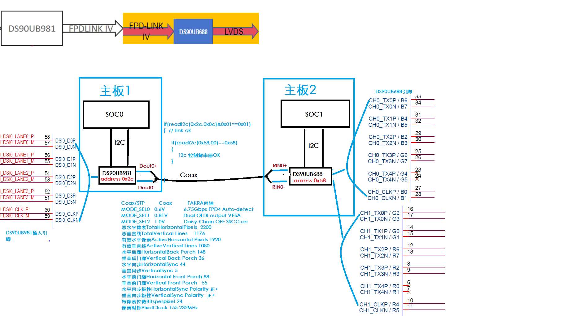
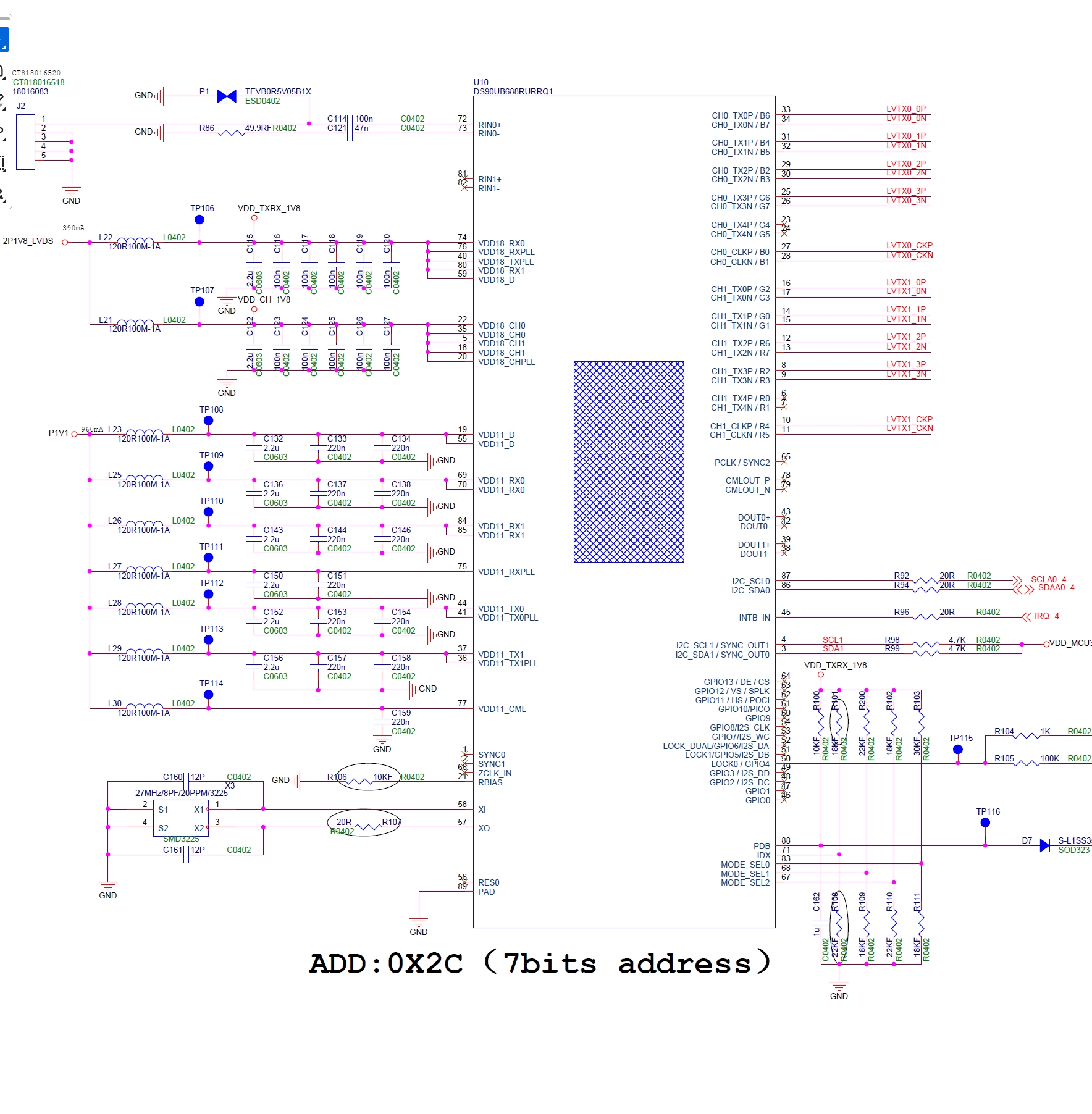
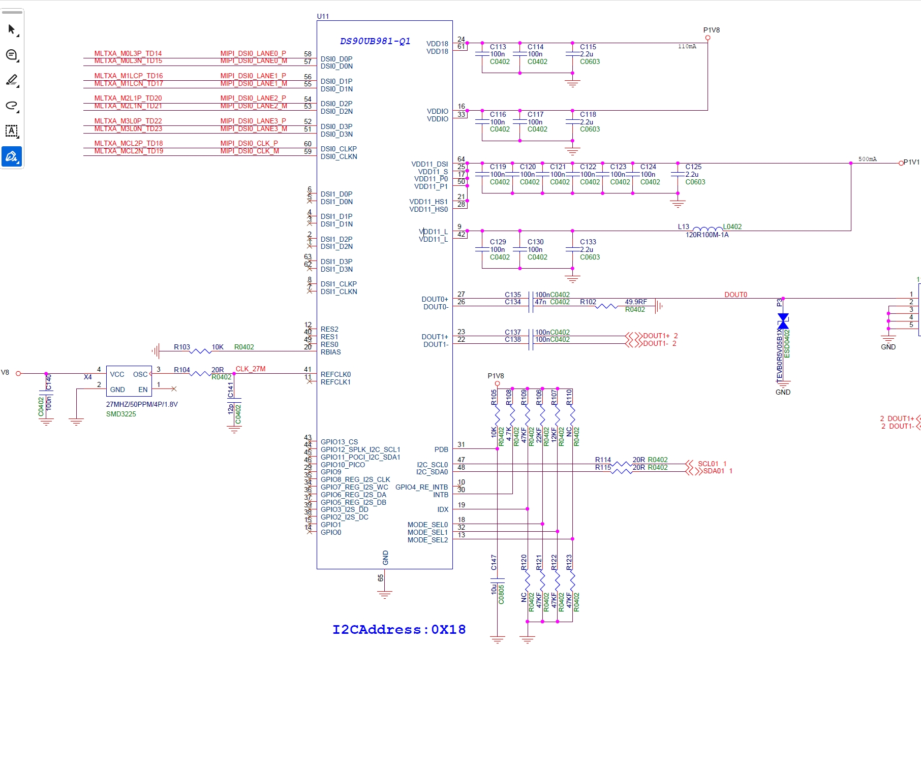
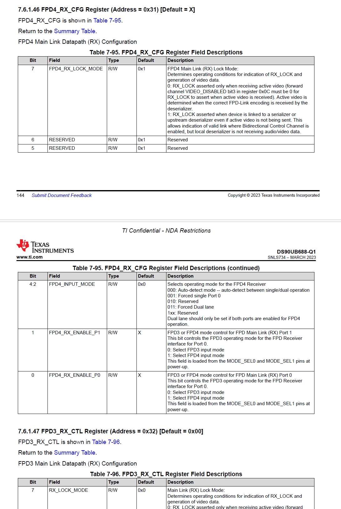
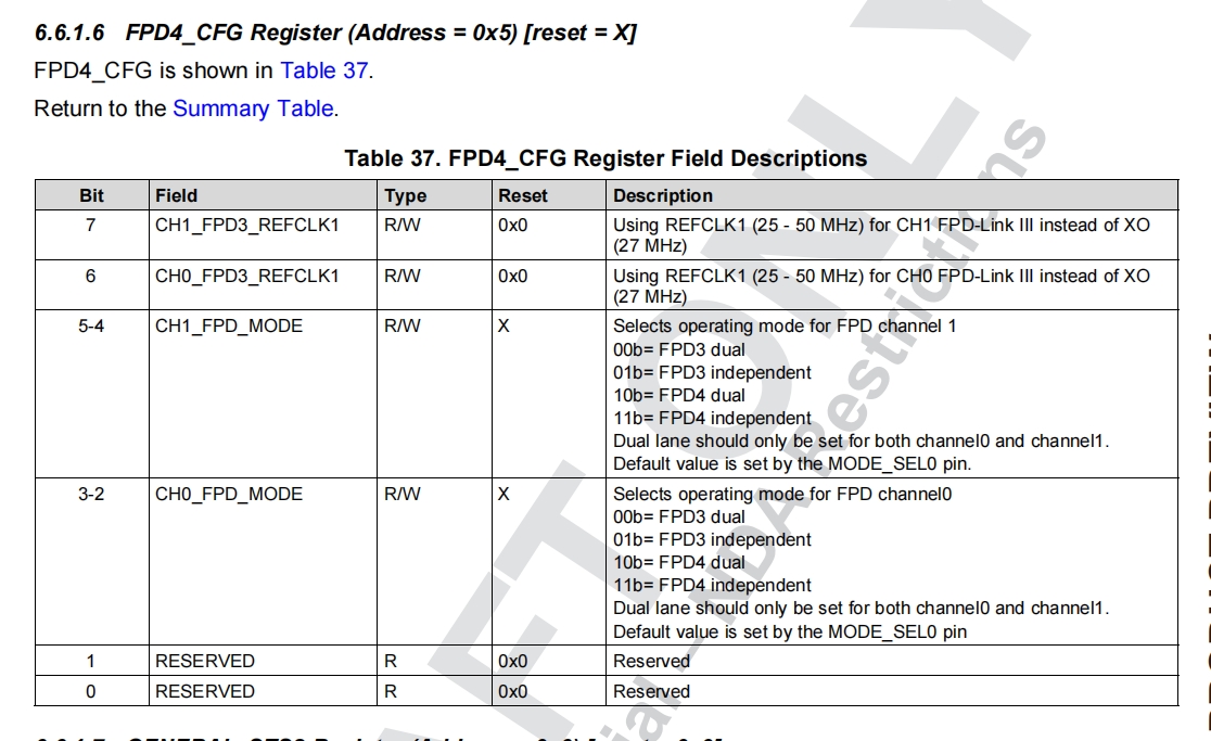
你好,老师,目前遇到问题。串行器DS90UB981 通过(FPDLINK 4 )同轴线相连解串器DS90UB688. 解串器 WriteI2C(688_ADDR, 0x31, 0x85/0X87);  //FPD4_RX_CFG 配置 强制单链路/自动 Port0, 端口0/1 FPD4使能。 串行器配置成WriteI2C(981_ADDR, 0x05, 0x0b); ,串行器和解串器就LINK 不上, 通过I2C 通过981透传去控制688 ,I2C也不通,UB688 LOCK引脚也为低电平, 但是 ub688解串器 WriteI2C(688_ADDR, 0x31, 0xe7); 就可以LINK  I2C也透传OK ,解串器688,引脚LOCK 也为高电平。  请问UB688 寄存器0X31 具体怎么配置。文档Bit5/bit6 是预留没有说明。    按照 解串器0X31配置为0xe7  串行器  0X05配置为0x0b , u688LOCK引脚为高电平。(串行器配置内置Pattern通过DOUT0+/DOUT0-),UB688  CH0 CH1 通道 只有时钟有波形,数据引脚没有波形。这是我配置串行器参数DS90UB981初始化.txt   请问是怎么回事。帮指点一下,解串器UB688 这边需要怎样配置?谢谢


OUdfk8JK6u.png

  • 已经收到了您的案例,调查需要些时间,感谢您的耐心等待。

  • 我目前还在对此进行审查,所以明天会向您更新情况。在此期间,您能否再次确认一下您是如何设置 SER 寄存器 0x5 的?看起来您将其设置为 0xB 的值,但根据您的描述,我认为您可能想要将其设置为 0x2C 而不是 0xB。当您将其设置为 0xB 时,会缺失第 0 和第 1 位,所以设置并不正确。
    从总体上看,如果绑带安装正确,这些设备应该会自动锁定。我会查看原理图,同时也会检查您添加的初始化脚本以及绑带的情况。

  • 老师你好,我写错了,我忘了写往左偏移2, 就是写0x2c 。 请问我提供的参数还有其他地方有问题吗?  解串器UB688 0x31 配值多少?

  • 这些图纸之前是否曾提交过以供审查呢?我仔细查看后发现了一些不太正常的地方。
    首先,我认为您遇到锁死问题的原因在于 688 板上的 MODE_SEL0 端口连接的电压分压电路存在错误。该端口的上拉电阻为 30 千欧姆,下拉电阻为 18 千欧姆。这样就形成了 0.375 的电压比,这与 MODE_SEL0 的任何选项都不匹配。请您让客户将此设置更改为使用推荐的电阻组合之一。
    其次,从这些截图来看,似乎 I2C 线路上并没有任何上拉电阻。有可能它们位于电路图的其他部分,但我并未看到它们与任何设备相连。

    将此寄存器设置为 0xE5 或 0xE7 是可以的;然而,这并非获取锁的推荐方法。获取锁的最佳方式是设置正确的锁带值,并允许设备自动锁定。

    这似乎是一份全新的编写好的脚本。对于 FPD4 设备的编程和初始化操作,应使用我们的 ScriptGen 工具来生成初始化脚本。这样就能根据客户提供的信息生成一个包含所有正确顺序和寄存器写入操作的 Python 平台脚本。

    这是我配置串行器参数DS90UB981初始化.txt   请问是怎么回事
  • 老师你好,硬件这块我们这块已经改了,原理图上发到了旧版本的。

  • 老师硬件改过来,参数配置需要如何配? 能否检查我的ds90ub981初始化.TXT 是否正常,不正确,能否修正一下。

  • 这是我生成的初始化脚本,请查看文件中的文本标题部分,如果发现有任何错误请告知我,同时请确认能否使其正常运行。

    ## TI Confidential - NDA Restrictions
    ## 
    ## Copyright 2025 Texas Instruments Incorporated. All rights reserved.
    ## 
    ## IMPORTANT: Your use of this Software is limited to those specific rights
    ## granted under the terms of a software license agreement between the user who
    ## downloaded the software, his/her employer (which must be your employer) and
    ## Texas Instruments Incorporated (the License). You may not use this Software
    ## unless you agree to abide by the terms of the License. The License limits your
    ## use, and you acknowledge, that the Software may not be modified, copied or
    ## distributed unless embedded on a Texas Instruments microcontroller which is
    ## integrated into your product. Other than for the foregoing purpose, you may
    ## not use, reproduce, copy, prepare derivative works of, modify, distribute,
    ## perform, display or sell this Software and/or its documentation for any
    ## purpose.
    ## 
    ## YOU FURTHER ACKNOWLEDGE AND AGREE THAT THE SOFTWARE AND DOCUMENTATION ARE
    ## PROVIDED AS IS WITHOUT WARRANTY OF ANY KIND, EITHER EXPRESS OR IMPLIED,
    ## INCLUDING WITHOUT LIMITATION, ANY WARRANTY OF MERCHANTABILITY, TITLE,
    ## NON-INFRINGEMENT AND FITNESS FOR A PARTICULAR PURPOSE. IN NO EVENT SHALL TEXAS
    ## INSTRUMENTS OR ITS LICENSORS BE LIABLE OR OBLIGATED UNDER CONTRACT,
    ## NEGLIGENCE, STRICT LIABILITY, CONTRIBUTION, BREACH OF WARRANTY, OR OTHER LEGAL
    ## EQUITABLE THEORY ANY DIRECT OR INDIRECT DAMAGES OR EXPENSES INCLUDING BUT NOT
    ## LIMITED TO ANY INCIDENTAL, SPECIAL, INDIRECT, PUNITIVE OR CONSEQUENTIAL
    ## DAMAGES, LOST PROFITS OR LOST DATA, COST OF PROCUREMENT OF SUBSTITUTE GOODS,
    ## TECHNOLOGY, SERVICES, OR ANY CLAIMS BY THIRD PARTIES (INCLUDING BUT NOT
    ## LIMITED TO ANY DEFENSE THEREOF), OR OTHER SIMILAR COSTS.
    ## 
    ## Should you have any questions regarding your right to use this Software,
    ## contact Texas Instruments Incorporated at www.TI.com.
    ## 
    
    ## DS90xx98x-Q1 Auto Script Generation Output
    ## Tool Version 6.1
    
    
    import time 
    ## Serializer: DS90Ux981-Q1
    ## User Inputs:
    ## Serializer I2C Address= 0x2c
    ## Port 0 DSI Lanes = 4
    ## Port 0 DSI Rate = 931.4 Mbps/lane
    ## FPD-Link Configuration: FPD-Link IV Single Port 0 - 6.75Gbps
    
    
    ## Number of Displays = 1
    
    ## Video Processor 0 Properties:
    ## Total Horizontal Pixels = 2200
    ## Total Vertical Lines = 1176
    ## Active Horizontal Pixels = 1920
    ## Active Vertical Lines = 1080
    ## Horizontal Back Porch = 148
    ## Vertical Back Porch = 36
    ## Horizontal Sync = 44
    ## Vertical Sync = 5
    ## Horizontal Front Porch = 88
    ## Vertical Front Porch = 55
    ## Horizontal Sync Polarity = Positive
    ## Vertical Sync Polarity = Positive
    ## Bits per pixel = 24
    ## Pixel Clock = 155.23MHz
    ## PATGEN Enabled
    
    ## Deserializer 0: DS90Ux988-Q1
    ## User Inputs:
    ## Deserializer I2C Address = 0x58
    ## Deserializer I2C Alias = 0x58
    ## 988 OLDI Output Mode
    ## Dual OLDI Mode
    ## OLDI Port 0 Bpp = 24
    ## OLDI Port 1 Bpp = 24
    ## OLDI Port 0 MAPSEL = H (MSB on D3/D4)
    ## OLDI Port 1 MAPSEL = H (MSB on D3/D4)
    ## Dual OLDI Video Source = Serializer Stream 0
    ## OLDI PATGEN Disabled
    
    ## *********************************************
    ## Set up Variables
    ## *********************************************
    serAddr = 0x2c
    desAddr0 = 0x58
    desAlias0 = 0x58
    board.WriteI2C(serAddr,0x70,desAddr0)
    board.WriteI2C(serAddr,0x78,desAlias0)
    board.WriteI2C(serAddr,0x88,0x0)
    board.WriteI2C(serAddr,0x3a,0x88) #Disable remote controller on FPD port 0 and port 1 - comment out if there is an I2C controller on the remote side
    
    ## *********************************************
    ## Check MODE Strapping
    ## *********************************************
    FPD4_Strap_Rate_P0 = 0
    FPD4_Strap_Rate_P1 = 0
    SSCG_FDEV_STRAP = 0
    SSCG_FMOD_STRAP = 0
    SSCG_TYPE_STRAP = "none"
    TX_MODE_STS = board.ReadI2C(serAddr,0x27,1)
    if TX_MODE_STS == 0:
    	print "Error: No Serializer Detected" 
    GENERAL_CFG = board.ReadI2C(serAddr,0x7,1)
    if GENERAL_CFG & 0x03 == 0x03:
    	print "MODE Strapped for ADAS Mode" 
    	FPD4_Strap_Rate_P0 = 0
    	FPD4_Strap_Rate_P1 = 0
    	TX_MODE_STRAP = "ADAS"
    else:
    	if TX_MODE_STS & 0x0F == 0x0F:
    		print "MODE Strapped for FPD III Mode" 
    		FPD4_Strap_Rate_P0 = 0
    		FPD4_Strap_Rate_P1 = 0
    		print "MODE Strapped for Independent Mode" 
    		TX_MODE_STRAP = "Independent"
    	if TX_MODE_STS & 0x0F == 0x08:
    		print "MODE Strapped for FPD IV 10.8Gbps" 
    		FPD4_Strap_Rate_P0 = 10.8
    		FPD4_Strap_Rate_P1 = 10.8
    		print "MODE Strapped for Dual Mode" 
    		TX_MODE_STRAP = "Dual"
    	if TX_MODE_STS & 0x0F == 0x09:
    		print "MODE Strapped for FPD IV 10.8Gbps" 
    		FPD4_Strap_Rate_P0 = 10.8
    		FPD4_Strap_Rate_P1 = 10.8
    		print "MODE Strapped for Independent Mode" 
    		TX_MODE_STRAP = "Independent"
    	if TX_MODE_STS & 0x0F == 0x0A or TX_MODE_STS & 0x0F == 0x0B:
    		print "Warning: Invalid MODE Strap" 
    		FPD4_Strap_Rate_P0 = 13.5
    		FPD4_Strap_Rate_P1 = 13.5
    		TX_MODE_STRAP = "Invalid"
    	if TX_MODE_STS & 0x0F == 0x0C:
    		print "MODE Strapped for FPD IV 6.75Gbps" 
    		FPD4_Strap_Rate_P0 = 6.75
    		FPD4_Strap_Rate_P1 = 6.75
    		print "MODE Strapped for Dual Mode" 
    		TX_MODE_STRAP = "Dual"
    	if TX_MODE_STS & 0x0F == 0x0D:
    		print "MODE Strapped for FPD IV 6.75Gbps" 
    		FPD4_Strap_Rate_P0 = 6.75
    		FPD4_Strap_Rate_P1 = 6.75
    		print "MODE Strapped for Independent Mode" 
    		TX_MODE_STRAP = "Independent"
    	if TX_MODE_STS & 0x0F == 0x0E:
    		print "MODE Strapped for FPD IV 3.375Gbps" 
    		FPD4_Strap_Rate_P0 = 3.375
    		FPD4_Strap_Rate_P1 = 3.375
    		print "MODE Strapped for Independent Mode" 
    		TX_MODE_STRAP = "Independent"
    
    ## *********************************************
    ## Program DSI Configs
    ## *********************************************
    
    Reg_value = board.ReadI2C(serAddr,0x2,1)
    Reg_value = Reg_value | 0x8
    board.WriteI2C(serAddr,0x2,Reg_value) #Disable DSI
    
    board.WriteI2C(serAddr,0x2d,0x1) #Select port 0
    board.WriteI2C(serAddr,0x40,0x10) #Change indirect page to page 4
    board.WriteI2C(serAddr,0x41,0x5)
    board.WriteI2C(serAddr,0x42,0x18) #Port 0 TSKIP value:12 
    
    Reg_value = board.ReadI2C(serAddr,0x4f,1)
    Reg_value = Reg_value & 0x73
    Reg_value = Reg_value | 0x8c
    board.WriteI2C(serAddr,0x4f,Reg_value) #Set number of lanes and continuous or non-continuous
    
    board.WriteI2C(serAddr,0x2d,0x3) #Select write port 0 and 1
    board.WriteI2C(serAddr,0xbd,0x0) #Set DSI source for the Video processors 0 and 1
    board.WriteI2C(serAddr,0xbe,0x0) #Set DSI source for the Video processors 2 and 3
    board.WriteI2C(serAddr,0x2d,0x1) #Select port 0
    
    
    ## *********************************************
    ## Program SER to FPD-Link IV mode
    ## *********************************************
    if TX_MODE_STRAP == "ADAS":
    	print "Override to IVI Mode"
    	board.WriteI2C(serAddr,0x2d,0x3) #Select Both Ports
    	board.WriteI2C(serAddr,0x07,GENERAL_CFG & 0xFC) # Set IVI Mode
    TX_MODE = "Single Port 0"
    board.WriteI2C(serAddr,0x5b,0x23) #Disable FPD3 FIFO pass through
    if TX_MODE != TX_MODE_STRAP:
    	print "Override to Single Port 0 Mode"
    	board.WriteI2C(serAddr,0x5,0x2c) #Force FPD4_TX single port 0 mode
    	board.WriteI2C(serAddr,0x1,0x1) #Soft Reset SER
    	time.sleep(0.04)
    
    ## *********************************************
    ## Set up FPD IV PLL Settings
    ## *********************************************
    FPD0_Rate = 6.75
    SSCG_FDEV_0 = 0
    SSCG_FMOD_0 = 0
    SSCG_TYPE_0 = "none"
    if (FPD0_Rate != FPD4_Strap_Rate_P0) or (SSCG_FDEV_STRAP != SSCG_FDEV_0) or (SSCG_FMOD_STRAP != SSCG_FMOD_0) or (SSCG_TYPE_STRAP != SSCG_TYPE_0):
    	print "FPD IV script rate mismatched with strapped rate for FPD Port 0 - Overriding Port 0 PLL settings"
    	board.WriteI2C(serAddr,0x40,0x8) #Select PLL reg page
    	board.WriteI2C(serAddr,0x41,0x1b)
    	board.WriteI2C(serAddr,0x42,0x8) #Disable PLL0
    board.WriteI2C(serAddr,0x40,0x8) #Select PLL reg page
    board.WriteI2C(serAddr,0x41,0x5b)
    board.WriteI2C(serAddr,0x42,0x8) #Disable PLL1
    if GENERAL_CFG & 0x03 == 0x03:
    	board.WriteI2C(serAddr,0x40,0x24)
    	board.WriteI2C(serAddr,0x41,0x84)
    	board.WriteI2C(serAddr,0x42,0x2) #Switch encoder from ADAS to IVI on port 0
    if (FPD0_Rate != FPD4_Strap_Rate_P0) or (SSCG_FDEV_STRAP != SSCG_FDEV_0) or (SSCG_FMOD_STRAP != SSCG_FMOD_0) or (SSCG_TYPE_STRAP != SSCG_TYPE_0):
    	board.WriteI2C(serAddr,0x40,0x8) #Select PLL page
    	board.WriteI2C(serAddr,0x41,0x5) #Select Ncount Reg
    	board.WriteI2C(serAddr,0x42,0x7d) #Set Ncount
    	board.WriteI2C(serAddr,0x41,0x13) #Select post div reg
    	board.WriteI2C(serAddr,0x42,0x90) #Set post div for 6.75 Gbps
    	board.WriteI2C(serAddr,0x2d,0x1) #Select write reg to port 0
    	board.WriteI2C(serAddr,0x6a,0xa) #set BC sampling rate
    	board.WriteI2C(serAddr,0x6e,0x80) #set BC fractional sampling
    	board.WriteI2C(serAddr,0x40,0x4) #Select FPD page and set BC settings for FPD IV port 0
    	board.WriteI2C(serAddr,0x41,0x6)
    	board.WriteI2C(serAddr,0x42,0x0)
    	board.WriteI2C(serAddr,0x41,0xd)
    	board.WriteI2C(serAddr,0x42,0x34)
    	board.WriteI2C(serAddr,0x41,0xe)
    	board.WriteI2C(serAddr,0x42,0x53)
    if (FPD0_Rate != FPD4_Strap_Rate_P0) or (SSCG_FDEV_STRAP != SSCG_FDEV_0) or (SSCG_FMOD_STRAP != SSCG_FMOD_0) or (SSCG_TYPE_STRAP != SSCG_TYPE_0):
    	board.WriteI2C(serAddr,0x2,0x11) #Set HALFRATE_MODE Override
    	board.WriteI2C(serAddr,0x2,0x51) #Set HALFRATE_MODE
    	board.WriteI2C(serAddr,0x2,0x50) #Unset HALFRATE_MODE Override
    
    if (FPD0_Rate != FPD4_Strap_Rate_P0) or (SSCG_FDEV_STRAP != SSCG_FDEV_0) or (SSCG_FMOD_STRAP != SSCG_FMOD_0) or (SSCG_TYPE_STRAP != SSCG_TYPE_0):
    	board.WriteI2C(serAddr,0x40,0x8) #Zero out fractional PLL for port 0
    	board.WriteI2C(serAddr,0x41,0x4)
    	board.WriteI2C(serAddr,0x42,0x1)
    	board.WriteI2C(serAddr,0x41,0x14)
    	board.WriteI2C(serAddr,0x42,0x80)
    	board.WriteI2C(serAddr,0x41,0x15)
    	board.WriteI2C(serAddr,0x42,0x0)
    	board.WriteI2C(serAddr,0x41,0x16)
    	board.WriteI2C(serAddr,0x42,0x0)
    	board.WriteI2C(serAddr,0x41,0x17)
    	board.WriteI2C(serAddr,0x42,0x0)
    	board.WriteI2C(serAddr,0x41,0x18)
    	board.WriteI2C(serAddr,0x42,0xf6)
    	board.WriteI2C(serAddr,0x41,0x19)
    	board.WriteI2C(serAddr,0x42,0xff)
    	board.WriteI2C(serAddr,0x41,0x1a)
    	board.WriteI2C(serAddr,0x42,0xff)
    	board.WriteI2C(serAddr,0x41,0x1e)
    	board.WriteI2C(serAddr,0x42,0x0)
    	board.WriteI2C(serAddr,0x41,0x1f)
    	board.WriteI2C(serAddr,0x42,0x0)
    	board.WriteI2C(serAddr,0x41,0x20)
    	board.WriteI2C(serAddr,0x42,0x0)
    
    ## *********************************************
    ## Configure and Enable PLLs
    ## *********************************************
    if (FPD0_Rate != FPD4_Strap_Rate_P0) or (SSCG_FDEV_STRAP != SSCG_FDEV_0) or (SSCG_FMOD_STRAP != SSCG_FMOD_0) or (SSCG_TYPE_STRAP != SSCG_TYPE_0):
    	board.WriteI2C(serAddr,0x40,0x8) #Select PLL page
    	board.WriteI2C(serAddr,0x41,0xe) #Select VCO reg
    	board.WriteI2C(serAddr,0x42,0xc7) #Set VCO
    if (FPD0_Rate != FPD4_Strap_Rate_P0) or (SSCG_FDEV_STRAP != SSCG_FDEV_0) or (SSCG_FMOD_STRAP != SSCG_FMOD_0) or (SSCG_TYPE_STRAP != SSCG_TYPE_0):
    	board.WriteI2C(serAddr,0x1,0x30) #soft reset PLL
    if (FPD0_Rate != FPD4_Strap_Rate_P0) or (SSCG_FDEV_STRAP != SSCG_FDEV_0) or (SSCG_FMOD_STRAP != SSCG_FMOD_0) or (SSCG_TYPE_STRAP != SSCG_TYPE_0):
    	board.WriteI2C(serAddr,0x40,0x8) #Select PLL page
    	board.WriteI2C(serAddr,0x41,0x1b)
    	board.WriteI2C(serAddr,0x42,0x0) #Enable PLL0
    if (FPD0_Rate != FPD4_Strap_Rate_P0) or (SSCG_FDEV_STRAP != SSCG_FDEV_0) or (SSCG_FMOD_STRAP != SSCG_FMOD_0) or (SSCG_TYPE_STRAP != SSCG_TYPE_0):
    	board.WriteI2C(serAddr,0x1,0x1) #soft reset Ser
    	time.sleep(0.04)
    	print("Enable I2C Passthrough")
    	I2C_PASS_THROUGH = board.ReadI2C(serAddr,0x7,1)
    	I2C_PASS_THROUGH_MASK = 0x08
    	I2C_PASS_THROUGH_REG = I2C_PASS_THROUGH | I2C_PASS_THROUGH_MASK
    	board.WriteI2C(serAddr,0x07,I2C_PASS_THROUGH_REG) #Enable I2C Passthrough
    	board.WriteI2C(desAlias0,0x1,0x1) #Soft reset Des
    	time.sleep(0.04)
    else:
    	print("Enable I2C Passthrough")
    	I2C_PASS_THROUGH = board.ReadI2C(serAddr,0x7,1)
    	I2C_PASS_THROUGH_MASK = 0x08
    	I2C_PASS_THROUGH_REG = I2C_PASS_THROUGH | I2C_PASS_THROUGH_MASK
    	board.WriteI2C(serAddr,0x07,I2C_PASS_THROUGH_REG) #Enable I2C Passthrough
    ## *********************************************
    ## Enable I2C Passthrough
    ## *********************************************
    print("Enable I2C Passthrough")
    I2C_PASS_THROUGH = board.ReadI2C(serAddr,0x7,1)
    I2C_PASS_THROUGH_MASK = 0x08
    I2C_PASS_THROUGH_REG = I2C_PASS_THROUGH | I2C_PASS_THROUGH_MASK
    board.WriteI2C(serAddr,0x07,I2C_PASS_THROUGH_REG) #Enable I2C Passthrough
    
    ## *********************************************
    ## Program VP Configs
    ## *********************************************
    print("Configure Video Processors")
    # Configure VP 0
    board.WriteI2C(serAddr,0x40,0x32)
    board.WriteI2C(serAddr,0x41,0x2)
    board.WriteI2C(serAddr,0x42,0x80) #DP H Active
    board.WriteI2C(serAddr,0x42,0x7) #DP H Active
    board.WriteI2C(serAddr,0x41,0x10)
    board.WriteI2C(serAddr,0x42,0x80) #Horizontal Active
    board.WriteI2C(serAddr,0x42,0x7) #Horizontal Active
    board.WriteI2C(serAddr,0x42,0x94) #Horizontal Back Porch
    board.WriteI2C(serAddr,0x42,0x0) #Horizontal Back Porch
    board.WriteI2C(serAddr,0x42,0x2c) #Horizontal Sync
    board.WriteI2C(serAddr,0x42,0x0) #Horizontal Sync
    board.WriteI2C(serAddr,0x42,0x98) #Horizontal Total
    board.WriteI2C(serAddr,0x42,0x8) #Horizontal Total
    board.WriteI2C(serAddr,0x42,0x38) #Vertical Active
    board.WriteI2C(serAddr,0x42,0x4) #Vertical Active
    board.WriteI2C(serAddr,0x42,0x24) #Vertical Back Porch
    board.WriteI2C(serAddr,0x42,0x0) #Vertical Back Porch
    board.WriteI2C(serAddr,0x42,0x5) #Vertical Sync
    board.WriteI2C(serAddr,0x42,0x0) #Vertical Sync
    board.WriteI2C(serAddr,0x42,0x37) #Vertical Front Porch
    board.WriteI2C(serAddr,0x42,0x0) #Vertical Front Porch
    board.WriteI2C(serAddr,0x41,0x27)
    board.WriteI2C(serAddr,0x42,0x0) #HSYNC Polarity = +, VSYNC Polarity = +
    # Video Processor Clock = 38.8092041016
    # Video Processor Pixel Clock = 155.236816406
    board.WriteI2C(serAddr,0x41,0x23) #M/N Register
    board.WriteI2C(serAddr,0x42,0x70) #M value = 7536
    board.WriteI2C(serAddr,0x42,0x1d) #M value = 7536
    board.WriteI2C(serAddr,0x42,0xf) #N value
    
    
    ## *********************************************
    ## Enable PATGEN
    ## *********************************************
    board.WriteI2C(serAddr,0x40,0x30)
    board.WriteI2C(serAddr,0x41,0x29)
    board.WriteI2C(serAddr,0x42,0x8) #Set PATGEN Color Depth to 24bpp for VP0
    board.WriteI2C(serAddr,0x41,0x28)
    # print("Enable PATGEN on VP0")
    # board.WriteI2C(serAddr,0x42,0x95) #Enable PATGEN on VP0 - Comment out this line to disable PATGEN and enable end to end video
    
    ## *********************************************
    ## Enable VPs
    ## *********************************************
    print("Enable Video Processors")
    board.WriteI2C(serAddr,0x43,0x0) #Set number of VPs used = 1
    board.WriteI2C(serAddr,0x44,0x1) #Enable video processors
    
    ## *********************************************
    ## Check if VP is synchronized to DP input
    ## *********************************************
    time.sleep(0.1) # Delay for VPs to sync to DP source
    
    retry = 0
    
    board.WriteI2C(serAddr,0x40,0x31) #Select VP Page
    board.WriteI2C(serAddr,0x41,0x28)
    PATGEN_VP0 = board.ReadI2C(serAddr,0x42,1)
    if ((PATGEN_VP0 & 0x01) == 1):
    	print "VP0 sync status bypassed since PATGEN is enabled"
    	VP0sts = 1
    else:
    	board.WriteI2C(serAddr,0x41,0x30)
    	VP0sts = board.ReadI2C(serAddr,0x42,1)
    	print "VP0sts =",(VP0sts & 0x01)
    	while ((VP0sts & 0x01) == 0) and retry < 10:
    		print "VP0 Not Synced - Delaying 100ms. Retry =", retry # Can be adjusted based on video source
    		time.sleep(0.1)
    		board.WriteI2C(serAddr,0x41,0x30)
    		VP0sts = board.ReadI2C(serAddr,0x42,1)
    		retry = retry + 1
    	if ((VP0sts & 0x01) == 1) and retry < 10:
    		print "VP0 Synced"
    	else:
    		print "Unable to achieve VP0 sync"
    
    ## *********************************************
    ## Configure Serializer TX Link Layer
    ## *********************************************
    print("Configure serializer TX link layer")
    board.WriteI2C(serAddr,0x40,0x2e) #Link layer Reg page
    board.WriteI2C(serAddr,0x41,0x1) #Link layer 0 stream enable
    board.WriteI2C(serAddr,0x42,0x1) #Link layer 0 stream enable
    board.WriteI2C(serAddr,0x41,0x6) #Link layer 0 time slot 0
    board.WriteI2C(serAddr,0x42,0x41) #Link layer 0 time slot
    board.WriteI2C(serAddr,0x41,0x20) #Set Link layer vp bpp
    board.WriteI2C(serAddr,0x42,0x55) #Set Link layer vp bpp according to VP Bit per pixel
    board.WriteI2C(serAddr,0x41,0x0) #Link layer 0 enable
    board.WriteI2C(serAddr,0x42,0x3) #Link layer 0 enable
    
    
    Reg_value = board.ReadI2C(serAddr,0x2,1)
    Reg_value = Reg_value & 0xf7
    board.WriteI2C(serAddr,0x2,Reg_value) #Enable DSI
    
    
    ## *********************************************
    ## Clear CRC errors from initial link process
    ## *********************************************
    print("Clear CRC errors from initial link process")
    
    Reg_value = board.ReadI2C(serAddr,0x2,1)
    Reg_value = Reg_value | 0x20
    board.WriteI2C(serAddr,0x2,Reg_value) #CRC Error Reset
    
    Reg_value = board.ReadI2C(serAddr,0x2,1)
    Reg_value = Reg_value & 0xdf
    board.WriteI2C(serAddr,0x2,Reg_value) #CRC Error Reset Clear
    
    board.WriteI2C(serAddr,0x2d,0x1)
    
    ## *********************************************
    ## Check for DES0 Communication
    ## *********************************************
    DES_READBACK = board.ReadI2C(desAlias0,0x0,1)
    if DES_READBACK == 0:
    	print "Error - no DES detected"
    else:
    	print "Deserializer detected successfully"
    
    ## *********************************************
    ## Read Deserializer 0 Temp
    ## *********************************************
    print("Configure deserializer 0 temp ramp optimizations")
    board.WriteI2C(desAlias0,0x40,0x6c)
    board.WriteI2C(desAlias0,0x41,0xd)
    board.WriteI2C(desAlias0,0x42,0x0)
    board.WriteI2C(desAlias0,0x41,0x13)
    TEMP_FINAL = board.ReadI2C(desAlias0,0x42,1)
    if TEMP_FINAL != 0:
    	TEMP_FINAL_C = 2*TEMP_FINAL - 273
    	print "Deserializer 0 starting temp =", TEMP_FINAL_C, "C"
    else:
    	print "DES Temp Invalid"
    ## *********************************************
    ## Set up Deserializer 0 Temp Ramp Optimizations
    ## *********************************************
    Efuse_TS_CODE = 2
    Ramp_UP_Range_CODES_Needed = int((150-TEMP_FINAL_C)/(190/11)) + 1
    Ramp_DN_Range_CODES_Needed = int((TEMP_FINAL_C-30)/(190/11)) + 1
    Ramp_UP_CAP_DELTA = Ramp_UP_Range_CODES_Needed - 4
    Ramp_DN_CAP_DELTA = Ramp_DN_Range_CODES_Needed - 7
    
    board.WriteI2C(desAlias0,0x40,0x3c)
    board.WriteI2C(desAlias0,0x41,0xf5)
    board.WriteI2C(desAlias0,0x42,(Efuse_TS_CODE<<4)+1) # Override TS_CODE Efuse Code
    if Ramp_UP_CAP_DELTA > 0:
    	print("Adjusting ramp up and resetting DES")
    	TS_CODE_UP = Efuse_TS_CODE - Ramp_UP_CAP_DELTA
    	if TS_CODE_UP < 0:
    		TS_CODE_UP = 0
    	board.WriteI2C(desAlias0,0x41,0xf5)
    	rb = board.ReadI2C(desAlias0,0x42,1)
    	rb &= 0x8F
    	rb |= (TS_CODE_UP << 4)
    	board.WriteI2C(desAlias0,0x42,rb)
    	rb = board.ReadI2C(desAlias0,0x42,1)
    	rb &= 0xFE
    	rb |= 0x01
    	board.WriteI2C(desAlias0,0x42,rb)
    	board.WriteI2C(desAlias0,0x1,0x1)
    	time.sleep(0.04)
    if Ramp_DN_CAP_DELTA > 0:
    	print("Adjusting ramp down and resetting DES")
    	TS_CODE_DN = Efuse_TS_CODE + Ramp_DN_CAP_DELTA
    	if TS_CODE_DN >= 7:
    		TS_CODE_DN = 7
    	board.WriteI2C(desAlias0,0x41,0xf5)
    	rb = board.ReadI2C(desAlias0,0x42,1)
    	rb &= 0x8F
    	rb |= (TS_CODE_DN << 4)
    	board.WriteI2C(desAlias0,0x42,rb)
    	rb = board.ReadI2C(desAlias0,0x42,1)
    	rb &= 0xFE
    	rb |= 0x01
    	board.WriteI2C(desAlias0,0x42,rb)
    	board.WriteI2C(desAlias0,0x1,0x1)
    	time.sleep(0.04)
    
    ## *********************************************
    ## Hold Des DTG in reset
    ## *********************************************
    print("Hold Des 0 DTG in reset and configure video settings")
    board.WriteI2C(desAlias0,0x40,0x50) #Select DTG Page
    board.WriteI2C(desAlias0,0x41,0x32)
    board.WriteI2C(desAlias0,0x42,0x6) #Hold Local Display Output Port 0 DTG in Reset
    board.WriteI2C(desAlias0,0x41,0x62)
    board.WriteI2C(desAlias0,0x42,0x6) #Hold Local Display Output Port 1 DTG in Reset
    
    
    ## *********************************************
    ## Disable Stream Mapping
    ## *********************************************
    board.WriteI2C(desAlias0,0xe,0x3) #Select both Output Ports
    board.WriteI2C(desAlias0,0xd0,0x0) #Disable FPD4 video forward to Output Port
    board.WriteI2C(desAlias0,0xd7,0x0) #Disable FPD3 video forward to Output Port
    
    
    ## *********************************************
    ## Setup DTG for port 0
    ## *********************************************
    board.WriteI2C(desAlias0,0x40,0x50) #Select DTG Page
    board.WriteI2C(desAlias0,0x41,0x20)
    board.WriteI2C(desAlias0,0x42,0x53) #Set up Local Display DTG BPP, Sync Polarities, and Measurement Type
    board.WriteI2C(desAlias0,0x41,0x29) #Set Hstart
    board.WriteI2C(desAlias0,0x42,0x80) #Hstart upper byte
    board.WriteI2C(desAlias0,0x41,0x2a)
    board.WriteI2C(desAlias0,0x42,0xc0) #Hstart lower byte
    board.WriteI2C(desAlias0,0x41,0x2f) #Set HSW
    board.WriteI2C(desAlias0,0x42,0x40) #HSW upper byte
    board.WriteI2C(desAlias0,0x41,0x30)
    board.WriteI2C(desAlias0,0x42,0x2c) #HSW lower byte
    
    
    ## *********************************************
    ## Map video to display output
    ## *********************************************
    board.WriteI2C(desAlias0,0xe,0x3) #Select both Output Ports
    board.WriteI2C(desAlias0,0xd0,0xc) #Enable FPD_RX video forward to Output Port
    board.WriteI2C(desAlias0,0xd1,0xf) #Every stream forwarded on DC
    board.WriteI2C(desAlias0,0xd6,0x0) #Send Stream 0 to Output Port 0 and Send Stream 0 to Output Port 1
    board.WriteI2C(desAlias0,0xd7,0x0) #FPD3 to local display output mapping disabled
    board.WriteI2C(desAlias0,0xe,0x1) #Select Port 0 
    
    
    ## *********************************************
    ## Configure 988 Display
    ## *********************************************
    board.WriteI2C(desAlias0,0x40,0x2c) #Configure OLDI/RGB Port Settings
    board.WriteI2C(desAlias0,0x41,0x0)
    board.WriteI2C(desAlias0,0x42,0x2f)
    board.WriteI2C(desAlias0,0x41,0x1)
    board.WriteI2C(desAlias0,0x42,0x2f)
    board.WriteI2C(desAlias0,0x40,0x2e) #Configure OLDI/RGB PLL
    board.WriteI2C(desAlias0,0x41,0x8)
    board.WriteI2C(desAlias0,0x42,0x3e) #PLL_NUM23_16
    board.WriteI2C(desAlias0,0x42,0xaa) #PLL_NUM15_8
    board.WriteI2C(desAlias0,0x42,0x29) #PLL_NUM7_0
    board.WriteI2C(desAlias0,0x42,0xff) #PLL_DEN23_16
    board.WriteI2C(desAlias0,0x42,0xf7) #PLL_DEN15_8
    board.WriteI2C(desAlias0,0x42,0xbc) #PLL_DEN7_0
    board.WriteI2C(desAlias0,0x41,0x18)
    board.WriteI2C(desAlias0,0x42,0x28) #PLL_NDIV
    board.WriteI2C(desAlias0,0x41,0x2d)
    board.WriteI2C(desAlias0,0x42,0x11) #TX_SEL_CLKDIV
    
    
    ## *********************************************
    ## Release Des DTG reset
    ## *********************************************
    print("Release Des 0 DTG reset and enable video output")
    board.WriteI2C(desAlias0,0x40,0x50) #Select DTG Page
    board.WriteI2C(desAlias0,0x41,0x32)
    board.WriteI2C(desAlias0,0x42,0x5) #Release Local Display Output Port 0 DTG with WDT Enabled
    board.WriteI2C(desAlias0,0x41,0x62)
    board.WriteI2C(desAlias0,0x42,0x5) #Release Local Display Output Port 1 DTG with WDT Enabled
    
    
    ## *********************************************
    ## Enable OLDI Output
    ## *********************************************
    board.WriteI2C(desAlias0,0x1,0x40) #OLDI Reset
    board.WriteI2C(desAlias0,0x40,0x2c) #Enable OLDI/RGB
    board.WriteI2C(desAlias0,0x41,0x2)
    board.WriteI2C(desAlias0,0x42,0x14)
    board.WriteI2C(desAlias0,0x41,0x2) #Toggle OLDI_SER_EN for Dual OLDI Mode
    board.WriteI2C(desAlias0,0x42,0x4)
    board.WriteI2C(desAlias0,0x42,0x14)
    board.WriteI2C(desAlias0,0x41,0x20) #P0 TX_EN
    board.WriteI2C(desAlias0,0x42,0x80)
    board.WriteI2C(desAlias0,0x41,0x22) #P1 TX_EN
    board.WriteI2C(desAlias0,0x42,0x80)


  • 老师你好,现在参数981输入内置信号给UB688 可以显示,但是目前有个问题就是显示画面下边有一些虚像在斗都动, 我想看下是981信号问题,还是UB688的问题,现在我想UB688自出内置彩条, 在你配置的基础上,我配置了一组688参数内置Pattern 

    WriteI2C(desAlias0, 0x40, 0x50); // Page_20

    // 设置 PGCFG: 24-bit, 外部时序 (0x0c)
    WriteI2C(desAlias0, 0x41, 0x01); WriteI2C(desAlias0, 0x42, 0x0c);

    // 设置 PGIA: 自动递增模式 (0x86)
    WriteI2C(desAlias0, 0x41, 0x02); WriteI2C(desAlias0, 0x42, 0x86);

    // 连续写入 PGID (自动递增)
    // THW (总水平像素) = 2200 (0x0898) -> 先低位 0x98, 再高位 0x08
    WriteI2C(desAlias0, 0x42, 0x98); // THW 低位
    WriteI2C(desAlias0, 0x42, 0x08); // THW 高位

    // TVW (总垂直线) = 1176 (0x0498) -> 低位 0x98, 高位 0x04
    WriteI2C(desAlias0, 0x42, 0x98); // TVW 低位
    WriteI2C(desAlias0, 0x42, 0x04); // TVW 高位

    // AHW (有效水平像素) = 1920 (0x0780) -> 低位 0x80, 高位 0x07
    WriteI2C(desAlias0, 0x42, 0x80); // AHW 低位
    WriteI2C(desAlias0, 0x42, 0x07); // AHW 高位

    // AVW (有效垂直线) = 1080 (0x0438) -> 低位 0x38, 高位 0x04
    WriteI2C(desAlias0, 0x42, 0x38); // AVW 低位
    WriteI2C(desAlias0, 0x42, 0x04); // AVW 高位

    // HSW (水平同步宽度) = 44 (0x002C) -> 低位 0x2C, 高位 0x00
    WriteI2C(desAlias0, 0x42, 0x2C); // HSW 低位
    WriteI2C(desAlias0, 0x42, 0x00); // HSW 高位

    // VSW (垂直同步宽度) = 5 (0x0005) -> 低位 0x05, 高位 0x00
    WriteI2C(desAlias0, 0x42, 0x05); // VSW 低位
    WriteI2C(desAlias0, 0x42, 0x00); // VSW 高位

    // HBP (水平后沿) = 148 (0x0094) -> 低位 0x94, 高位 0x00
    WriteI2C(desAlias0, 0x42, 0x94); // HBP 低位
    WriteI2C(desAlias0, 0x42, 0x00); // HBP 高位

    // VBP (垂直后沿) = 36 (0x0024) -> 低位 0x24, 高位 0x00
    WriteI2C(desAlias0, 0x42, 0x24); // VBP 低位
    WriteI2C(desAlias0, 0x42, 0x00); // VBP 高位

    // 使能 Pattern Generator (彩条)
    WriteI2C(desAlias0, 0x41, 0x00); WriteI2C(desAlias0, 0x42, 0x95); // 彩条

    ,但是不显示 。请问老师,是哪里配置问题?

  • 从文本格式来看难以判断,但至少可以确定的是您似乎没有设置 HSYNC 和 VSYNC 的极性。我已经为仅用于 DES PATGEN 的部分重新生成了一个新脚本:

    ## TI Confidential - NDA Restrictions
    ## 
    ## Copyright 2025 Texas Instruments Incorporated. All rights reserved.
    ## 
    ## IMPORTANT: Your use of this Software is limited to those specific rights
    ## granted under the terms of a software license agreement between the user who
    ## downloaded the software, his/her employer (which must be your employer) and
    ## Texas Instruments Incorporated (the License). You may not use this Software
    ## unless you agree to abide by the terms of the License. The License limits your
    ## use, and you acknowledge, that the Software may not be modified, copied or
    ## distributed unless embedded on a Texas Instruments microcontroller which is
    ## integrated into your product. Other than for the foregoing purpose, you may
    ## not use, reproduce, copy, prepare derivative works of, modify, distribute,
    ## perform, display or sell this Software and/or its documentation for any
    ## purpose.
    ## 
    ## YOU FURTHER ACKNOWLEDGE AND AGREE THAT THE SOFTWARE AND DOCUMENTATION ARE
    ## PROVIDED AS IS WITHOUT WARRANTY OF ANY KIND, EITHER EXPRESS OR IMPLIED,
    ## INCLUDING WITHOUT LIMITATION, ANY WARRANTY OF MERCHANTABILITY, TITLE,
    ## NON-INFRINGEMENT AND FITNESS FOR A PARTICULAR PURPOSE. IN NO EVENT SHALL TEXAS
    ## INSTRUMENTS OR ITS LICENSORS BE LIABLE OR OBLIGATED UNDER CONTRACT,
    ## NEGLIGENCE, STRICT LIABILITY, CONTRIBUTION, BREACH OF WARRANTY, OR OTHER LEGAL
    ## EQUITABLE THEORY ANY DIRECT OR INDIRECT DAMAGES OR EXPENSES INCLUDING BUT NOT
    ## LIMITED TO ANY INCIDENTAL, SPECIAL, INDIRECT, PUNITIVE OR CONSEQUENTIAL
    ## DAMAGES, LOST PROFITS OR LOST DATA, COST OF PROCUREMENT OF SUBSTITUTE GOODS,
    ## TECHNOLOGY, SERVICES, OR ANY CLAIMS BY THIRD PARTIES (INCLUDING BUT NOT
    ## LIMITED TO ANY DEFENSE THEREOF), OR OTHER SIMILAR COSTS.
    ## 
    ## Should you have any questions regarding your right to use this Software,
    ## contact Texas Instruments Incorporated at www.TI.com.
    ## 
    
    ## DS90xx98x-Q1 Auto Script Generation Output
    ## Tool Version 6.1
    
    
    import time 
    ## Deserializer 0: DS90Ux988-Q1
    ## User Inputs:
    ## Deserializer I2C Address = 0x58
    ## Deserializer I2C Alias = 0x58
    ## 988 OLDI Output Mode
    ## Dual OLDI Mode
    ## OLDI Port 0 Bpp = 24
    ## OLDI Port 1 Bpp = 24
    ## OLDI Port 0 MAPSEL = H (MSB on D3/D4)
    ## OLDI Port 1 MAPSEL = H (MSB on D3/D4)
    ## Dual OLDI Video Source = Serializer Stream 0
    ## OLDI PATGEN Enabled
    ## Patgen Video Properties:
    ## Total Horizontal Pixels = 2200
    ## Total Vertical Lines = 1176
    ## Active Horizontal Pixels = 1920
    ## Active Vertical Lines = 1080
    ## Horizontal Back Porch = 148
    ## Vertical Back Porch = 36
    ## Horizontal Sync = 44
    ## Vertical Sync = 5
    ## Horizontal Front Porch = 88
    ## Vertical Front Porch = 55
    ## Horizontal Sync Polarity = Positive
    ## Vertical Sync Polarity = Positive
    ## Bits per pixel = 24
    ## Pixel Clock = 155.23MHz
    
    ## *********************************************
    ## Set up Variables
    ## *********************************************
    serAddr = 0x2c
    desAddr0 = 0x58
    desAlias0 = 0x58
    
    ## *********************************************
    ## Set up FPD III SER
    ## *********************************************
    board.WriteI2C(serAddr,0x3,0x9a) #Enable I2C Passthrough - Comment this out if the intent is to communicate locally with the DES
    
    
    ## *********************************************
    ## Hold Des DTG in reset
    ## *********************************************
    print("Hold Des 0 DTG in reset and configure video settings")
    board.WriteI2C(desAlias0,0x40,0x50) #Select DTG Page
    board.WriteI2C(desAlias0,0x41,0x32)
    board.WriteI2C(desAlias0,0x42,0x6) #Hold Local Display Output Port 0 DTG in Reset
    board.WriteI2C(desAlias0,0x41,0x62)
    board.WriteI2C(desAlias0,0x42,0x6) #Hold Local Display Output Port 1 DTG in Reset
    
    
    ## *********************************************
    ## Disable Stream Mapping
    ## *********************************************
    board.WriteI2C(desAlias0,0xe,0x3) #Select both Output Ports
    board.WriteI2C(desAlias0,0xd0,0x0) #Disable FPD4 video forward to Output Port
    board.WriteI2C(desAlias0,0xd7,0x0) #Disable FPD3 video forward to Output Port
    
    
    ## *********************************************
    ## Setup DTG for port 0
    ## *********************************************
    board.WriteI2C(desAlias0,0x40,0x50) #Select DTG Page
    board.WriteI2C(desAlias0,0x41,0x20)
    board.WriteI2C(desAlias0,0x42,0x53) #Set up Local Display DTG BPP, Sync Polarities, and Measurement Type
    board.WriteI2C(desAlias0,0x41,0x29) #Set Hstart
    board.WriteI2C(desAlias0,0x42,0x80) #Hstart upper byte
    board.WriteI2C(desAlias0,0x41,0x2a)
    board.WriteI2C(desAlias0,0x42,0xc0) #Hstart lower byte
    board.WriteI2C(desAlias0,0x41,0x2f) #Set HSW
    board.WriteI2C(desAlias0,0x42,0x40) #HSW upper byte
    board.WriteI2C(desAlias0,0x41,0x30)
    board.WriteI2C(desAlias0,0x42,0x2c) #HSW lower byte
    
    
    ## *********************************************
    ## Map video to display output
    ## *********************************************
    board.WriteI2C(desAlias0,0xe,0x3) #Select both Output Ports
    board.WriteI2C(desAlias0,0xd0,0xc) #Enable FPD_RX video forward to Output Port
    board.WriteI2C(desAlias0,0xd1,0xf) #Every stream forwarded on DC
    board.WriteI2C(desAlias0,0xd6,0x0) #Send Stream 0 to Output Port 0 and Send Stream 0 to Output Port 1
    board.WriteI2C(desAlias0,0xd7,0x0) #FPD3 to local display output mapping disabled
    board.WriteI2C(desAlias0,0xe,0x1) #Select Port 0 
    
    
    ## *********************************************
    ## Set up deserializer Patgen
    ## *********************************************
    board.WriteI2C(desAlias0,0x40,0x50) #Set Patgen page
    board.WriteI2C(desAlias0,0x41,0x1) #Set patgen address
    board.WriteI2C(desAlias0,0x42,0xc) #Set bit per pixel
    board.WriteI2C(desAlias0,0x41,0x2) #Set patgen address
    board.WriteI2C(desAlias0,0x42,0x86) #Set patgen address auto increment
    board.WriteI2C(desAlias0,0x41,0x3) #Set patgen address
    board.WriteI2C(desAlias0,0x42,0x30) #Set patgen THW
    board.WriteI2C(desAlias0,0x42,0x11) #Set patgen THW
    board.WriteI2C(desAlias0,0x42,0x98) #Set patgen TVW
    board.WriteI2C(desAlias0,0x42,0x4) #Set patgen TVW
    board.WriteI2C(desAlias0,0x42,0x0) #Set patgen AHW
    board.WriteI2C(desAlias0,0x42,0xf) #Set patgen AHW
    board.WriteI2C(desAlias0,0x42,0x38) #Set patgen AVW
    board.WriteI2C(desAlias0,0x42,0x4) #Set patgen AVW
    board.WriteI2C(desAlias0,0x42,0x58) #Set patgen HSW
    board.WriteI2C(desAlias0,0x42,0x0) #Set patgen HSW
    board.WriteI2C(desAlias0,0x42,0x5) #Set patgen VSW
    board.WriteI2C(desAlias0,0x42,0x0) #Set patgen VSW
    board.WriteI2C(desAlias0,0x42,0x28) #Set patgen HBP
    board.WriteI2C(desAlias0,0x42,0x1) #Set patgen HBP
    board.WriteI2C(desAlias0,0x42,0x24) #Set patgen VBP
    board.WriteI2C(desAlias0,0x42,0x0) #Set patgen VBP
    board.WriteI2C(desAlias0,0x42,0x0) #HSYNC Polarity = +, VSYNC Polarity = +
    board.WriteI2C(desAlias0,0x41,0x0) #Set patgen address
    board.WriteI2C(desAlias0,0x42,0x95) #Enable Patgen color bar
    
    
    ## *********************************************
    ## Configure 988 Display
    ## *********************************************
    board.WriteI2C(desAlias0,0x40,0x2c) #Configure OLDI/RGB Port Settings
    board.WriteI2C(desAlias0,0x41,0x0)
    board.WriteI2C(desAlias0,0x42,0x2f)
    board.WriteI2C(desAlias0,0x41,0x1)
    board.WriteI2C(desAlias0,0x42,0x2f)
    board.WriteI2C(desAlias0,0x40,0x2e) #Configure OLDI/RGB PLL
    board.WriteI2C(desAlias0,0x41,0x8)
    board.WriteI2C(desAlias0,0x42,0x3e) #PLL_NUM23_16
    board.WriteI2C(desAlias0,0x42,0xaa) #PLL_NUM15_8
    board.WriteI2C(desAlias0,0x42,0x29) #PLL_NUM7_0
    board.WriteI2C(desAlias0,0x42,0xff) #PLL_DEN23_16
    board.WriteI2C(desAlias0,0x42,0xf7) #PLL_DEN15_8
    board.WriteI2C(desAlias0,0x42,0xbc) #PLL_DEN7_0
    board.WriteI2C(desAlias0,0x41,0x18)
    board.WriteI2C(desAlias0,0x42,0x28) #PLL_NDIV
    board.WriteI2C(desAlias0,0x41,0x2d)
    board.WriteI2C(desAlias0,0x42,0x11) #TX_SEL_CLKDIV
    
    
    ## *********************************************
    ## Release Des DTG reset
    ## *********************************************
    print("Release Des 0 DTG reset and enable video output")
    board.WriteI2C(desAlias0,0x40,0x50) #Select DTG Page
    board.WriteI2C(desAlias0,0x41,0x32)
    board.WriteI2C(desAlias0,0x42,0x5) #Release Local Display Output Port 0 DTG with WDT Enabled
    board.WriteI2C(desAlias0,0x41,0x62)
    board.WriteI2C(desAlias0,0x42,0x5) #Release Local Display Output Port 1 DTG with WDT Enabled
    
    
    ## *********************************************
    ## Enable OLDI Output
    ## *********************************************
    board.WriteI2C(desAlias0,0x1,0x40) #OLDI Reset
    board.WriteI2C(desAlias0,0x40,0x2c) #Enable OLDI/RGB
    board.WriteI2C(desAlias0,0x41,0x2)
    board.WriteI2C(desAlias0,0x42,0x14)
    board.WriteI2C(desAlias0,0x41,0x2) #Toggle OLDI_SER_EN for Dual OLDI Mode
    board.WriteI2C(desAlias0,0x42,0x4)
    board.WriteI2C(desAlias0,0x42,0x14)
    board.WriteI2C(desAlias0,0x41,0x20) #P0 TX_EN
    board.WriteI2C(desAlias0,0x42,0x80)
    board.WriteI2C(desAlias0,0x41,0x22) #P1 TX_EN
    board.WriteI2C(desAlias0,0x42,0x80)

    If you want to play with the timings to figure out the ghosting issue, you can edit lines 128 through 152. Let me know if the issue is still there with DES PATGEN and I can help debug from there.