Part Number: TCAN1042H
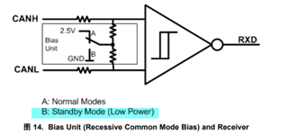
HI,我最近在选多个CAN总线应用,查到TCAN1042,我想请教的是,根据数据手册,在STB状态下,每个CANH和CANL内部一个弱的下拉电阻。我想问的是,如20个CAN链接的总线条件下,如果18个处于STB状态,只有2个在STB=0的正常状态,那么根据手册上的说法,此时会有18个电阻将总线下拉到地,而只有2个芯片以很弱的(15K)的电阻将其驱动到2.5V,那这种情况下,18个下拉电阻会将这个2.5V拉到接近地了。。。。此系统这种条件下能正常工作吗。。。。