请注意,本文内容源自机器翻译,可能存在语法或其它翻译错误,仅供参考。如需获取准确内容,请参阅链接中的英语原文或自行翻译。
器件型号:TM4C1292NCPDT 您好!
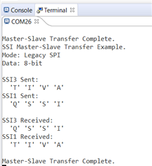
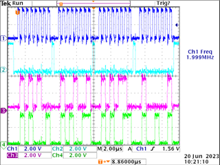
我的 SPI (使用 SSI0)示例代码在 TI Launchpad 上工作。 请参阅以下代码
#include <stdbool.h>
#include <stdint.h>
#include <inc/hw_types.h>
#include <inc/hw_ssi.h>
#include "inc/hw_memmap.h"
#include <driverlib/gpio.h>
#include "driverlib/pin_map.h"
#include "driverlib/ssi.h"
#include "driverlib/sysctl.h"
#include "driverlib/uart.h"
#include "utils/uartstdio.h"
#include <string.h>
//#include "main.h"


// Number of bytes to Send.
//
//*****************************************************************************
#define NUM_SSI_DATA 4
#define HB_ENABLE 0x0080
#define HB_CONFIG 0x0002


#ifdef DEBUG
void
__error__(char *pcFilename, uint32_t ui32Line)
{
}
#endif


uint32_t ui32SysClocks;
//*****************************************************************************
//
// This function sets up UART0 to be used for a console to display information
// as the example is running.
//
//*****************************************************************************
void InitConsole(void)
{
SysCtlPeripheralEnable(SYSCTL_PERIPH_UART0);
SysCtlPeripheralEnable(SYSCTL_PERIPH_GPIOA);
GPIOPinConfigure(GPIO_PA0_U0RX);
GPIOPinConfigure(GPIO_PA1_U0TX);
GPIOPinTypeUART(GPIO_PORTA_BASE, GPIO_PIN_0 | GPIO_PIN_1);
UARTStdioConfig(0, 9600, ui32SysClocks);
}

void InitSPI0(void){

SysCtlPeripheralEnable(SYSCTL_PERIPH_SSI0);
SysCtlPeripheralEnable(SYSCTL_PERIPH_GPIOA);

GPIOPinTypeGPIOOutput(GPIO_PORTA_BASE, GPIO_PIN_3|GPIO_PIN_2|GPIO_PIN_4);
GPIOPinTypeGPIOInput(GPIO_PORTA_BASE, GPIO_PIN_5);

SysCtlPeripheralEnable(SYSCTL_PERIPH_GPIOM);
SysCtlPeripheralEnable(SYSCTL_PERIPH_GPIOB);

GPIOPinTypeGPIOOutput(GPIO_PORTM_BASE, GPIO_PIN_5);
GPIOPadConfigSet(GPIO_PORTM_BASE, GPIO_PIN_5, GPIO_STRENGTH_12MA, GPIO_PIN_TYPE_STD_WPU );
GPIOPinWrite(GPIO_PORTM_BASE, GPIO_PIN_5, GPIO_PIN_5);//PULL UP

GPIOPinTypeGPIOOutput(GPIO_PORTB_BASE, GPIO_PIN_4);
GPIOPadConfigSet(GPIO_PORTB_BASE, GPIO_PIN_4, GPIO_STRENGTH_12MA, GPIO_PIN_TYPE_STD_WPU );
GPIOPinWrite(GPIO_PORTB_BASE, GPIO_PIN_4, GPIO_PIN_4);//PULL UP

GPIOPinConfigure(GPIO_PA2_SSI0CLK);
GPIOPinConfigure(GPIO_PA3_SSI0FSS);
GPIOPinConfigure(GPIO_PA4_SSI0XDAT0);//Tx
GPIOPinConfigure(GPIO_PA5_SSI0XDAT1);//Rx
GPIOPinTypeSSI(GPIO_PORTA_BASE, GPIO_PIN_5 | GPIO_PIN_4 | GPIO_PIN_3 | GPIO_PIN_2);
//SSIConfigSetExpClk(SSI0_BASE, ui32SysClocks, SSI_FRF_MOTO_MODE_2, SSI_MODE_MASTER, 40000000, 16);
//SSIConfigSetExpClk(SSI0_BASE, ui32SysClocks, SSI_FRF_MOTO_MODE_0, SSI_MODE_MASTER, 1500000, 16);
SSIConfigSetExpClk(SSI0_BASE, ui32SysClocks, SSI_FRF_MOTO_MODE_1, SSI_MODE_MASTER, 1500000, 16);//negative edge triggered
}

void SPI_write(const uint8_t* dataBuffer, uint8_t count){

while(count--){
SSIDataPut(SSI0_BASE, *dataBuffer++);
}
while(SSIBusy(SSI0_BASE));
}

//*****************************************************************************
//Main function Entry.
//
//*****************************************************************************
int
main(void)
{
bool pDO_Status[24];
uint8_t ui8Do_Source_Sink;

// spiConfigbus stSpiConfig;
// i2cConfigbus stI2cConfig;
uint16_t aui16SpiTxBuffer[2];
uint16_t aui16SpiRxBuffer[2][2];
uint8_t aui8I2cTxBuffer[3];
uint8_t aui8I2cRxBuffer[3];
uint8_t i;

uint8_t dataTX[4] = {0x40, 0x4F, 0x4F, 0x04};
//uint8_t dataTX = 0x40;
uint8_t count;

//ui32SysClocks = SysCtlClockFreqSet((SYSCTL_XTAL_25MHZ | SYSCTL_OSC_MAIN | SYSCTL_USE_PLL | SYSCTL_CFG_VCO_240), 120000000);
ui32SysClocks = SysCtlClockFreqSet((SYSCTL_XTAL_25MHZ | SYSCTL_OSC_MAIN | SYSCTL_USE_PLL | SYSCTL_CFG_VCO_480), 120000000);
InitConsole();

UARTprintf("SPI -> Master to Slave\n");
UARTprintf("SPI Bit_Rate: 16-bit\n\n");
InitSPI0();
SSIEnable(SSI0_BASE);

// GPIOPinWrite(GPIO_PORTM_BASE, GPIO_PIN_5, GPIO_PIN_5); //enable


dataTX[0] = (HB_ENABLE << 0 )| (HB_CONFIG << 0);//output high

SysCtlDelay(100);

SPI_write(dataTX, 1);

SysCtlDelay(100);//delay of

}

UARTprintf("Done transferring the data\r\n");
UARTprintf("----------------------------------------------------------------------");
UARTprintf("\r\n\n");

while(1);
}
但当我根据我的要求(使用 SSI3)对其进行修改时、它在 Launchpad 上不起作用。 请参见下面针对 SSI3修改的代码。
#include <stdbool.h>
#include <stdint.h>
#include <inc/hw_types.h>
#include <inc/hw_ssi.h>
#include "inc/hw_memmap.h"
#include <driverlib/gpio.h>
#include "driverlib/pin_map.h"
#include "driverlib/ssi.h"
#include "driverlib/sysctl.h"
#include "driverlib/uart.h"
#include "utils/uartstdio.h"
#include <string.h>
//#include "main.h"


// Number of bytes to Send.
//
//*****************************************************************************
#define NUM_SSI_DATA 4
#define HB_ENABLE 0x0080
#define HB_CONFIG 0x0002


#ifdef DEBUG
void
__error__(char *pcFilename, uint32_t ui32Line)
{
}
#endif


uint32_t ui32SysClocks;
//*****************************************************************************
//
// This function sets up UART0 to be used for a console to display information
// as the example is running.
//
//*****************************************************************************
void InitConsole(void)
{
SysCtlPeripheralEnable(SYSCTL_PERIPH_UART0);
SysCtlPeripheralEnable(SYSCTL_PERIPH_GPIOA);
GPIOPinConfigure(GPIO_PA0_U0RX);
GPIOPinConfigure(GPIO_PA1_U0TX);
GPIOPinTypeUART(GPIO_PORTA_BASE, GPIO_PIN_0 | GPIO_PIN_1);
UARTStdioConfig(0, 9600, ui32SysClocks);
}

void InitSPI0(void){

SysCtlPeripheralEnable(SYSCTL_PERIPH_SSI0);
SysCtlPeripheralEnable(SYSCTL_PERIPH_GPIOA);

GPIOPinTypeGPIOOutput(GPIO_PORTA_BASE, GPIO_PIN_3|GPIO_PIN_2|GPIO_PIN_4);
GPIOPinTypeGPIOInput(GPIO_PORTA_BASE, GPIO_PIN_5);

SysCtlPeripheralEnable(SYSCTL_PERIPH_GPIOM);
SysCtlPeripheralEnable(SYSCTL_PERIPH_GPIOB);

GPIOPinTypeGPIOOutput(GPIO_PORTM_BASE, GPIO_PIN_5);
GPIOPadConfigSet(GPIO_PORTM_BASE, GPIO_PIN_5, GPIO_STRENGTH_12MA, GPIO_PIN_TYPE_STD_WPU );
GPIOPinWrite(GPIO_PORTM_BASE, GPIO_PIN_5, GPIO_PIN_5);//PULL UP

GPIOPinTypeGPIOOutput(GPIO_PORTB_BASE, GPIO_PIN_4);
GPIOPadConfigSet(GPIO_PORTB_BASE, GPIO_PIN_4, GPIO_STRENGTH_12MA, GPIO_PIN_TYPE_STD_WPU );
GPIOPinWrite(GPIO_PORTB_BASE, GPIO_PIN_4, GPIO_PIN_4);//PULL UP

GPIOPinConfigure(GPIO_PA2_SSI0CLK);
GPIOPinConfigure(GPIO_PA3_SSI0FSS);
GPIOPinConfigure(GPIO_PA4_SSI0XDAT0);//Tx
GPIOPinConfigure(GPIO_PA5_SSI0XDAT1);//Rx
GPIOPinTypeSSI(GPIO_PORTA_BASE, GPIO_PIN_5 | GPIO_PIN_4 | GPIO_PIN_3 | GPIO_PIN_2);
//SSIConfigSetExpClk(SSI0_BASE, ui32SysClocks, SSI_FRF_MOTO_MODE_2, SSI_MODE_MASTER, 40000000, 16);
//SSIConfigSetExpClk(SSI0_BASE, ui32SysClocks, SSI_FRF_MOTO_MODE_0, SSI_MODE_MASTER, 1500000, 16);
SSIConfigSetExpClk(SSI0_BASE, ui32SysClocks, SSI_FRF_MOTO_MODE_1, SSI_MODE_MASTER, 1500000, 16);//negative edge triggered
}

void InitSPI3(void){

SysCtlPeripheralEnable(SYSCTL_PERIPH_SSI3);
SysCtlPeripheralEnable(SYSCTL_PERIPH_GPIOQ);
SysCtlPeripheralEnable(SYSCTL_PERIPH_GPIOP);

GPIOPinTypeGPIOOutput(GPIO_PORTQ_BASE, GPIO_PIN_2 | GPIO_PIN_0);
GPIOPinTypeGPIOInput(GPIO_PORTQ_BASE, GPIO_PIN_3);

GPIOPinTypeGPIOOutput(GPIO_PORTP_BASE, GPIO_PIN_1);//cs

GPIOPinTypeGPIOOutput(GPIO_PORTM_BASE, GPIO_PIN_5);
GPIOPadConfigSet(GPIO_PORTM_BASE, GPIO_PIN_5, GPIO_STRENGTH_12MA, GPIO_PIN_TYPE_STD_WPU );
GPIOPinWrite(GPIO_PORTM_BASE, GPIO_PIN_5, GPIO_PIN_5);//PULL UP

// GPIOPadConfigSet(GPIO_PORTM_BASE, GPIO_PIN_5, GPIO_STRENGTH_12MA, GPIO_PIN_TYPE_STD_WPU );
// GPIOPinWrite(GPIO_PORTM_BASE, GPIO_PIN_5, GPIO_PIN_5);//PULL UP

// GPIOPinTypeGPIOOutput(GPIO_PORTB_BASE, GPIO_PIN_4);
GPIOPadConfigSet(GPIO_PORTP_BASE, GPIO_PIN_1, GPIO_STRENGTH_12MA, GPIO_PIN_TYPE_STD_WPU );
GPIOPinWrite(GPIO_PORTP_BASE, GPIO_PIN_1, GPIO_PIN_1);//PULL UP

GPIOPinConfigure(GPIO_PQ0_SSI3CLK);
//GPIOPinConfigure(GPIO_PA3_SSI0FSS);
GPIOPinConfigure(GPIO_PQ2_SSI3XDAT0);//Tx
GPIOPinConfigure(GPIO_PQ3_SSI3XDAT1);//Rx
GPIOPinTypeSSI(GPIO_PORTQ_BASE, GPIO_PIN_0 | GPIO_PIN_3 | GPIO_PIN_2);
//SSIConfigSetExpClk(SSI0_BASE, ui32SysClocks, SSI_FRF_MOTO_MODE_2, SSI_MODE_MASTER, 40000000, 16);
//SSIConfigSetExpClk(SSI0_BASE, ui32SysClocks, SSI_FRF_MOTO_MODE_0, SSI_MODE_MASTER, 1500000, 16);
SSIConfigSetExpClk(SSI3_BASE, ui32SysClocks, SSI_FRF_MOTO_MODE_1, SSI_MODE_MASTER, 1500000, 16);//negative edge triggered
}

/*void SPI_write(const uint8_t* dataBuffer, uint8_t count){

while(count--){
SSIDataPut(SSI0_BASE, *dataBuffer++);
}
while(SSIBusy(SSI0_BASE));
}*/

void SPI_write_SSI3(const uint8_t* dataBuffer, uint8_t count){

while(count--){
SSIDataPut(SSI3_BASE, *dataBuffer++);
}
while(SSIBusy(SSI3_BASE));
}

//*****************************************************************************
//Main function Entry.
//
//*****************************************************************************
int
main(void)
{
bool pDO_Status[24];
uint8_t ui8Do_Source_Sink;

volatile uint32_t ui32Loop;

uint16_t aui16SpiTxBuffer[2];
uint16_t aui16SpiRxBuffer[2][2];
uint8_t aui8I2cTxBuffer[3];
uint8_t aui8I2cRxBuffer[3];
uint8_t i;

uint8_t dataTX[4] = {0x40, 0x4F, 0x4F, 0x04};
//uint8_t dataTX = 0x40;
uint8_t count;

//ui32SysClocks = SysCtlClockFreqSet((SYSCTL_XTAL_25MHZ | SYSCTL_OSC_MAIN | SYSCTL_USE_PLL | SYSCTL_CFG_VCO_240), 120000000);
ui32SysClocks = SysCtlClockFreqSet((SYSCTL_XTAL_25MHZ | SYSCTL_OSC_MAIN | SYSCTL_USE_PLL | SYSCTL_CFG_VCO_480), 120000000);
InitConsole();

UARTprintf("SPI -> Master to Slave\n");
UARTprintf("SPI Bit_Rate: 16-bit\n\n");

InitSPI3();
SSIEnable(SSI3_BASE);

dataTX[0] = (HB_ENABLE << 0 )| (HB_CONFIG << 0);//output high
GPIOPinWrite(GPIO_PORTP_BASE, GPIO_PIN_1, 0);

SysCtlDelay(100);

SPI_write_SSI3(dataTX, 1);

SysCtlDelay(100);//delay of

GPIOPinWrite(GPIO_PORTP_BASE, GPIO_PIN_1, GPIO_PIN_1);


UARTprintf("Done transferring the data\r\n");
UARTprintf("----------------------------------------------------------------------");
UARTprintf("\r\n\n");

while(1);
}
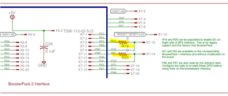
SSI3在我的原理图中用于如下所示
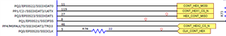
如果代码中有任何内容需要更改才能运行 SSI3、您能否提供指导?
谢谢。
Kiran