请注意,本文内容源自机器翻译,可能存在语法或其它翻译错误,仅供参考。如需获取准确内容,请参阅链接中的英语原文或自行翻译。
器件型号:TM4C123GH6PM Thread 中讨论的其他器件:EK-TM4C123GXL
工具与软件:
我 在定制电路板上有一个 TI TIVA TM4C123GH6PMIR、可在不同的代码行为我提供各种类型的随机 FaultISR ()。
无论我尝试了什么、我都无法看到缩小导致问题的范围。
我的代码基于 uart_echo 示例。
我的代码在这里、
/*
* main.c
*
* Created on: Jul 4, 2024
* Author: User
*/
#include <stdint.h>
#include <stdbool.h>
#include <string.h>
#include "inc/hw_ints.h"
#include "inc/hw_memmap.h"
#include "inc/hw_types.h"
#include "inc/hw_gpio.h"
#include "driverlib/debug.h"
#include "driverlib/fpu.h"
#include "driverlib/gpio.h"
#include "driverlib/interrupt.h"
#include "driverlib/pin_map.h"
#include "driverlib/rom.h"
#include "driverlib/rom_map.h"
#include "driverlib/sysctl.h"
#include "driverlib/uart.h"
#ifdef DEBUG
void
__error__(char *pcFilename, uint32_t ui32Line)
{
}
#endif
void GPIOPinUnlockGPIO(uint32_t ui32Port, uint8_t ui8Pins)
{
HWREG(ui32Port + GPIO_O_LOCK) = GPIO_LOCK_KEY; // Unlock the port
HWREG(ui32Port + GPIO_O_CR) |= ui8Pins; // Unlock the Pin
HWREG(ui32Port + GPIO_O_LOCK) = 0; // Lock the port
}
//*****************************************************************************
//
// The UART interrupt handler.
//
//*****************************************************************************
void
UARTIntHandler(void)
{
uint32_t ui32Status;
//
// Get the interrrupt status.
//
ui32Status = UARTIntStatus(UART0_BASE, true);
//
// Clear the asserted interrupts.
//
UARTIntClear(UART0_BASE, ui32Status);
//
// Loop while there are characters in the receive FIFO.
//
while(UARTCharsAvail(UART0_BASE))
{
//
// Read the next character from the UART and write it back to the UART.
//
UARTCharPutNonBlocking(UART0_BASE,
UARTCharGetNonBlocking(UART0_BASE));
//
// Blink the LED to show a character transfer is occurring.
//
GPIOPinWrite(GPIO_PORTF_BASE, GPIO_PIN_2, GPIO_PIN_2);
//
// Delay for 1 millisecond. Each SysCtlDelay is about 3 clocks.
//
SysCtlDelay(SysCtlClockGet() / (1000 * 3));
//
// Turn off the LED
//
GPIOPinWrite(GPIO_PORTF_BASE, GPIO_PIN_2, 0);
}
}
//*****************************************************************************
//
// Send a string to the UART.
//
//*****************************************************************************
void
UARTSend(const uint8_t *pui8Buffer, uint32_t ui32Count)
{
GPIOPinWrite(GPIO_PORTA_BASE, GPIO_PIN_2, GPIO_PIN_2);
//
// Loop while there are more characters to send.
//
while(ui32Count--)
{
//
// Write the next character to the UART.
//
UARTCharPut(UART0_BASE, *pui8Buffer++);
}
while (UARTBusy(UART0_BASE))
{
}
GPIOPinWrite(GPIO_PORTA_BASE, GPIO_PIN_2, 0);
}
int main()
{
//0. Enable lazy stacking for interrupt handlers.
FPUEnable();
FPULazyStackingEnable();
//1. Run from the internal oscillator.
SysCtlClockSet(SYSCTL_OSC_INT | SYSCTL_USE_OSC | SYSCTL_SYSDIV_1);
//2. Enable the peripherals.
SysCtlPeripheralEnable(SYSCTL_PERIPH_GPIOA);
SysCtlPeripheralEnable(SYSCTL_PERIPH_UART0);
while(!SysCtlPeripheralReady(SYSCTL_PERIPH_GPIOA))
{
}
while(!SysCtlPeripheralReady(SYSCTL_PERIPH_UART0))
{
}
//3. Set GPIO A0 and A1 as UART pins.
GPIOPinConfigure(GPIO_PA0_U0RX);
GPIOPinConfigure(GPIO_PA1_U0TX);
GPIOPinTypeUART(GPIO_PORTA_BASE, GPIO_PIN_0 | GPIO_PIN_1);
//4. Configure UART
UARTConfigSetExpClk(UART0_BASE, SysCtlClockGet(), 115200,
(UART_CONFIG_WLEN_8 | UART_CONFIG_STOP_ONE |
UART_CONFIG_PAR_NONE));
//5. Enable the UART interrupt.
IntEnable(INT_UART0);
UARTIntEnable(UART0_BASE, UART_INT_RX | UART_INT_RT);
//6. Enable the GPIO Pins.
GPIOPinUnlockGPIO(GPIO_PORTA_BASE, GPIO_PIN_2);
GPIOPinTypeGPIOOutput(GPIO_PORTA_BASE, GPIO_PIN_2); //TX EN
GPIOPinUnlockGPIO(GPIO_PORTA_BASE, GPIO_PIN_3);
GPIOPinTypeGPIOOutput(GPIO_PORTA_BASE, GPIO_PIN_3); //RX EN
GPIOPinWrite(GPIO_PORTA_BASE, GPIO_PIN_2, 0); //UART_TX_EN (Active High)
GPIOPinWrite(GPIO_PORTA_BASE, GPIO_PIN_3, 0); //UART_RX_EN (Active Low)
//7. Enable the processor interrupts.
IntMasterEnable();
while(1)
{
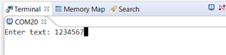
UARTSend((uint8_t *)"\033[2JEnter text: ", 16);
}
}
我的代码从 IntMasterEnable ()和 GPIOPinWrite (GPIO_PORTA_BASE、GPIO_PIN_2、GPIO_PIN_2)跳转到 FaultISR ();
我不知道到底发生了什么。 如有任何建议、将不胜感激。
谢谢!
解决了