This thread has been locked.

If you have a related question, please click the "Ask a related question" button in the top right corner. The newly created question will be automatically linked to this question.

[参考译文] TM4C123GH6PM:随机 FaultISR ()

Guru**** 1839620 points
Other Parts Discussed in Thread: EK-TM4C123GXL
请注意,本文内容源自机器翻译,可能存在语法或其它翻译错误,仅供参考。如需获取准确内容,请参阅链接中的英语原文或自行翻译。

https://e2e.ti.com/support/microcontrollers/arm-based-microcontrollers-group/arm-based-microcontrollers/f/arm-based-microcontrollers-forum/1383935/tm4c123gh6pm-random-faultisr

器件型号:TM4C123GH6PM
Thread 中讨论的其他器件:EK-TM4C123GXL

工具与软件:

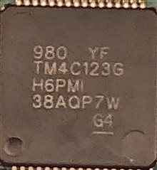
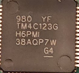
我 在定制电路板上有一个 TI TIVA TM4C123GH6PMIR、可在不同的代码行为我提供各种类型的随机 FaultISR ()。

无论我尝试了什么、我都无法看到缩小导致问题的范围。

我的代码基于 uart_echo 示例。

我的代码在这里、

/*
 * main.c
 *
 *  Created on: Jul 4, 2024
 *      Author: User
 */
#include <stdint.h>
#include <stdbool.h>
#include <string.h>
#include "inc/hw_ints.h"
#include "inc/hw_memmap.h"
#include "inc/hw_types.h"
#include "inc/hw_gpio.h"
#include "driverlib/debug.h"
#include "driverlib/fpu.h"
#include "driverlib/gpio.h"
#include "driverlib/interrupt.h"
#include "driverlib/pin_map.h"
#include "driverlib/rom.h"
#include "driverlib/rom_map.h"
#include "driverlib/sysctl.h"
#include "driverlib/uart.h"

#ifdef DEBUG
void
__error__(char *pcFilename, uint32_t ui32Line)
{
}
#endif

void GPIOPinUnlockGPIO(uint32_t ui32Port, uint8_t ui8Pins)
{
    HWREG(ui32Port + GPIO_O_LOCK) = GPIO_LOCK_KEY;      // Unlock the port
    HWREG(ui32Port + GPIO_O_CR) |= ui8Pins;             // Unlock the Pin
    HWREG(ui32Port + GPIO_O_LOCK) = 0;                  // Lock the port
}

//*****************************************************************************
//
// The UART interrupt handler.
//
//*****************************************************************************
void
UARTIntHandler(void)
{
    uint32_t ui32Status;

    //
    // Get the interrrupt status.
    //
    ui32Status = UARTIntStatus(UART0_BASE, true);

    //
    // Clear the asserted interrupts.
    //
    UARTIntClear(UART0_BASE, ui32Status);

    //
    // Loop while there are characters in the receive FIFO.
    //
    while(UARTCharsAvail(UART0_BASE))
    {
        //
        // Read the next character from the UART and write it back to the UART.
        //
        UARTCharPutNonBlocking(UART0_BASE,
                                   UARTCharGetNonBlocking(UART0_BASE));

        //
        // Blink the LED to show a character transfer is occurring.
        //
        GPIOPinWrite(GPIO_PORTF_BASE, GPIO_PIN_2, GPIO_PIN_2);

        //
        // Delay for 1 millisecond.  Each SysCtlDelay is about 3 clocks.
        //
        SysCtlDelay(SysCtlClockGet() / (1000 * 3));

        //
        // Turn off the LED
        //
        GPIOPinWrite(GPIO_PORTF_BASE, GPIO_PIN_2, 0);

    }
}

//*****************************************************************************
//
// Send a string to the UART.
//
//*****************************************************************************
void
UARTSend(const uint8_t *pui8Buffer, uint32_t ui32Count)
{
    GPIOPinWrite(GPIO_PORTA_BASE, GPIO_PIN_2, GPIO_PIN_2);
    //
    // Loop while there are more characters to send.
    //
    while(ui32Count--)
    {
        //
        // Write the next character to the UART.
        //
        UARTCharPut(UART0_BASE, *pui8Buffer++);
    }

    while (UARTBusy(UART0_BASE))
    {

    }

    GPIOPinWrite(GPIO_PORTA_BASE, GPIO_PIN_2, 0);
}


int main()
{

    //0. Enable lazy stacking for interrupt handlers.
    FPUEnable();
    FPULazyStackingEnable();

    //1. Run from the internal oscillator.
    SysCtlClockSet(SYSCTL_OSC_INT | SYSCTL_USE_OSC | SYSCTL_SYSDIV_1);

    //2. Enable the peripherals.
    SysCtlPeripheralEnable(SYSCTL_PERIPH_GPIOA);
    SysCtlPeripheralEnable(SYSCTL_PERIPH_UART0);

    while(!SysCtlPeripheralReady(SYSCTL_PERIPH_GPIOA))
    {
    }

    while(!SysCtlPeripheralReady(SYSCTL_PERIPH_UART0))
    {
    }

    //3. Set GPIO A0 and A1 as UART pins.
    GPIOPinConfigure(GPIO_PA0_U0RX);
    GPIOPinConfigure(GPIO_PA1_U0TX);
    GPIOPinTypeUART(GPIO_PORTA_BASE, GPIO_PIN_0 | GPIO_PIN_1);

    //4. Configure UART
    UARTConfigSetExpClk(UART0_BASE, SysCtlClockGet(), 115200,
                                (UART_CONFIG_WLEN_8 | UART_CONFIG_STOP_ONE |
                                 UART_CONFIG_PAR_NONE));

    //5. Enable the UART interrupt.
    IntEnable(INT_UART0);
    UARTIntEnable(UART0_BASE, UART_INT_RX | UART_INT_RT);

    //6. Enable the GPIO Pins.
    GPIOPinUnlockGPIO(GPIO_PORTA_BASE, GPIO_PIN_2);
    GPIOPinTypeGPIOOutput(GPIO_PORTA_BASE, GPIO_PIN_2); //TX EN
    GPIOPinUnlockGPIO(GPIO_PORTA_BASE, GPIO_PIN_3);
    GPIOPinTypeGPIOOutput(GPIO_PORTA_BASE, GPIO_PIN_3); //RX EN

    GPIOPinWrite(GPIO_PORTA_BASE, GPIO_PIN_2, 0); //UART_TX_EN (Active High)
    GPIOPinWrite(GPIO_PORTA_BASE, GPIO_PIN_3, 0); //UART_RX_EN (Active Low)


    //7. Enable the processor interrupts.
    IntMasterEnable();

    while(1)
    {
        UARTSend((uint8_t *)"\033[2JEnter text: ", 16);
    }

}

我的代码从 IntMasterEnable ()和 GPIOPinWrite (GPIO_PORTA_BASE、GPIO_PIN_2、GPIO_PIN_2)跳转到 FaultISR ();

我不知道到底发生了什么。 如有任何建议、将不胜感激。

谢谢!

解决了

  • 请注意,本文内容源自机器翻译,可能存在语法或其它翻译错误,仅供参考。如需获取准确内容,请参阅链接中的英语原文或自行翻译。

    我仅尝试在定制电路板上运行 uart_echo 示例、并更改了时钟源。

    //*****************************************************************************
    //
    // uart_echo.c - Example for reading data from and writing data to the UART in
    //               an interrupt driven fashion.
    //
    // Copyright (c) 2012-2020 Texas Instruments Incorporated.  All rights reserved.
    // Software License Agreement
    // 
    // Texas Instruments (TI) is supplying this software for use solely and
    // exclusively on TI's microcontroller products. The software is owned by
    // TI and/or its suppliers, and is protected under applicable copyright
    // laws. You may not combine this software with "viral" open-source
    // software in order to form a larger program.
    // 
    // THIS SOFTWARE IS PROVIDED "AS IS" AND WITH ALL FAULTS.
    // NO WARRANTIES, WHETHER EXPRESS, IMPLIED OR STATUTORY, INCLUDING, BUT
    // NOT LIMITED TO, IMPLIED WARRANTIES OF MERCHANTABILITY AND FITNESS FOR
    // A PARTICULAR PURPOSE APPLY TO THIS SOFTWARE. TI SHALL NOT, UNDER ANY
    // CIRCUMSTANCES, BE LIABLE FOR SPECIAL, INCIDENTAL, OR CONSEQUENTIAL
    // DAMAGES, FOR ANY REASON WHATSOEVER.
    // 
    // This is part of revision 2.2.0.295 of the EK-TM4C123GXL Firmware Package.
    //
    //*****************************************************************************
    
    #include <stdint.h>
    #include <stdbool.h>
    #include "inc/hw_ints.h"
    #include "inc/hw_memmap.h"
    #include "driverlib/debug.h"
    #include "driverlib/fpu.h"
    #include "driverlib/gpio.h"
    #include "driverlib/interrupt.h"
    #include "driverlib/pin_map.h"
    #include "driverlib/rom.h"
    #include "driverlib/rom_map.h"
    #include "driverlib/sysctl.h"
    #include "driverlib/uart.h"
    
    //*****************************************************************************
    //
    //! \addtogroup example_list
    //! <h1>UART Echo (uart_echo)</h1>
    //!
    //! This example application utilizes the UART to echo text.  The first UART
    //! (connected to the USB debug virtual serial port on the evaluation board)
    //! will be configured in 115,200 baud, 8-n-1 mode.  All characters received on
    //! the UART are transmitted back to the UART.
    //
    //*****************************************************************************
    
    //*****************************************************************************
    //
    // The error routine that is called if the driver library encounters an error.
    //
    //*****************************************************************************
    #ifdef DEBUG
    void
    __error__(char *pcFilename, uint32_t ui32Line)
    {
    }
    #endif
    
    //*****************************************************************************
    //
    // The UART interrupt handler.
    //
    //*****************************************************************************
    void
    UARTIntHandler(void)
    {
        uint32_t ui32Status;
    
        //
        // Get the interrrupt status.
        //
        ui32Status = MAP_UARTIntStatus(UART0_BASE, true);
    
        //
        // Clear the asserted interrupts.
        //
        MAP_UARTIntClear(UART0_BASE, ui32Status);
    
        //
        // Loop while there are characters in the receive FIFO.
        //
        while(MAP_UARTCharsAvail(UART0_BASE))
        {
            //
            // Read the next character from the UART and write it back to the UART.
            //
            MAP_UARTCharPutNonBlocking(UART0_BASE,
                                       MAP_UARTCharGetNonBlocking(UART0_BASE));
    
            //
            // Blink the LED to show a character transfer is occuring.
            //
            GPIOPinWrite(GPIO_PORTF_BASE, GPIO_PIN_2, GPIO_PIN_2);
    
            //
            // Delay for 1 millisecond.  Each SysCtlDelay is about 3 clocks.
            //
            SysCtlDelay(SysCtlClockGet() / (1000 * 3));
    
            //
            // Turn off the LED
            //
            GPIOPinWrite(GPIO_PORTF_BASE, GPIO_PIN_2, 0);
    
        }
    }
    
    //*****************************************************************************
    //
    // Send a string to the UART.
    //
    //*****************************************************************************
    void
    UARTSend(const uint8_t *pui8Buffer, uint32_t ui32Count)
    {
        //
        // Loop while there are more characters to send.
        //
        while(ui32Count--)
        {
            //
            // Write the next character to the UART.
            //
            MAP_UARTCharPutNonBlocking(UART0_BASE, *pui8Buffer++);
        }
    }
    
    //*****************************************************************************
    //
    // This example demonstrates how to send a string of data to the UART.
    //
    //*****************************************************************************
    int
    main(void)
    {
        //
        // Enable lazy stacking for interrupt handlers.  This allows floating-point
        // instructions to be used within interrupt handlers, but at the expense of
        // extra stack usage.
        //
        MAP_FPUEnable();
        MAP_FPULazyStackingEnable();
    
        //
        // Set the clocking to run directly from the crystal.
        //
    //    MAP_SysCtlClockSet(SYSCTL_SYSDIV_1 | SYSCTL_USE_OSC | SYSCTL_OSC_MAIN |
    //                       SYSCTL_XTAL_16MHZ);
    
        SysCtlClockSet(SYSCTL_OSC_INT | SYSCTL_USE_OSC | SYSCTL_SYSDIV_1);
    
        //
        // Enable the GPIO port that is used for the on-board LED.
        //
        //MAP_SysCtlPeripheralEnable(SYSCTL_PERIPH_GPIOF);
    
        //
        // Enable the GPIO pins for the LED (PF2).
        //
        //MAP_GPIOPinTypeGPIOOutput(GPIO_PORTF_BASE, GPIO_PIN_2);
    
        //
        // Enable the peripherals used by this example.
        //
        MAP_SysCtlPeripheralEnable(SYSCTL_PERIPH_UART0);
        MAP_SysCtlPeripheralEnable(SYSCTL_PERIPH_GPIOA);
    
        //
        // Enable processor interrupts.
        //
        MAP_IntMasterEnable();
    
        //
        // Set GPIO A0 and A1 as UART pins.
        //
        GPIOPinConfigure(GPIO_PA0_U0RX);
        GPIOPinConfigure(GPIO_PA1_U0TX);
        MAP_GPIOPinTypeUART(GPIO_PORTA_BASE, GPIO_PIN_0 | GPIO_PIN_1);
    
        //
        // Configure the UART for 115,200, 8-N-1 operation.
        //
        MAP_UARTConfigSetExpClk(UART0_BASE, MAP_SysCtlClockGet(), 115200,
                                (UART_CONFIG_WLEN_8 | UART_CONFIG_STOP_ONE |
                                 UART_CONFIG_PAR_NONE));
    
        //
        // Enable the UART interrupt.
        //
        MAP_IntEnable(INT_UART0);
        MAP_UARTIntEnable(UART0_BASE, UART_INT_RX | UART_INT_RT);
    
        //
        // Prompt for text to be entered.
        //
        UARTSend((uint8_t *)"\033[2JEnter text: ", 16);
    
        //
        // Loop forever echoing data through the UART.
        //
        while(1)
        {
        }
    }
    

    该代码能够在 EK-tm4c123gxl Launchpad 上运行、但不能在自定义电路板上运行。

    在定制电路板上运行 uart_echo 示例后、我得到了 NVIC_FAULT_STAT_IMPRE (1)计数。

    有任何关于如何进一步调试此错误的建议吗?

    谢谢!

    解决了

  • 请注意,本文内容源自机器翻译,可能存在语法或其它翻译错误,仅供参考。如需获取准确内容,请参阅链接中的英语原文或自行翻译。

    您好、Allan:

    这是一个非常不寻常的问题。 我很惊讶您会发现这样的问题。

    如果您可以共享 MCU 原理图、则可以查看原理图以找出潜在问题。 您还可以查看此器件的硬件指南: https://www.ti.com/lit/pdf/spma059

    您还应再次检查您的定制电路板上安装的是 TM4C123x 器件而不是 TM4C129x 器件、因为它们具有不同的时钟设置。

    除此之外、我有点自责、需要推迟这一主题的通常的专家。

    不幸的是、这些 飓风受到了"贝丽尔"飓风的影响、可能在几天内无法回复。 因此、如果我无法帮助解决此问题、请 理解进一步的支持可能会延迟。

    此致、

    Ralph Jacobi

  • 请注意,本文内容源自机器翻译,可能存在语法或其它翻译错误,仅供参考。如需获取准确内容,请参阅链接中的英语原文或自行翻译。

    尊敬的 Ralph:

    感谢您的答复。 MCU 原理图附在后。 我仔细检查了一下、确实安装了一个 TM4C123x 器件。 我有两块定制板、它们都有相同的问题。 我将 MCU 原理图用于其他设计、没有任何问题。 原理图显示了一个 TM4C1231D5PMT、但我使用 TM4C123GH6PMIR 作为替代方案。  e2e.ti.com/.../3566.MCU_5F00_SCH.pdf

    谢谢!

    解决了

  • 请注意,本文内容源自机器翻译,可能存在语法或其它翻译错误,仅供参考。如需获取准确内容,请参阅链接中的英语原文或自行翻译。

    您好、Allan:

    C1至 C8的电容值是多少?

    此致、

    Ralph Jacobi

  • 请注意,本文内容源自机器翻译,可能存在语法或其它翻译错误,仅供参考。如需获取准确内容,请参阅链接中的英语原文或自行翻译。

    尊敬的 Ralph:

    C1至 C8的电容值为

    C1 -> 0.1uF

    C2 -> 1uF

    C3 -> 2.2 μ F

    c4 -> 1uF

    C5 -> 1 μ F

    C6 -> 1uF

    C7 -> 1 μ F

    C8 -> 1uF

    谢谢!

    解决了

  • 请注意,本文内容源自机器翻译,可能存在语法或其它翻译错误,仅供参考。如需获取准确内容,请参阅链接中的英语原文或自行翻译。

    您好、Allan:

    我知道、  就电容值而言、这些都没问题。 我将不得不找这些器件的常用专家来进一步解决这个问题。 也许我忽略了一些东西。

    此致、

    Ralph Jacobi

  • 请注意,本文内容源自机器翻译,可能存在语法或其它翻译错误,仅供参考。如需获取准确内容,请参阅链接中的英语原文或自行翻译。

    您好!

     问题是在你的行160中、你注释掉了 MAP_SysCtlPeripheralEnable (SYSCTL_PERIPH_GPIOF)。 但在 UARTIntHandler()中、您试图在第98行设置 GPIOF.2。 您的线路98具有以下代码。 如果在未按预期在行160中首先启用 portF 的情况下执行此行、则会出现异常故障。 这是预期行为。 您需要取消对第160行的注释。  

    GPIOPinWrite (GPIO_PORTF_BASE、GPIO_PIN_2、GPIO_PIN_2);

    在我取消注释第160行之后、运行您的代码没有任何问题。  

  • 请注意,本文内容源自机器翻译,可能存在语法或其它翻译错误,仅供参考。如需获取准确内容,请参阅链接中的英语原文或自行翻译。

    尊敬的 Charles:

    就是这样。 我不敢相信我没有看到它。 很好的收获!

    我将 UART 中断处理程序更改为这里、

    //*****************************************************************************
    //
    // The UART interrupt handler.
    //
    //*****************************************************************************
    void
    UARTIntHandler(void)
    {
        uint32_t ui32Status;
    
        //
        // Get the interrrupt status.
        //
        ui32Status = MAP_UARTIntStatus(UART0_BASE, true);
    
        //
        // Clear the asserted interrupts.
        //
        MAP_UARTIntClear(UART0_BASE, ui32Status);
    
        //
        // Loop while there are characters in the receive FIFO.
        //
        while(MAP_UARTCharsAvail(UART0_BASE))
        {
            //
            // Read the next character from the UART and write it back to the UART.
            //
            MAP_UARTCharPutNonBlocking(UART0_BASE,
                                       MAP_UARTCharGetNonBlocking(UART0_BASE));
    
            //
            // Blink the LED to show a character transfer is occuring.
            //
            //GPIOPinWrite(GPIO_PORTF_BASE, GPIO_PIN_2, GPIO_PIN_2);
    
            //
            // Delay for 1 millisecond.  Each SysCtlDelay is about 3 clocks.
            //
            SysCtlDelay(SysCtlClockGet() / (1000 * 3));
    
            //
            // Turn off the LED
            //
            //GPIOPinWrite(GPIO_PORTF_BASE, GPIO_PIN_2, 0);
    
        }
    }

    谢谢!

    解决了