This thread has been locked.
If you have a related question, please click the "Ask a related question" button in the top right corner. The newly created question will be automatically linked to this question.
工具与软件:
我正在尝试对端口 D7上的一个脉冲序列进行计数。 代码:
SysCtlPeripheralEnable (SYSCTL_PERIPH_GPIOD);
SysCtlPeripheralEnable (SYSCTL_PERIPH_TIMER4);
GPIOPinTypeTimer (GPIO_PORTD_BASE、0x80);
GPIOPinConfigure (GPIO_PD7_T4CCP1);
//此处运行了大量的代码、因此外设已准备就绪。
TimerDisable (TIMER4_BASE、TIMER_B)
TimerConfigure (TIMER4_BASE、TIMER_CFG_SPLIT_PAIR | TIMER_CFG_B_CAP_COUNT_UP | TIMER_CFG_B_ACT_NONE);
TimerControlEvent (TIMER4_BASE、TIMER_B、TIMER_EVENT_NEG_EDGE);
TimerEnable (TIMER4_BASE、TIMER_B)
TIMER4_TBV_R = 0;
//每1/4秒...
count = TimerValueGet (TIMER4_BASE、TIMER_B);
TIMER4_TBV_R = 0;
但 Count 始终为零。
谢谢、Doug
TIMER4_TBV_R = 0;
//每1/4秒...
count = TimerValueGet (TIMER4_BASE、TIMER_B);
TIMER4_TBV_R = 0;
[报价]尊敬的 Doug:
您的注释似乎提示您要测量从负边沿到负边沿所用的时间。 这是您想要的吗? 我提出这个问题的原因是您要使用 TIMER_CFG_B_CAP_COUNT_UP 来配置计时器。 这用于对边沿数进行计数、而不是对时间进行计数。 如果您真的打算对边沿进行计数、那么在1/4秒内提供了多少边沿呢? 另请注意、无论计数时间或计数边沿如何、输入必须在下降沿后至少保持低电平两个时钟周期。 另请注意、计数器只有16位。 这意味着当计数器溢出时、计数器将翻转到0。 如果要对时间进行计数、则需要使用 TIMER_CFG_B_CAP_TIME_UP。
尊敬的 Charles:
我正在对脉冲进行计数、而不是脉冲之间的时间。 脉冲宽度为10uS、系统时钟为50ns、因此无需两个时钟进行采集即可。 典型的最大1/4秒计数约为150、所以16位是足够的。 仅供参考、在对脉冲进行计数时、预分频器实际上会变成一个"后分频器"、即计数器的前4位、因此它实际上是一个24位计数器。
此致、Doug
尊敬的 Doug:
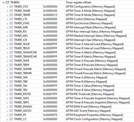
你可以截取寄存器 broswer 中所有 timer4寄存器的屏幕截图吗?
您是否已在 LaunchPad 上尝试过代码或者到目前为止它位于您的定制板上? 您是否在 LaunchPad 上遇到同样的问题?
尊敬的 Charles:
这是寄存器、我们还没有机会在 LaunchPad 上尝试。
谢谢、Doug
尊敬的 Doug:
您的计时器正在递增计数、但计数器的预加载值已经在0xFFFF。 在递增计数时、计时器应从0开始。 您可以将计数器预加载为0并重试吗? 或者、可以更改为 TIMER_CFG_B_CAP_COUNT (用于递减计数)而不是 TIMER_CFG_B_CAP_COUNT_UP。
尊敬的 Charles:
TIMER_TBVR 和 TIMER_TBV 都为0。 由于没有比较操作或任何触发事件、因此不使用 TIMER_TBMATCHR 寄存器。 我可以看到所有的定时器配置寄存器值都是正确的。
???
仅供参考、我确实验证了脉冲流将流向正确的引脚128、D7。
谢谢、Doug
尊敬的 Doug:
我创建一个简单示例。 我将 GPIO GN0切换100次并进入 PL5引脚、该引脚由 Timer0 TimerB 捕获、我可以正确地捕获100个负边沿。 请查看是否可以在电路板上复制并适应 Timer4。
//**************************************************************************** // // The variable g_ui32SysClock contains the system clock frequency in Hz. // //**************************************************************************** uint32_t g_ui32SysClock; //***************************************************************************** // // The error routine that is called if the driver library encounters an error. // //***************************************************************************** #ifdef DEBUG void __error__(char *pcFilename, uint32_t ui32Line) { } #endif //***************************************************************************** // // The interrupt handler for the Timer 0A interrupt. // //***************************************************************************** void Timer0AIntHandler(void) { // // Clear the timer interrupt. // MAP_TimerIntClear(TIMER0_BASE, TIMER_CAPA_EVENT); } //***************************************************************************** // // The interrupt handler for the Timer 0B interrupt. // //***************************************************************************** void Timer0BIntHandler(void) { // // Clear the timer interrupt. // MAP_TimerIntClear(TIMER0_BASE, TIMER_CAPB_EVENT); } //***************************************************************************** // // Configure the UART and its pins. This must be called before UARTprintf(). // //***************************************************************************** void ConfigureUART(void) { // // Enable the GPIO Peripheral used by the UART. // MAP_SysCtlPeripheralEnable(SYSCTL_PERIPH_GPIOA); // // Enable UART0. // MAP_SysCtlPeripheralEnable(SYSCTL_PERIPH_UART0); // // Configure GPIO Pins for UART mode. // MAP_GPIOPinConfigure(GPIO_PA0_U0RX); MAP_GPIOPinConfigure(GPIO_PA1_U0TX); MAP_GPIOPinTypeUART(GPIO_PORTA_BASE, GPIO_PIN_0 | GPIO_PIN_1); // // Initialize the UART for console I/O. // UARTStdioConfig(0, 115200, g_ui32SysClock); } //***************************************************************************** // // Configure the system clock, UART, and setup Timer0 to be a Split Timer // which uses the 8-bit prescaler to create two 24-bit timers to measure signal // high periods based on rising and falling edge events on the Timer pins PL4 // and PL5. The measurement results will be output on UART0 to the Virtual // Serial Port. // //***************************************************************************** int main(void) { uint32_t ui32EdgeCount = 0; uint32_t i; // // Run from the PLL at 120 MHz. // Note: SYSCTL_CFG_VCO_240 is a new setting provided in TivaWare 2.2.x and // later to better reflect the actual VCO speed due to SYSCTL#22. // g_ui32SysClock = MAP_SysCtlClockFreqSet((SYSCTL_XTAL_25MHZ | SYSCTL_OSC_MAIN | SYSCTL_USE_PLL | SYSCTL_CFG_VCO_240), 120000000); // // Enable the peripherals used by this example. // MAP_SysCtlPeripheralEnable(SYSCTL_PERIPH_TIMER0); MAP_SysCtlPeripheralEnable(SYSCTL_PERIPH_GPIOL); // // Configure the GPIO to be CCP pins for the Timer peripheral. // MAP_GPIOPinConfigure(GPIO_PL5_T0CCP1); // // Configure the GPIO for the Timer peripheral. // MAP_GPIOPinTypeTimer(GPIO_PORTL_BASE, GPIO_PIN_5); // // Initialize the UART and write initial status. // ConfigureUART(); UARTprintf("Edge Capture Example for measuring the high period of an" "input signal.\n"); UARTprintf("Input a square wave onto pin PL4 and PL5 of the " "EK-TM4C1294XL.\n"); // // Initialize Timers A and B to both run as periodic up-count edge capture // timers. This will split the 32-bit timer into two 16-bit timers. // MAP_TimerConfigure(TIMER0_BASE, (TIMER_CFG_SPLIT_PAIR | TIMER_CFG_B_PERIODIC | TIMER_CFG_B_CAP_COUNT_UP)); // // To use the timer in Edge Time mode, it must be preloaded with initial // values. If the prescaler is used, then it must be preloaded as well. // Since we want to use all 24-bits for both timers it will be loaded with // the maximum of 0xFFFF for the 16-bit wide split timers, and 0xFF to add // the additional 8-bits to the split timers with the prescaler. // MAP_TimerLoadSet(TIMER0_BASE, TIMER_BOTH, 0xFFFF); MAP_TimerPrescaleSet(TIMER0_BASE, TIMER_BOTH, 0xFF); // // configure Timer B // to trigger on a Negative Edge. // MAP_TimerControlEvent(TIMER0_BASE, TIMER_B, TIMER_EVENT_NEG_EDGE); // // Enable the Timer B interrupts for Capture Events. // MAP_TimerIntEnable(TIMER0_BASE, TIMER_CAPB_EVENT); // // Enable processor interrupts. // MAP_IntMasterEnable(); // // Enable and wait for the port to be ready for access // SysCtlPeripheralEnable(SYSCTL_PERIPH_GPION); while(!SysCtlPeripheralReady(SYSCTL_PERIPH_GPION)) { } // // Configure the GPIO port for the LED operation. // GPIOPinTypeGPIOOutput(GPIO_PORTN_BASE, GPIO_PIN_0); // // Enable both Timer Timer B to begin the application. // MAP_TimerEnable(TIMER0_BASE, TIMER_B); // // Loop Forever // for (i=0;i<100;i++) { // // Turn on the LED // GPIOPinWrite(GPIO_PORTN_BASE, GPIO_PIN_0, GPIO_PIN_0); // // Turn on the LED // GPIOPinWrite(GPIO_PORTN_BASE, GPIO_PIN_0, 0); } ui32EdgeCount = TimerValueGet(TIMER0_BASE, TIMER_B); if (ui32EdgeCount == 100){ UARTprintf("pass"); } else { UARTprintf("Fail"); } while (1); }
尊敬的 Charles:
我发现了问题,我看了一个时候,但我看不到它,但没有哭出来,当我看到它。 我首先尝试将 D7设置为中断、但没有脉冲通过。 然后、我将其配置为输出、并尝试发送没有效果的脉冲。 然后我的大脑的灯泡又熄灭了,我意识到我误读了有关解锁它的部分; D7不能配置为任何东西,但 NMI 没有首先解锁它。 一旦我做了、我的原始代码就运行正常。
谢谢、Doug