请注意,本文内容源自机器翻译,可能存在语法或其它翻译错误,仅供参考。如需获取准确内容,请参阅链接中的英语原文或自行翻译。
器件型号:TMS320F280049 尊敬的香榭丽舍
我向我们的客户提出这一问题。
请您帮助澄清一下吗?
我们使用下面的输入。
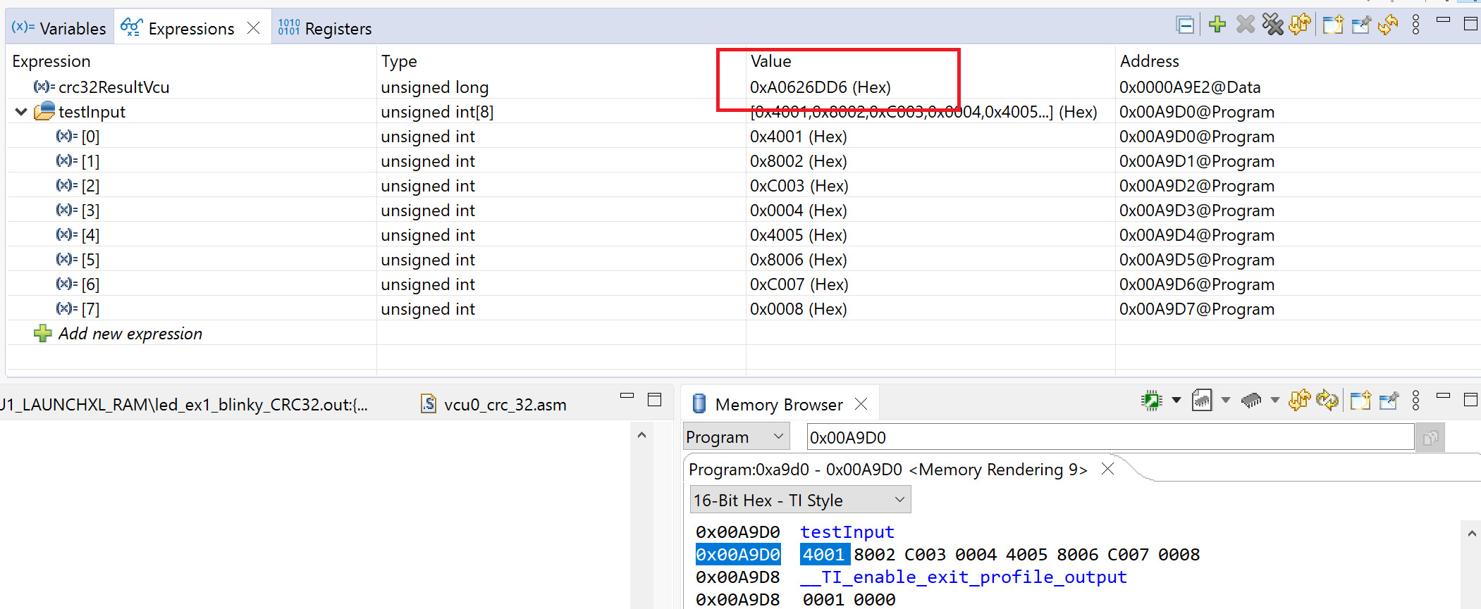
静态常量 uint16 testInput[CRC_TEST_PACKET_LEN]={
0x4001、0x8002、0xC003、0x0004、0x4005、 0x8006、0xC007、0x0008
};
MAIN ()
{
(笑声)
//计算 CRC-32示例
crc32ResultVcu = getCRC32_VCU (0xFFFFFFFF、(uint16*) testInput、
(crc_parity) crc_parity 偶校验、crc_test_packet_bytes);
(笑声)
}
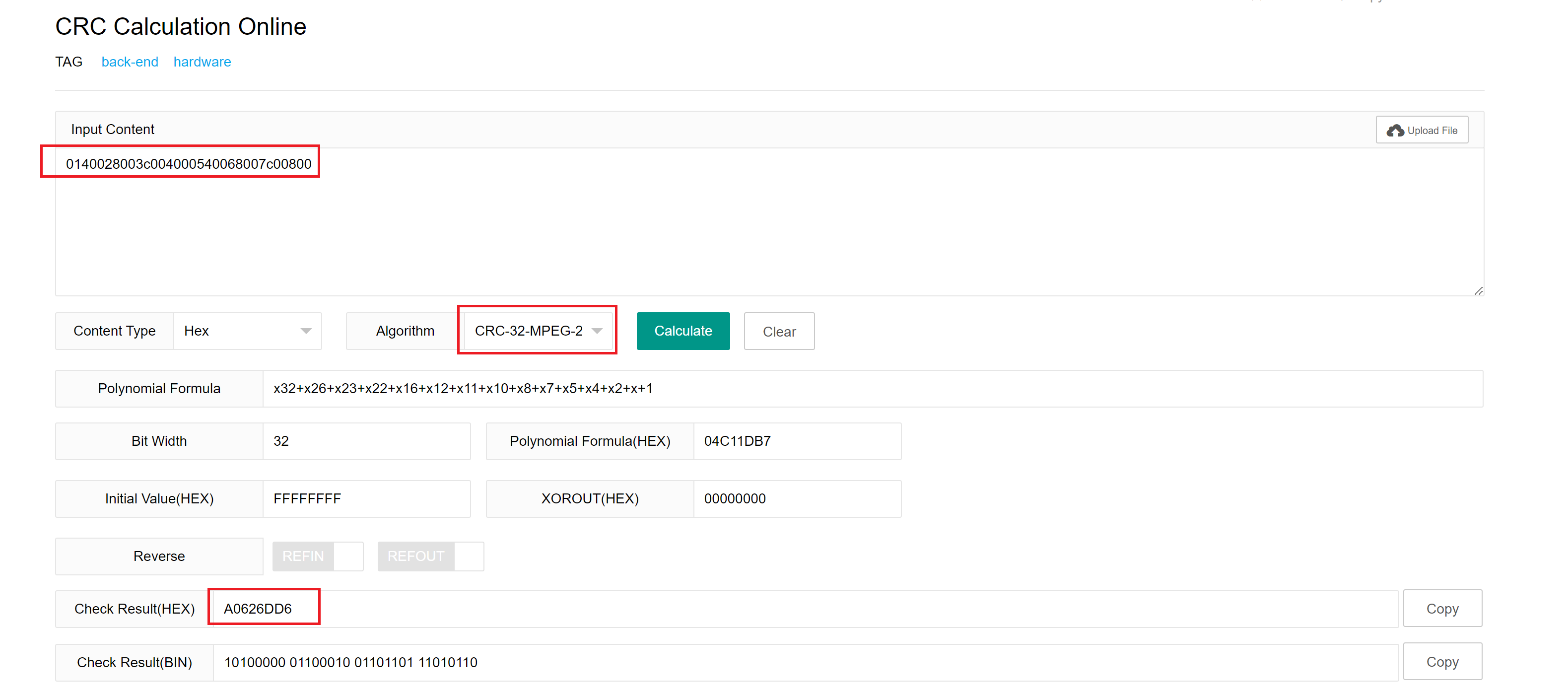
结果为0xA0626DD6、如下所示。
在线计算器
https://www.lddgo.net/en/encrypt/crc
结果 为0x9B37AF70。
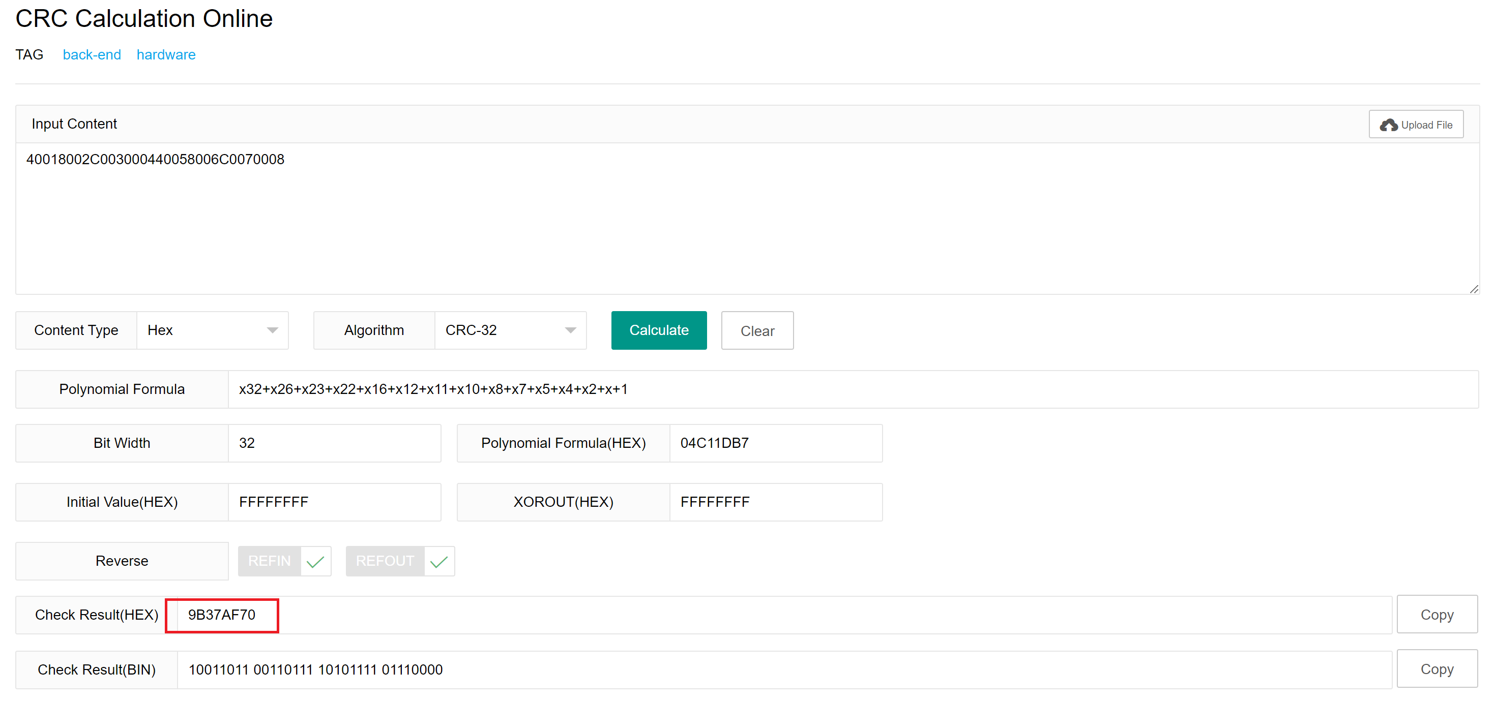
我们尝试了不同的在线工具、它们是相同的、但结果与我们的 VCU0 CRC 不同。
请您帮助澄清一下吗?
我们使用的代码包含在这里-使用 TI LED 闪烁示例和此 CRC32计算。
//
// Included Files
//
#include "driverlib.h"
#include "device.h"
#include "vcu0_crc.h"


//! Test Packet Length in number of words
#define CRC_TEST_PACKET_LEN     8
//! Test Packet Length in number of BYTES
#define CRC_TEST_PACKET_BYTES   (CRC_TEST_PACKET_LEN << 1)


static const uint16 testInput[CRC_TEST_PACKET_LEN] = {
    0x4001, 0x8002, 0xC003, 0x0004, 0x4005, 0x8006, 0xC007, 0x0008
};

volatile uint32_t crc32ResultVcu;


//
// Main
//
void main(void)
{


    //
    // Initialize device clock and peripherals
    //
    Device_init();

    //
    // Initialize GPIO and configure the GPIO pin as a push-pull output
    //
    Device_initGPIO();
    GPIO_setPadConfig(DEVICE_GPIO_PIN_LED1, GPIO_PIN_TYPE_STD);
    GPIO_setDirectionMode(DEVICE_GPIO_PIN_LED1, GPIO_DIR_MODE_OUT);

    //
    // Initialize PIE and clear PIE registers. Disables CPU interrupts.
    //
    Interrupt_initModule();

    //
    // Initialize the PIE vector table with pointers to the shell Interrupt
    // Service Routines (ISR).
    //
    Interrupt_initVectorTable();

    //
    // Enable Global Interrupt (INTM) and realtime interrupt (DBGM)
    //
    EINT;
    ERTM;

    // Calculate CRC-32 example
    crc32ResultVcu   = getCRC32_vcu(0xFFFFFFFF, (uint16*)testInput,
            (CRC_parity_e)CRC_parity_even, CRC_TEST_PACKET_BYTES);


    //
    // Loop Forever
    //
    for(;;)
    {
        //
        // Turn on LED
        //
        GPIO_writePin(DEVICE_GPIO_PIN_LED1, 0);

        //
        // Delay for a bit.
        //
        DEVICE_DELAY_US(500000);

        //
        // Turn off LED
        //
        GPIO_writePin(DEVICE_GPIO_PIN_LED1, 1);

        //
        // Delay for a bit.
        //
        DEVICE_DELAY_US(500000);
    }
}