请注意,本文内容源自机器翻译,可能存在语法或其它翻译错误,仅供参考。如需获取准确内容,请参阅链接中的英语原文或自行翻译。
器件型号:TMS320F28384D 尊敬的团队:
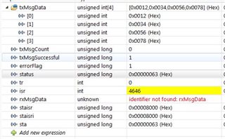
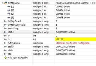
我正在控制器中运行上述程序。接收操作正常工作、当我尝试将其用作发送时、其错误标志为1、传输未发生。
CAN_Get 状态值 为0x00000063。我已附加代码和表达式映像。请就此提供帮助。! 有时可变 ISR 变为负。
提前感谢!
//#############################################################################
//
// FILE:   can_ex5_transmit_receive.c
//
// TITLE:   CAN Configuration for Transmit and Receive.
//
//! \addtogroup driver_example_list
//! <h1> CAN Transmit and Receive Configurations </h1>
//!
//! This example shows the basic setup of CAN in order to transmit or receive
//! messages on the CAN bus with a specific Message ID. The CAN Controller is
//! configured according to the selection of the define.
//!
//! When the TRANSMIT define is selected, the CAN Controller acts as a
//! Transmitter and sends data to the second CAN Controller connected
//! externally.If TRANMSIT is not defined the CAN Controller acts as a Receiver
//! and waits for message to be transmitted by the External CAN Controller.
//! Please refer to the appnote Programming Examples and Debug Strategies
//! for the DCAN Module (www.ti.com/lit/SPRACE5) for useful information
//! about this example
//!
//! \note CAN modules on the device need to be connected to via CAN
//!       transceivers.
//!
//! \b Hardware \b Required \n
//!  - A C2000 board with CAN transceiver.
//!
//! \b External \b Connections \n
//!  - ControlCARD CANA is on DEVICE_GPIO_PIN_CANTXA (CANTXA)
//!  - and DEVICE_GPIO_PIN_CANRXA (CANRXA)
//!
//! \b Watch \b Variables \b Transmit \Configuration \n
//!  - MSGCOUNT   - Adjust to set the number of messages
//!  - txMsgCount - A counter for the number of messages sent
//!  - txMsgData  - An array with the data being sent
//!  - errorFlag  - A flag that indicates an error has occurred
//!  - rxMsgCount - Has the initial value as No. of Messages to be received
//!                 and decrements with each message.
//!
//
//#############################################################################

//
// Included Files
//
#include "driverlib.h"
#include "device.h"

//
// Comment to Make the CAN Controller work as a Receiver.
//
#define TRANSMIT

//
// Defines
//
#ifdef TRANSMIT
#define TX_MSG_OBJ_ID    1
#else
#define RX_MSG_OBJ_ID    1
#endif
#define MSG_DATA_LENGTH  4
#define MSGCOUNT        10
//#include "canstr.h"

//!!!!!!!!!!!!!!!!!!!!!!!!!!!!!!!!!!!!!
/*
#define IPC_CMD_READ_MEM   0x1001
#define IPC_CMD_RESP       0x2001

#define TEST_PASS          0x5555
#define TEST_FAIL          0xAAAA

*/
#define PACKET_LENGTH 10
#pragma DATA_SECTION(packetData, "MSGRAM_CPU_TO_CM")
uint8_t packetData[PACKET_LENGTH];
uint32_t pass;
uint32_t readData[10];
uint32_t status;
uint8_t MsgCnt;
int tr;
int isr;
unsigned long staisr;
unsigned long staisri;
unsigned long sta;

//!!!!!!!!!!!!!!!!!!!!!!!!!!!!!!!!!!!!!!!!

//
// Globals
//
#ifdef TRANSMIT
volatile uint32_t txMsgCount = 0;
uint32_t txMsgSuccessful  = 1;
uint16_t txMsgData[4];
#else
volatile uint32_t rxMsgCount = MSGCOUNT;
uint16_t rxMsgData[8];

#endif
volatile unsigned long i;
volatile uint32_t errorFlag = 0;

//!!!!!!!!!!!!!!!!!!!!!!!!!!

IPC_MessageQueue_t messageQueue;
IPC_Message_t      TxMsg, RxMsg;
uint8_t TX;

//!!!!!!!!!!!!!!!!!!!!!!!!

//
// Function Prototypes
//
__interrupt void canaISR(void);

//
// Main
//
void main(void)
{


    // Initialize device clock and peripherals
    //
    Device_init();

    //
    // Initialize GPIO and configure GPIO pins for CANTX/CANRX
    // on module A.
    //
    Device_initGPIO();

    GPIO_setPinConfig(DEVICE_GPIO_CFG_CANRXA);
    GPIO_setPinConfig(DEVICE_GPIO_CFG_CANTXA);

    /////////////////////////////////////////////

    /////////////////////////////////////////////
    //
    // Allocated shared peripheral to C28x
    //
    SysCtl_allocateSharedPeripheral(SYSCTL_PALLOCATE_CAN_A,0x0U);
    SysCtl_allocateSharedPeripheral(SYSCTL_PALLOCATE_CAN_B,0x0U);

    //
    // Initialize the CAN controllers
    //
    CAN_initModule(CANA_BASE);

    //
    // Set up the CAN bus bit rate to 500kHz for each module
    // Refer to the Driver Library User Guide for information on how to set
    // tighter timing control. Additionally, consult the device data sheet
    // for more information about the CAN module clocking.
    //
    CAN_setBitRate(CANA_BASE, DEVICE_SYSCLK_FREQ, 500000, 20);

    //
    // Enable interrupts on the CAN A peripheral.
    //


    CAN_enableInterrupt (CANA_BASE, CAN_INT_IE0 | CAN_INT_ERROR |
                        CAN_INT_STATUS);

    //
    // Initialize PIE and clear PIE registers. Disables CPU interrupts.
    //
    Interrupt_initModule();

    //
    // Initialize the PIE vector table with pointers to the shell Interrupt
    // Service Routines (ISR).
    //
    Interrupt_initVectorTable();

    //
    // Enable Global Interrupt (INTM) and realtime interrupt (DBGM)
    //
    EINT;
    ERTM;

    //
    // Interrupts that are used in this example are re-mapped to
    // ISR functions found within this file.
    // This registers the interrupt handler in PIE vector table.
    //
    Interrupt_register(INT_CANA0,&canaISR);

    //
    // Enable the CAN-A interrupt signal
    //
    Interrupt_enable(INT_CANA0);

    CAN_enableGlobalInterrupt(CANA_BASE, CAN_GLOBAL_INT_CANINT0);

#ifdef TRANSMIT
    //
    // Initialize the transmit message object used for sending CAN messages.
    // Message Object Parameters:
    //      CAN Module: A
    //      Message Object ID Number: 1
    //      Message Identifier: 0x15555555
    //      Message Frame: Extended
    //      Message Type: Transmit
    //      Message ID Mask: 0x0
    //      Message Object Flags: None
    //      Message Data Length: 4 Bytes
    //
    CAN_setupMessageObject(CANA_BASE, TX_MSG_OBJ_ID, 0x00000001,    //0x15555555
                           CAN_MSG_FRAME_STD, CAN_MSG_OBJ_TYPE_TX, 0, //EXT
                           CAN_MSG_OBJ_TX_INT_ENABLE, MSG_DATA_LENGTH);
    //
    // Initialize the transmit message object data buffer to be sent
    //
    txMsgData[0] = 0x12;
    txMsgData[1] = 0x34;
    txMsgData[2] = 0x56;
    txMsgData[3] = 0x78;
#else
    //
    // Initialize the receive message object used for receiving CAN messages.
    // Message Object Parameters:
    //      CAN Module: A
    //      Message Object ID Number: 1
    //      Message Identifier: 0x15555555
    //      Message Frame: Extended
    //      Message Type: Receive
    //      Message ID Mask: 0x0
    //      Message Object Flags: Receive Interrupt
    //      Message Data Length: 4 Bytes (Note that DLC field is a "don't care"
    //      for a Receive mailbox
    //
    CAN_setupMessageObject(CANA_BASE, RX_MSG_OBJ_ID, 0x15555555,
                           CAN_MSG_FRAME_EXT, CAN_MSG_OBJ_TYPE_RX, 0,
                           CAN_MSG_OBJ_RX_INT_ENABLE, MSG_DATA_LENGTH);
#endif

    //
    // Start CAN module A operations
    //
    CAN_startModule(CANA_BASE);

#ifdef TRANSMIT


    //
    // Transmit messages from CAN-A.
    //
    for(i = 0; i < MSGCOUNT; i++)
    {
        //
        // Check the error flag to see if errors occurred
        //

        if(errorFlag)
        {
            asm("   ESTOP0");
        }

        //
        // Transmit the message.
        //

        CAN_sendMessage(CANA_BASE, TX_MSG_OBJ_ID, MSG_DATA_LENGTH,
                        txMsgData);

        //
        // Delay 0.25 second before continuing
        //
        DEVICE_DELAY_US(250000);

       while(txMsgSuccessful);


        //
        // Increment the value in the transmitted message data.
        //
        txMsgData[0] += 0x01;
        txMsgData[1] += 0x01;
        txMsgData[2] += 0x01;
        txMsgData[3] += 0x01;

        //
        // Reset data if exceeds a byte
        //
        if(txMsgData[0] > 0xFF)
        {
            txMsgData[0] = 0;
        }
        if(txMsgData[1] > 0xFF)
        {
            txMsgData[1] = 0;
        }
        if(txMsgData[2] > 0xFF)
        {
            txMsgData[2] = 0;
        }
        if(txMsgData[3] > 0xFF)
        {
            txMsgData[3] = 0;
        }

        //
        // Update the flag for next message.
        //
        txMsgSuccessful  = 1;
  }
#else
    //
    // Loop to keep receiving data from another CAN Controller.
    //
    while(rxMsgCount)
    {
        MsgCnt++;
    }

#endif

    //
    // Stop application after completion.
    //
   asm("   ESTOP0");

}

//
// CAN A ISR - The interrupt service routine called when a CAN interrupt is
//             triggered on CAN module A.
//
__interrupt void
canaISR(void)
{

isr++;
    //
    // Read the CAN-B interrupt status to find the cause of the interrupt
    //
    status = CAN_getInterruptCause(CANA_BASE);
    staisr = status;


    //
    // If the cause is a controller status interrupt, then get the status
    //

    if(status == CAN_INT_INT0ID_STATUS)
    {
        staisri=status;
        //
        // Read the controller status.  This will return a field of status
        // error bits that can indicate various errors.  Error processing
        // is not done in this example for simplicity.  Refer to the
        // API documentation for details about the error status bits.
        // The act of reading this status will clear the interrupt.
        //
        status = CAN_getStatus(CANA_BASE);
        sta=status;
        //
        // Check to see if an error occurred.

        //

#ifdef TRANSMIT
        if(((status  & ~(CAN_STATUS_TXOK)) != CAN_STATUS_LEC_MSK) &&
           ((status  & ~(CAN_STATUS_TXOK)) != CAN_STATUS_LEC_NONE))
#else
        if(((status  & ~(CAN_STATUS_RXOK)) != CAN_STATUS_LEC_MSK) &&
           ((status  & ~(CAN_STATUS_RXOK)) != CAN_STATUS_LEC_NONE))
#endif
        {
            //
            // Set a flag to indicate some errors may have occurred.
            //
           errorFlag = 1;
        }

    }

#ifdef TRANSMIT
    else if(status == TX_MSG_OBJ_ID) //else
    {
        tr++;
        //
        // Getting to this point means that the TX interrupt occurred on
        // message object 1, and the message TX is complete.  Clear the
        // message object interrupt.
        //
        CAN_clearInterruptStatus(CANA_BASE, TX_MSG_OBJ_ID);

        //
        // Increment a counter to keep track of how many messages have been
        // transmitted. In a real application this could be used to set flags to
        // indicate when a message is transmitted.
        //
        txMsgCount++;

        //
        // Since the message was transmitted, clear any error flags.
        //
        errorFlag = 0;

        //
        // Clear the message transmitted successful Flag.
        //
        txMsgSuccessful  = 0;//0
    }
#else
    else if(status == RX_MSG_OBJ_ID)
    {
        //
        // Get the received message
        //
        CAN_readMessage(CANA_BASE, RX_MSG_OBJ_ID, rxMsgData);

        //
        // Getting to this point means that the RX interrupt occurred on
        // message object 1, and the message RX is complete.  Clear the
        // message object interrupt.
        //
        CAN_clearInterruptStatus(CANA_BASE, RX_MSG_OBJ_ID);

        //
        // Decrement the counter after a message has been received.
        //
        rxMsgCount--;

        //
        // Since the message was received, clear any error flags.
        //
        errorFlag = 0;
    }
#endif
    //
    // If something unexpected caused the interrupt, this would handle it.
    //
    else
    {
        //
        // Spurious interrupt handling can go here.
        //
    }

    //
    // Clear the global interrupt flag for the CAN interrupt line
    //
    CAN_clearGlobalInterruptStatus(CANA_BASE, CAN_GLOBAL_INT_CANINT0);

    //
    // Acknowledge this interrupt located in group 9
    //
    Interrupt_clearACKGroup(INTERRUPT_ACK_GROUP9);
    //status = 0;
}

//
// End of File
//