This thread has been locked.

If you have a related question, please click the "Ask a related question" button in the top right corner. The newly created question will be automatically linked to this question.

[参考译文] TMS320F280049C:使用 PWM 同步 SDFM 时的问题

Guru**** 1626620 points
Other Parts Discussed in Thread: C2000WARE, LAUNCHXL-F280049C, AMC1306EVM
请注意,本文内容源自机器翻译,可能存在语法或其它翻译错误,仅供参考。如需获取准确内容,请参阅链接中的英语原文或自行翻译。

https://e2e.ti.com/support/microcontrollers/c2000-microcontrollers-group/c2000/f/c2000-microcontrollers-forum/1008118/tms320f280049c-the-problems-when-using-pwm-to-synchronize-sdfm

器件型号:TMS320F280049C
主题中讨论的其他器件:C2000WARELAUNCHXL-F280049CAMC1306EVM

你(们)好

我已将 \\ti\c2000Ware_3_02_00_00\driverlib\f28004x\examples\sdfm 下的 sdfm_ex5_filter_sync_fifo_cpuread.c 更改为将 PWM8用于同步信号、将 PWM1用于 SDFM 时钟。
本计划有以下一些问题:
当我使用 SDFM_enableWaitForSync (第212行)让 SDFM 等待 PWM SOCA 信号时、程序无法进入 sdfmFIFO1ISR。
2.当我不使用 SDFM_enableWaitForSync 时、程序会进入 sdfmFIFO1ISR、但进入的时间不合理:
我设置不同的 FIFO_INT_NUM 值、如果 FIFO_INT_NUM 增大、我假设转换时间(PWM8.TBCTR)应更大、
但我不遵循此规则的时间、请参阅以下数据(PWM1提供10MHz 时钟):
FIFO_INT_NUM 第2次运行     
  3.              6815.     7075
  4.              6753     6593
  5.              6793     6665
  9.              6675     6493

此处列出的代码供您查看:

//###########################################################################
//
// FILE:   sdfm_ex5_filter_sync_fifo_cpuread.c
//
// TITLE:  SDFM Type 1 Filter FIFO Example.
//
//! \addtogroup driver_example_list
//! <h1> SDFM Type 1 Filter FIFO </h1>
//!
//! This example configures SDFM1 filter to demonstrate data read through
//! CPU in FIFO & non-FIFO mode. Data filter is configured in mode 0
//! to select SINC3 filter with OSR of 256. Filter output is configured
//! for 16-bit format and data shift of 10 is used.
//!
//! This example demonstrates the FIFO usage if enabled. FIFO length is set
//! at 16 and data ready interrupt is configured to be triggered when FIFO is
//! full. In this example, SDFM filter data is read by CPU in SDFM Data Ready
//! ISR routine.
//!
//! \b External \b Connections \n
//!    Connect Sigma-Delta streams to (SD-D1, SD-C1 to SD-D4,SD-C4)
//!    on GPIO24-GPIO31
//!
//! \b Watch \b Variables \n
//! -  \b filter1Result - Output of filter 1
//!
//
//###########################################################################
// $TI Release: F28004x Support Library v1.09.00.00 $
// $Release Date: Thu Mar 19 07:26:52 IST 2020 $
// $Copyright:
// Copyright (C) 2020 Texas Instruments Incorporated - http://www.ti.com/
//
// Redistribution and use in source and binary forms, with or without 
// modification, are permitted provided that the following conditions 
// are met:
// 
//   Redistributions of source code must retain the above copyright 
//   notice, this list of conditions and the following disclaimer.
// 
//   Redistributions in binary form must reproduce the above copyright
//   notice, this list of conditions and the following disclaimer in the 
//   documentation and/or other materials provided with the   
//   distribution.
// 
//   Neither the name of Texas Instruments Incorporated nor the names of
//   its contributors may be used to endorse or promote products derived
//   from this software without specific prior written permission.
// 
// THIS SOFTWARE IS PROVIDED BY THE COPYRIGHT HOLDERS AND CONTRIBUTORS 
// "AS IS" AND ANY EXPRESS OR IMPLIED WARRANTIES, INCLUDING, BUT NOT 
// LIMITED TO, THE IMPLIED WARRANTIES OF MERCHANTABILITY AND FITNESS FOR
// A PARTICULAR PURPOSE ARE DISCLAIMED. IN NO EVENT SHALL THE COPYRIGHT 
// OWNER OR CONTRIBUTORS BE LIABLE FOR ANY DIRECT, INDIRECT, INCIDENTAL, 
// SPECIAL, EXEMPLARY, OR CONSEQUENTIAL DAMAGES (INCLUDING, BUT NOT 
// LIMITED TO, PROCUREMENT OF SUBSTITUTE GOODS OR SERVICES; LOSS OF USE,
// DATA, OR PROFITS; OR BUSINESS INTERRUPTION) HOWEVER CAUSED AND ON ANY
// THEORY OF LIABILITY, WHETHER IN CONTRACT, STRICT LIABILITY, OR TORT 
// (INCLUDING NEGLIGENCE OR OTHERWISE) ARISING IN ANY WAY OUT OF THE USE 
// OF THIS SOFTWARE, EVEN IF ADVISED OF THE POSSIBILITY OF SUCH DAMAGE.
// $
//###########################################################################

//
// Included Files
//
#include "driverlib.h"
#include "device.h"
#include <stdio.h>

#define JIAKAI
//
// Defines
//
#define MAX_SAMPLES               1024
#define FIFO_INT_NUM              9U
#define SDFM_FILTER_ENABLE 0x2U

//
// Macro to enable FIFO mode. Make it zero to disable
// FIFO mode.
//
#define ENABLE_FIFO               1

//
// Globals
//
int16_t  filter1Result[MAX_SAMPLES];
#pragma DATA_SECTION(filter1Result, "Filter1_RegsFile");

//
// Function Prototypes
//
void configureSDFMPins(void);
void initEPWM(uint32_t epwmInstance);
//
// ISRs
//
__interrupt void sdfmFIFO1ISR(void);
__interrupt void sdfm1ErrorISR(void);

//
// Main
//
void main(void)
{
    //
    // Initialize device clock and peripherals
    //
    Device_init();

    //
    // Setup GPIO by disabling pin locks and enabling pullups
    //
    Device_initGPIO();

    //
    // Initialize PIE and clear PIE registers. Disables CPU interrupts.
    //
    Interrupt_initModule();

    //
    // Initialize the PIE vector table with pointers to the shell Interrupt
    // Service Routines (ISR).
    //
    Interrupt_initVectorTable();

    //
    // Interrupts that are used in this example are re-mapped to
    // ISR functions found within this file.
    //
    Interrupt_clearACKGroup(INTERRUPT_ACK_GROUP5);
    Interrupt_register(INT_SDFM1DR1, sdfmFIFO1ISR);
    Interrupt_register(INT_SDFM1, sdfm1ErrorISR);

    //
    // Enable SDFM1 interrupts(Data Ready & Error interrupts)
    //
    Interrupt_enableMaster();
    Interrupt_enable(INT_SDFM1DR1);
    Interrupt_enable(INT_SDFM1);

    initEPWM(EPWM8_BASE);

    //
    // Configure GPIO pins as SDFM pins
    //
    configureSDFMPins();

    //
    // Input Control Unit
    //
    // Configure Input Control Unit: Modulator Clock rate = Modulator data rate
    //
    SDFM_setupModulatorClock(SDFM1_BASE, SDFM_FILTER_1,
                             SDFM_MODULATOR_CLK_EQUAL_DATA_RATE);

    //
    // Data Filter Unit
    //

    // Configure Data Filter Unit - filter type, OSR value and
    // enable / disable data filter
    //
    SDFM_configDataFilter(SDFM1_BASE, (SDFM_FILTER_1 | SDFM_FILTER_SINC_3 |
           SDFM_SET_OSR(256)), (SDFM_DATA_FORMAT_16_BIT | SDFM_FILTER_ENABLE |
           SDFM_SHIFT_VALUE(0x000A)));

#if (ENABLE_FIFO)
        //
        // Set data ready interrupt source as fifo interrupt
        //
        SDFM_setDataReadyInterruptSource(SDFM1_BASE, SDFM_FILTER_1,
                                         SDFM_DATA_READY_SOURCE_FIFO);

        //
        // Enable FIFO and set the FIFO interrupt level
        //
        SDFM_enableFIFOBuffer(SDFM1_BASE, SDFM_FILTER_1);

        SDFM_setFIFOInterruptLevel(SDFM1_BASE, SDFM_FILTER_1, FIFO_INT_NUM);

        SDFM_enableInterrupt(SDFM1_BASE, SDFM_FILTER_1,
                         (SDFM_FIFO_INTERRUPT | SDFM_FIFO_OVERFLOW_INTERRUPT));
#else
        //
        // Set data ready interrupt source as fifo interrupt
        //
        SDFM_setDataReadyInterruptSource(SDFM1_BASE, SDFM_FILTER_1,
                                         SDFM_DATA_READY_SOURCE_DIRECT);

        SDFM_enableInterrupt(SDFM1_BASE, SDFM_FILTER_1,
                             SDFM_DATA_FILTER_ACKNOWLEDGE_INTERRUPT);
#endif


    //
    // Enable Master filter bit: Unless this bit is set none of the filter
    // modules can be enabled. All the filter modules are synchronized when
    // master filter bit is enabled after individual filter modules are enabled.
    //
    SDFM_enableMasterFilter(SDFM1_BASE);

    //
    // Use PWM8.CMPA signals to synchronize the filters.
    //
#if (0)
    SDFM_disableExternalReset(SDFM1_BASE, SDFM_FILTER_1);
#else
    SDFM_enableExternalReset(SDFM1_BASE, SDFM_FILTER_1);
    SDFM_setPWMSyncSource(SDFM1_BASE, SDFM_FILTER_1, SDFM_SYNC_PWM8_SOCA);
//    SDFM_enableWaitForSync(SDFM1_BASE, SDFM_FILTER_1);
#endif

    //
    // Enable modulator failure interrupt, disable threshold interrupts
    //
    SDFM_enableInterrupt(SDFM1_BASE, SDFM_FILTER_1,
                         SDFM_MODULATOR_FAILURE_INTERRUPT);

    SDFM_disableInterrupt(SDFM1_BASE, SDFM_FILTER_1,
                          (SDFM_HIGH_LEVEL_THRESHOLD_INTERRUPT |
                           SDFM_LOW_LEVEL_THRESHOLD_INTERRUPT));

    //
    // Enable master interrupt so that any of the filter interrupts can trigger
    // by SDFM interrupt to CPU
    //
    SDFM_enableMasterInterrupt(SDFM1_BASE);

    //
    // Enable Global Interrupt (INTM) and realtime interrupt (DBGM)
    //
    EINT;
    ERTM;

    //
    // Wait for an interrupt
    //
    while(1);
}

//
// sdfm1ErrorISR - SDFM1 Error ISR
//
__interrupt void sdfm1ErrorISR(void)
{
    //
    // Clear SDFM flag register (SDIFLG)
    //
    SDFM_clearInterruptFlag(SDFM1_BASE, SDFM_MASTER_INTERRUPT_FLAG |
                            0xFFFF);

    //
    // Acknowledge this interrupt to receive more interrupts from group 5
    //
    Interrupt_clearACKGroup(INTERRUPT_ACK_GROUP5);
}

#define PWM_TBCTR(_p)       *((uint16_t *)(0x3F04 + 0x100 * (_p)))
int index = 0;
uint16_t tmBuf[100];

//
// sdfmFIFO1ISR - SDFM FIFO1 ISR
//
__interrupt void sdfmFIFO1ISR(void)
{
    uint16_t i;
    static uint16_t loopCounter1 = 0;

#if (0)
    SDFM_setOutputDataFormat(SDFM1_BASE, SDFM_FILTER_1,
                             SDFM_DATA_FORMAT_16_BIT);
#endif

    //
    // Read SDFM flag register (SDIFLG)
    //
    if(loopCounter1 >= MAX_SAMPLES)
    {
        ESTOP0;
    }
    else if(SDFM_getFIFOISRStatus(SDFM1_BASE, SDFM_FILTER_1) == 0x1U)
    {
        tmBuf[index] = PWM_TBCTR(8); if (++index >= 100) index = 0;
        for(i = 0; i < FIFO_INT_NUM; i++)
        {
            filter1Result[loopCounter1++] =
                         (int16_t)(SDFM_getFIFOData(SDFM1_BASE,
                                                    SDFM_FILTER_1) >> 16U);
        }

    }
    else if(SDFM_getNewFilterDataStatus(SDFM1_BASE, SDFM_FILTER_1) == 0x1U)
    {
        filter1Result[loopCounter1++] =
               (int16_t)(SDFM_getFilterData(SDFM1_BASE, SDFM_FILTER_1) >> 16U);
    }

    //
    // Clear SDFM flag register (SDIFLG)
    //
    SDFM_clearInterruptFlag(SDFM1_BASE, SDFM_MASTER_INTERRUPT_FLAG |
                            SDFM_FILTER_1_FIFO_INTERRUPT_FLAG      |
                            SDFM_FILTER_1_NEW_DATA_FLAG            |
                            SDFM_FILTER_1_FIFO_OVERFLOW_FLAG);

    //
    // Acknowledge this interrupt to receive more interrupts from group 5
    //
    Interrupt_clearACKGroup(INTERRUPT_ACK_GROUP5);
}

//
// configureSDFMPins - Configure SDFM GPIOs
//
void configureSDFMPins(void)
{
    uint16_t pin;
#ifdef JIAKAI
    for(pin = 16; pin <= 17; pin++)
    {
//        GPIO_setDirectionMode(pin, GPIO_DIR_MODE_IN);
        GPIO_setMasterCore(pin, GPIO_CORE_CPU1);
        GPIO_setPadConfig(pin, GPIO_PIN_TYPE_STD);
        GPIO_setQualificationMode(pin, GPIO_QUAL_ASYNC);
    }
    GPIO_setPinConfig(GPIO_16_SD_D1);
    GPIO_setPinConfig(GPIO_17_SD_C1);
#else
    for(pin = 24; pin <= 31; pin++)
    {
        GPIO_setDirectionMode(pin, GPIO_DIR_MODE_IN);
        GPIO_setMasterCore(pin, GPIO_CORE_CPU1);
        GPIO_setPadConfig(pin, GPIO_PIN_TYPE_STD);
        GPIO_setQualificationMode(pin, GPIO_QUAL_ASYNC);
    }

    //
    // Configure GPIO16-GPIO31 as SDFM pins
    //
    GPIO_setPinConfig(GPIO_24_SD_D1);
    GPIO_setPinConfig(GPIO_25_SD_C1);
    GPIO_setPinConfig(GPIO_26_SD_D2);
    GPIO_setPinConfig(GPIO_27_SD_C2);
    GPIO_setPinConfig(GPIO_28_SD_D3);
    GPIO_setPinConfig(GPIO_29_SD_C3);
    GPIO_setPinConfig(GPIO_30_SD_D4);
    GPIO_setPinConfig(GPIO_31_SD_C4);
#endif
}


//
// initEPWM - Initialize specified EPWM settings
//
void initEPWM(uint32_t epwmInstance)
{
    //
    // Disable sync(Freeze clock to PWM as well)
    //
    SysCtl_disablePeripheral(SYSCTL_PERIPH_CLK_TBCLKSYNC);

    //
    // Setup TBCLK: Configure timer period = 801 TBCLKs, phase = 0 &
    // clear counter
    //
    EPWM_setTimeBasePeriod(epwmInstance, 0xFFFF);
    EPWM_setPhaseShift(epwmInstance, 0U);
    EPWM_setTimeBaseCounter(epwmInstance, 0U);

    //
    // Set CMPA value
    //
    EPWM_setCounterCompareValue(epwmInstance, EPWM_COUNTER_COMPARE_A, 200U);

    //
    // Setup counter mode
    //
    EPWM_setTimeBaseCounterMode(epwmInstance, EPWM_COUNTER_MODE_UP);
    EPWM_setClockPrescaler(epwmInstance,
                           EPWM_CLOCK_DIVIDER_1,
                           EPWM_HSCLOCK_DIVIDER_1);

    //
    // Set actions:
    // Toggle PWMxA on event A, up-count
    // Toggle PWMxB on event A, up-count
    //
    GPIO_setPadConfig(0, GPIO_PIN_TYPE_STD);
    GPIO_setPinConfig(GPIO_0_EPWM1A);
    GPIO_setPadConfig(1, GPIO_PIN_TYPE_STD);
    GPIO_setPinConfig(GPIO_1_EPWM1B);
    EPWM_setTimeBasePeriod(EPWM1_BASE, 4);     // PWM1 period: 0.1us
    EPWM_setTimeBaseCounterMode(EPWM1_BASE, EPWM_COUNTER_MODE_UP);
    EPWM_setClockPrescaler(EPWM1_BASE,
                           EPWM_CLOCK_DIVIDER_1,
                           EPWM_HSCLOCK_DIVIDER_1);
    EPWM_setActionQualifierAction(EPWM1_BASE,
                                  EPWM_AQ_OUTPUT_A,
                                  EPWM_AQ_OUTPUT_TOGGLE,
                                  EPWM_AQ_OUTPUT_ON_TIMEBASE_PERIOD);
//                                EPWM_AQ_OUTPUT_ON_TIMEBASE_UP_CMPA);
    EPWM_setActionQualifierAction(EPWM1_BASE,
                                  EPWM_AQ_OUTPUT_B,
                                  EPWM_AQ_OUTPUT_TOGGLE,
                                  EPWM_AQ_OUTPUT_ON_TIMEBASE_PERIOD);
//                                EPWM_AQ_OUTPUT_ON_TIMEBASE_UP_CMPB);

#ifndef JIAKAI
    //
    // Configure SOCA signal
    //
    //
    EPWM_setADCTriggerSource(EPWM1_BASE, EPWM_SOC_A, EPWM_SOC_TBCTR_U_CMPA);
    EPWM_setADCTriggerEventPrescale(EPWM1_BASE, EPWM_SOC_A, 1);
#endif

    //
    // Enable sync and clock to PWM
    //
    SysCtl_enablePeripheral(SYSCTL_PERIPH_CLK_TBCLKSYNC);
}

//
// End of file
//

有人能教我如何使用 PWM SOCA/B 同步 SDFM 吗?

谢谢、

Jiakai

  • 请注意,本文内容源自机器翻译,可能存在语法或其它翻译错误,仅供参考。如需获取准确内容,请参阅链接中的英语原文或自行翻译。

    您好、Jaikai、

    ePWM TBPRD (周期寄存器)的值应该高于 ePWM 计数器比较寄存器、这在代码中不是这样。 这不会生成所需的 ePWM 信号边沿、因此将无法为模块生成 SOC 信号。 请更新这些值。

    您可以在您的案例中更新时钟预分频器的值以调整这些值。

    谢谢、

    Aditya

  • 请注意,本文内容源自机器翻译,可能存在语法或其它翻译错误,仅供参考。如需获取准确内容,请参阅链接中的英语原文或自行翻译。

    您好、Aditya、

    EPWM8.CMPA 为0xC80000、我认为没关系、这意味着 EPWM8.CMPA=0xC8和 EPWM8.CMPAHR=0。

    谢谢、

    Jiakai

  • 请注意,本文内容源自机器翻译,可能存在语法或其它翻译错误,仅供参考。如需获取准确内容,请参阅链接中的英语原文或自行翻译。

    Jaikai、

    我也同意。 我要强调的一点是、TBPRD 值应高于 CMPA 值、在您的情况下不是如此->(TBPRD = 4)和(CMPA = 200)。 您可以尝试将 CMPA 寄存器更改为2以进行验证。

    如果您有示波器或任何其他方法来检查 ePWM 输出、我建议检查一次。

    谢谢、

    Aditya

  • 请注意,本文内容源自机器翻译,可能存在语法或其它翻译错误,仅供参考。如需获取准确内容,请参阅链接中的英语原文或自行翻译。

    您好、Aditya、

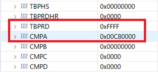
    在代码中、PWM8用于同步 SDFM、其对应的注册表值如下:

    您可能会使 PWM1和 PWM8混乱、因为我使用 PWM1来提供10MHz 时钟、因此 PWM1.TBPRD=4。

    谢谢、

    Jiakai

  • 请注意,本文内容源自机器翻译,可能存在语法或其它翻译错误,仅供参考。如需获取准确内容,请参阅链接中的英语原文或自行翻译。

    您好、Jaikai、

    很抱歉我错过了该部件。 感谢您的突出显示。 我目前正在对此进行研究。

    此外、我在示例代码中执行初始化之后提供的等待函数、该函数在您的示例代码中缺失。 您能否添加并在我返回给您时进行检查?

    while((HWREGH(pwmInstance + EPWM_O_TBCTR)) < 550);
    

    Aditya

  • 请注意,本文内容源自机器翻译,可能存在语法或其它翻译错误,仅供参考。如需获取准确内容,请参阅链接中的英语原文或自行翻译。

    您好、Aditya、

    我已将其添加到 main()函数中,如下所示:

    SDFM_DisableInterrupt (SDFM1_base、SDFM_FILTER_1、
    (SDFM_HIGH_LEVEL_THRESHOLD_INTERRUPT |
    SDFM_LOW_LEVEL_THRESHOLD_INTERRUPT));

    while (((HWREGH (EPWM8_BASE + EPWM_O_TBCTR))< 550);

    //
    //启用主中断,以便可以触发任何过滤器中断
    //通过 SDFM 中断到 CPU
    //
    SDFM_enableMasterInterrupt (SDFM1_base);

    多次运行代码、未找到差异。

    谢谢、

    Jiakai

  • 请注意,本文内容源自机器翻译,可能存在语法或其它翻译错误,仅供参考。如需获取准确内容,请参阅链接中的英语原文或自行翻译。

    Jaikai、

    请给我一些时间来思考这个问题。

    谢谢、

    Aditya

  • 请注意,本文内容源自机器翻译,可能存在语法或其它翻译错误,仅供参考。如需获取准确内容,请参阅链接中的英语原文或自行翻译。

    Aditya、  

    别着急,慢慢来。

    谢谢、

    Jiakai

  • 请注意,本文内容源自机器翻译,可能存在语法或其它翻译错误,仅供参考。如需获取准确内容,请参阅链接中的英语原文或自行翻译。

    您好、Jaikai、

    很抱歉耽误你的答复。 我看到您已禁用负责在代码中生成 SDSYNC 信号的 ePWM SOCA。 请参阅参考手册中的方框图、了解来自 PWM 的 SDSYNC 信号的路径。

    这可能是您的 EPWM SDSYNC 信号未到达 SDFM 模块的原因之一。 您可以更新您的代码吗?

    谢谢、

    Aditya

  • 请注意,本文内容源自机器翻译,可能存在语法或其它翻译错误,仅供参考。如需获取准确内容,请参阅链接中的英语原文或自行翻译。

    您好、Aditya、

    我想您刚才谈到的是、我在第212行中评论了函数调用。

    如前所述、当我使用 SDFM_enableWaitForSync 启用时

    SYNC 信号、程序不会进入中断例程 sdfmFIFO1ISR。

    谢谢、

    Jiakai

  • 请注意,本文内容源自机器翻译,可能存在语法或其它翻译错误,仅供参考。如需获取准确内容,请参阅链接中的英语原文或自行翻译。
    [引用 userid="111331" URL"~/support/microcontrollers/c2000-microcontrollers-group/c2000/f/c2000-microcontrollers-forum/1008118/tms320f280049c-the-problems-when-using-pwm-to-synchronize-sdfm/3725689 #3725689"] PWM8用于同步 SDFM,其相应的注册表值如下所示:

    Jiakai、您好!

    TBPRD 0xFFFF 导致 TB 子模块设置 CTR_max 标志。  奇怪的是、TRM 不会说标志如何影响 TB 计数。 似乎 TBPRD 应加载0xFFFE (-1)以停止 CTR_max 计数溢出标志。  

    CTR_max 时基计数器等于最大值。 (TBCTR = 0xFFFF)
    当 TBCTR 值达到其最大值时生成的事件。 该信号仅用作状态位????

  • 请注意,本文内容源自机器翻译,可能存在语法或其它翻译错误,仅供参考。如需获取准确内容,请参阅链接中的英语原文或自行翻译。

    您好、GI、

    PWM8.TBPRD 用于提供 SOCA 信号来同步 SDFM 转换、其他事件将被忽略(我认为)。

    我将  PWM8.TBPRD 设置为0XFFF0、但程序仍然无法进入中断。

    谢谢、

    Jiakai

  • 请注意,本文内容源自机器翻译,可能存在语法或其它翻译错误,仅供参考。如需获取准确内容,请参阅链接中的英语原文或自行翻译。

    您好!

    我的意思是在定义 JAIKAI 宏后启用当前不属于代码一部分的 ADC SOC 信号。

    #ifndef JIAKAI
        //
        // Configure SOCA signal
        //
        //
        EPWM_setADCTriggerSource(EPWM1_BASE, EPWM_SOC_A, EPWM_SOC_TBCTR_U_CMPA);
        EPWM_setADCTriggerEventPrescale(EPWM1_BASE, EPWM_SOC_A, 1);
    #endif

    您可以取消注释这些行吗?

    谢谢、

    Aditya

  • 请注意,本文内容源自机器翻译,可能存在语法或其它翻译错误,仅供参考。如需获取准确内容,请参阅链接中的英语原文或自行翻译。

    您好、Aditya、

    我未对代码进行注释(从 PWM1更改为 PWM8)、如下所示:

    //#ifndef JIAKAI
        //
        // Configure SOCA signal
        //
        //
        EPWM_setADCTriggerSource(epwmInstance, EPWM_SOC_A, EPWM_SOC_TBCTR_U_CMPA);
        EPWM_setADCTriggerEventPrescale(epwmInstance, EPWM_SOC_A, 1);
    //#endif
    

    但程序仍然无法进入中断例程 sdfmFIFO1ISR。

    谢谢、

    Jiakai

  • 请注意,本文内容源自机器翻译,可能存在语法或其它翻译错误,仅供参考。如需获取准确内容,请参阅链接中的英语原文或自行翻译。

    Jiakai、您好!

    也许 INT CLEAR 应该放置在引导程序入口附近以停止重新进入。 建议在 INT 环路中进行 LED 切换、以便您可以查看它是否已打开/关闭。

    //
    //确认此中断以接收来自组5的更多中断
    //
    INTERRUPT_clearACKGROUP (INTERRUPT_ACK_group5);

    //
    //切换状态 LED
    //
    counterLED++;

    if (counterLED >(uint32_t)(USER_ISR_FREQ_Hz / LED_BLINK FREQ_Hz)

    HAL_TOGLELED (halHandle、HAL_GPIO_LED2);
    counterLED = 0;

  • 请注意,本文内容源自机器翻译,可能存在语法或其它翻译错误,仅供参考。如需获取准确内容,请参阅链接中的英语原文或自行翻译。

    BTW:在 ePWM 配置中、我没有看到启用 ADC 触发源的调用。 首先禁用 SOC_A 中断、以便在配置 SOC_A 时不会触发错误触发

  • 请注意,本文内容源自机器翻译,可能存在语法或其它翻译错误,仅供参考。如需获取准确内容,请参阅链接中的英语原文或自行翻译。

    您好、GI、

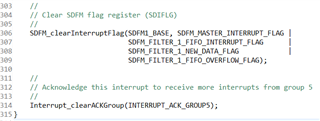
    在中断例程中、以下代码用于避免重新进入:

    关于启用 SOCA 事件代码、如下所示(Aditya 也提到了它):

    源代码如下所示供您查看:

    //###########################################################################
    //
    // FILE:   sdfm_ex5_filter_sync_fifo_cpuread.c
    //
    // TITLE:  SDFM Type 1 Filter FIFO Example.
    //
    //! \addtogroup driver_example_list
    //! <h1> SDFM Type 1 Filter FIFO </h1>
    //!
    //! This example configures SDFM1 filter to demonstrate data read through
    //! CPU in FIFO & non-FIFO mode. Data filter is configured in mode 0
    //! to select SINC3 filter with OSR of 256. Filter output is configured
    //! for 16-bit format and data shift of 10 is used.
    //!
    //! This example demonstrates the FIFO usage if enabled. FIFO length is set
    //! at 16 and data ready interrupt is configured to be triggered when FIFO is
    //! full. In this example, SDFM filter data is read by CPU in SDFM Data Ready
    //! ISR routine.
    //!
    //! \b External \b Connections \n
    //!    Connect Sigma-Delta streams to (SD-D1, SD-C1 to SD-D4,SD-C4)
    //!    on GPIO24-GPIO31
    //!
    //! \b Watch \b Variables \n
    //! -  \b filter1Result - Output of filter 1
    //!
    //
    //###########################################################################
    // $TI Release: F28004x Support Library v1.09.00.00 $
    // $Release Date: Thu Mar 19 07:26:52 IST 2020 $
    // $Copyright:
    // Copyright (C) 2020 Texas Instruments Incorporated - http://www.ti.com/
    //
    // Redistribution and use in source and binary forms, with or without 
    // modification, are permitted provided that the following conditions 
    // are met:
    // 
    //   Redistributions of source code must retain the above copyright 
    //   notice, this list of conditions and the following disclaimer.
    // 
    //   Redistributions in binary form must reproduce the above copyright
    //   notice, this list of conditions and the following disclaimer in the 
    //   documentation and/or other materials provided with the   
    //   distribution.
    // 
    //   Neither the name of Texas Instruments Incorporated nor the names of
    //   its contributors may be used to endorse or promote products derived
    //   from this software without specific prior written permission.
    // 
    // THIS SOFTWARE IS PROVIDED BY THE COPYRIGHT HOLDERS AND CONTRIBUTORS 
    // "AS IS" AND ANY EXPRESS OR IMPLIED WARRANTIES, INCLUDING, BUT NOT 
    // LIMITED TO, THE IMPLIED WARRANTIES OF MERCHANTABILITY AND FITNESS FOR
    // A PARTICULAR PURPOSE ARE DISCLAIMED. IN NO EVENT SHALL THE COPYRIGHT 
    // OWNER OR CONTRIBUTORS BE LIABLE FOR ANY DIRECT, INDIRECT, INCIDENTAL, 
    // SPECIAL, EXEMPLARY, OR CONSEQUENTIAL DAMAGES (INCLUDING, BUT NOT 
    // LIMITED TO, PROCUREMENT OF SUBSTITUTE GOODS OR SERVICES; LOSS OF USE,
    // DATA, OR PROFITS; OR BUSINESS INTERRUPTION) HOWEVER CAUSED AND ON ANY
    // THEORY OF LIABILITY, WHETHER IN CONTRACT, STRICT LIABILITY, OR TORT 
    // (INCLUDING NEGLIGENCE OR OTHERWISE) ARISING IN ANY WAY OUT OF THE USE 
    // OF THIS SOFTWARE, EVEN IF ADVISED OF THE POSSIBILITY OF SUCH DAMAGE.
    // $
    //###########################################################################
    
    //
    // Included Files
    //
    #include "driverlib.h"
    #include "device.h"
    #include <stdio.h>
    
    #define JIAKAI
    //
    // Defines
    //
    #define MAX_SAMPLES               1024
    #define FIFO_INT_NUM              2U
    #define SDFM_FILTER_ENABLE 0x2U
    
    //
    // Macro to enable FIFO mode. Make it zero to disable
    // FIFO mode.
    //
    #define ENABLE_FIFO               1
    
    //
    // Globals
    //
    int16_t  filter1Result[MAX_SAMPLES];
    #pragma DATA_SECTION(filter1Result, "Filter1_RegsFile");
    
    //
    // Function Prototypes
    //
    void configureSDFMPins(void);
    void initEPWM(uint32_t epwmInstance);
    //
    // ISRs
    //
    __interrupt void sdfmFIFO1ISR(void);
    __interrupt void sdfm1ErrorISR(void);
    
    //
    // Main
    //
    void main(void)
    {
        //
        // Initialize device clock and peripherals
        //
        Device_init();
    
        //
        // Setup GPIO by disabling pin locks and enabling pullups
        //
        Device_initGPIO();
    
        //
        // Initialize PIE and clear PIE registers. Disables CPU interrupts.
        //
        Interrupt_initModule();
    
        //
        // Initialize the PIE vector table with pointers to the shell Interrupt
        // Service Routines (ISR).
        //
        Interrupt_initVectorTable();
    
        //
        // Interrupts that are used in this example are re-mapped to
        // ISR functions found within this file.
        //
        Interrupt_clearACKGroup(INTERRUPT_ACK_GROUP5);
        Interrupt_register(INT_SDFM1DR1, sdfmFIFO1ISR);
        Interrupt_register(INT_SDFM1, sdfm1ErrorISR);
    
        //
        // Enable SDFM1 interrupts(Data Ready & Error interrupts)
        //
        Interrupt_enableMaster();
        Interrupt_enable(INT_SDFM1DR1);
        Interrupt_enable(INT_SDFM1);
    
        initEPWM(EPWM8_BASE);
    
        //
        // Configure GPIO pins as SDFM pins
        //
        configureSDFMPins();
    
        //
        // Input Control Unit
        //
        // Configure Input Control Unit: Modulator Clock rate = Modulator data rate
        //
        SDFM_setupModulatorClock(SDFM1_BASE, SDFM_FILTER_1,
                                 SDFM_MODULATOR_CLK_EQUAL_DATA_RATE);
    
        //
        // Data Filter Unit
        //
    
        // Configure Data Filter Unit - filter type, OSR value and
        // enable / disable data filter
        //
        SDFM_configDataFilter(SDFM1_BASE, (SDFM_FILTER_1 | SDFM_FILTER_SINC_3 |
               SDFM_SET_OSR(256)), (SDFM_DATA_FORMAT_16_BIT | SDFM_FILTER_ENABLE |
               SDFM_SHIFT_VALUE(0x000A)));
    
    #if (ENABLE_FIFO)
            //
            // Set data ready interrupt source as fifo interrupt
            //
            SDFM_setDataReadyInterruptSource(SDFM1_BASE, SDFM_FILTER_1,
                                             SDFM_DATA_READY_SOURCE_FIFO);
    
            //
            // Enable FIFO and set the FIFO interrupt level
            //
            SDFM_enableFIFOBuffer(SDFM1_BASE, SDFM_FILTER_1);
    
            SDFM_setFIFOInterruptLevel(SDFM1_BASE, SDFM_FILTER_1, FIFO_INT_NUM);
    
            SDFM_enableInterrupt(SDFM1_BASE, SDFM_FILTER_1,
                             (SDFM_FIFO_INTERRUPT | SDFM_FIFO_OVERFLOW_INTERRUPT));
    #else
            //
            // Set data ready interrupt source as fifo interrupt
            //
            SDFM_setDataReadyInterruptSource(SDFM1_BASE, SDFM_FILTER_1,
                                             SDFM_DATA_READY_SOURCE_DIRECT);
    
            SDFM_enableInterrupt(SDFM1_BASE, SDFM_FILTER_1,
                                 SDFM_DATA_FILTER_ACKNOWLEDGE_INTERRUPT);
    #endif
    
    
        //
        // Enable Master filter bit: Unless this bit is set none of the filter
        // modules can be enabled. All the filter modules are synchronized when
        // master filter bit is enabled after individual filter modules are enabled.
        //
        SDFM_enableMasterFilter(SDFM1_BASE);
    
        //
        // Use PWM8.CMPA signals to synchronize the filters.
        //
    #if (0)
        SDFM_disableExternalReset(SDFM1_BASE, SDFM_FILTER_1);
    #else
        SDFM_enableExternalReset(SDFM1_BASE, SDFM_FILTER_1);
        SDFM_setPWMSyncSource(SDFM1_BASE, SDFM_FILTER_1, SDFM_SYNC_PWM8_SOCA);
        SDFM_enableWaitForSync(SDFM1_BASE, SDFM_FILTER_1);
    #endif
    
        //
        // Enable modulator failure interrupt, disable threshold interrupts
        //
        SDFM_enableInterrupt(SDFM1_BASE, SDFM_FILTER_1,
                             SDFM_MODULATOR_FAILURE_INTERRUPT);
    
        SDFM_disableInterrupt(SDFM1_BASE, SDFM_FILTER_1,
                              (SDFM_HIGH_LEVEL_THRESHOLD_INTERRUPT |
                               SDFM_LOW_LEVEL_THRESHOLD_INTERRUPT));
    
        while((HWREGH(EPWM8_BASE + EPWM_O_TBCTR)) < 550);
    
        //
        // Enable master interrupt so that any of the filter interrupts can trigger
        // by SDFM interrupt to CPU
        //
        SDFM_enableMasterInterrupt(SDFM1_BASE);
    
        //
        // Enable Global Interrupt (INTM) and realtime interrupt (DBGM)
        //
        EINT;
        ERTM;
    
        //
        // Wait for an interrupt
        //
        while(1);
    }
    
    //
    // sdfm1ErrorISR - SDFM1 Error ISR
    //
    __interrupt void sdfm1ErrorISR(void)
    {
        //
        // Clear SDFM flag register (SDIFLG)
        //
        SDFM_clearInterruptFlag(SDFM1_BASE, SDFM_MASTER_INTERRUPT_FLAG |
                                0xFFFF);
    
        //
        // Acknowledge this interrupt to receive more interrupts from group 5
        //
        Interrupt_clearACKGroup(INTERRUPT_ACK_GROUP5);
    }
    
    #define PWM_TBCTR(_p)       *((uint16_t *)(0x3F04 + 0x100 * (_p)))
    int index = 0;
    uint16_t tmBuf[100];
    
    //
    // sdfmFIFO1ISR - SDFM FIFO1 ISR
    //
    __interrupt void sdfmFIFO1ISR(void)
    {
        uint16_t i;
        static uint16_t loopCounter1 = 0;
    
    #if (0)
        SDFM_setOutputDataFormat(SDFM1_BASE, SDFM_FILTER_1,
                                 SDFM_DATA_FORMAT_16_BIT);
    #endif
    
        //
        // Read SDFM flag register (SDIFLG)
        //
        if(loopCounter1 >= MAX_SAMPLES)
        {
            ESTOP0;
        }
        else if(SDFM_getFIFOISRStatus(SDFM1_BASE, SDFM_FILTER_1) == 0x1U)
        {
            tmBuf[index] = PWM_TBCTR(8); if (++index >= 100) index = 0;
            for(i = 0; i < FIFO_INT_NUM; i++)
            {
                filter1Result[loopCounter1++] =
                             (int16_t)(SDFM_getFIFOData(SDFM1_BASE,
                                                        SDFM_FILTER_1) >> 16U);
            }
    
        }
        else if(SDFM_getNewFilterDataStatus(SDFM1_BASE, SDFM_FILTER_1) == 0x1U)
        {
            filter1Result[loopCounter1++] =
                   (int16_t)(SDFM_getFilterData(SDFM1_BASE, SDFM_FILTER_1) >> 16U);
        }
    
        //
        // Clear SDFM flag register (SDIFLG)
        //
        SDFM_clearInterruptFlag(SDFM1_BASE, SDFM_MASTER_INTERRUPT_FLAG |
                                SDFM_FILTER_1_FIFO_INTERRUPT_FLAG      |
                                SDFM_FILTER_1_NEW_DATA_FLAG            |
                                SDFM_FILTER_1_FIFO_OVERFLOW_FLAG);
    
        //
        // Acknowledge this interrupt to receive more interrupts from group 5
        //
        Interrupt_clearACKGroup(INTERRUPT_ACK_GROUP5);
    }
    
    //
    // configureSDFMPins - Configure SDFM GPIOs
    //
    void configureSDFMPins(void)
    {
        uint16_t pin;
    #ifdef JIAKAI
        for(pin = 16; pin <= 17; pin++)
        {
    //        GPIO_setDirectionMode(pin, GPIO_DIR_MODE_IN);
            GPIO_setMasterCore(pin, GPIO_CORE_CPU1);
            GPIO_setPadConfig(pin, GPIO_PIN_TYPE_STD);
            GPIO_setQualificationMode(pin, GPIO_QUAL_ASYNC);
        }
        GPIO_setPinConfig(GPIO_16_SD_D1);
        GPIO_setPinConfig(GPIO_17_SD_C1);
    #else
        for(pin = 24; pin <= 31; pin++)
        {
            GPIO_setDirectionMode(pin, GPIO_DIR_MODE_IN);
            GPIO_setMasterCore(pin, GPIO_CORE_CPU1);
            GPIO_setPadConfig(pin, GPIO_PIN_TYPE_STD);
            GPIO_setQualificationMode(pin, GPIO_QUAL_ASYNC);
        }
    
        //
        // Configure GPIO16-GPIO31 as SDFM pins
        //
        GPIO_setPinConfig(GPIO_24_SD_D1);
        GPIO_setPinConfig(GPIO_25_SD_C1);
        GPIO_setPinConfig(GPIO_26_SD_D2);
        GPIO_setPinConfig(GPIO_27_SD_C2);
        GPIO_setPinConfig(GPIO_28_SD_D3);
        GPIO_setPinConfig(GPIO_29_SD_C3);
        GPIO_setPinConfig(GPIO_30_SD_D4);
        GPIO_setPinConfig(GPIO_31_SD_C4);
    #endif
    }
    
    
    //
    // initEPWM - Initialize specified EPWM settings
    //
    void initEPWM(uint32_t epwmInstance)
    {
        //
        // Disable sync(Freeze clock to PWM as well)
        //
        SysCtl_disablePeripheral(SYSCTL_PERIPH_CLK_TBCLKSYNC);
    
        //
        // Setup TBCLK: Configure timer period = 801 TBCLKs, phase = 0 &
        // clear counter
        //
        EPWM_setTimeBasePeriod(epwmInstance, 0xFFF0);
        EPWM_setPhaseShift(epwmInstance, 0U);
        EPWM_setTimeBaseCounter(epwmInstance, 0U);
    
        //
        // Set CMPA value
        //
        EPWM_setCounterCompareValue(epwmInstance, EPWM_COUNTER_COMPARE_A, 200U);
    
        //
        // Setup counter mode
        //
        EPWM_setTimeBaseCounterMode(epwmInstance, EPWM_COUNTER_MODE_UP);
        EPWM_setClockPrescaler(epwmInstance,
                               EPWM_CLOCK_DIVIDER_1,
                               EPWM_HSCLOCK_DIVIDER_1);
    
        //
        // Set actions:
        // Toggle PWMxA on event A, up-count
        // Toggle PWMxB on event A, up-count
        //
        GPIO_setPadConfig(0, GPIO_PIN_TYPE_STD);
        GPIO_setPinConfig(GPIO_0_EPWM1A);
        GPIO_setPadConfig(1, GPIO_PIN_TYPE_STD);
        GPIO_setPinConfig(GPIO_1_EPWM1B);
        EPWM_setTimeBasePeriod(EPWM1_BASE, 4);     // PWM1 period: 0.1us
        EPWM_setTimeBaseCounterMode(EPWM1_BASE, EPWM_COUNTER_MODE_UP);
        EPWM_setClockPrescaler(EPWM1_BASE,
                               EPWM_CLOCK_DIVIDER_1,
                               EPWM_HSCLOCK_DIVIDER_1);
        EPWM_setActionQualifierAction(EPWM1_BASE,
                                      EPWM_AQ_OUTPUT_A,
                                      EPWM_AQ_OUTPUT_TOGGLE,
                                      EPWM_AQ_OUTPUT_ON_TIMEBASE_PERIOD);
    //                                EPWM_AQ_OUTPUT_ON_TIMEBASE_UP_CMPA);
        EPWM_setActionQualifierAction(EPWM1_BASE,
                                      EPWM_AQ_OUTPUT_B,
                                      EPWM_AQ_OUTPUT_TOGGLE,
                                      EPWM_AQ_OUTPUT_ON_TIMEBASE_PERIOD);
    //                                EPWM_AQ_OUTPUT_ON_TIMEBASE_UP_CMPB);
    
    //#ifndef JIAKAI
        //
        // Configure SOCA signal
        //
        //
        EPWM_setADCTriggerSource(epwmInstance, EPWM_SOC_A, EPWM_SOC_TBCTR_U_CMPA);
        EPWM_setADCTriggerEventPrescale(epwmInstance, EPWM_SOC_A, 1);
    //#endif
    
        //
        // Enable sync and clock to PWM
        //
        SysCtl_enablePeripheral(SYSCTL_PERIPH_CLK_TBCLKSYNC);
    }
    
    //
    // End of file
    //
    

    谢谢、

    Jiakai

  • 请注意,本文内容源自机器翻译,可能存在语法或其它翻译错误,仅供参考。如需获取准确内容,请参阅链接中的英语原文或自行翻译。

    这是中断{__interrupt void sdfmFIFO1ISR (void)}将 ACK 上移至顶部,在进行多次调用后 ACK 位于底部。 我仍然不容易找到您在哪里或如果您启用了 SOC-A 触发器、只能看到您配置了触发源事件。

  • 请注意,本文内容源自机器翻译,可能存在语法或其它翻译错误,仅供参考。如需获取准确内容,请参阅链接中的英语原文或自行翻译。

    您好、GI、

    正确、代码未启用 SOCA、我在下面添加了它、但在 CCS 上运行代码时仍然没有区别:

    //#ifndef JIAKAI
    //
    //配置 SOCA 信号
    //
    //
    ePWM_setADCTriggerSource (epwmInstance、ePWM_SOC_A、ePWM_SOC_TBCTR_U_CMPA);
    ePWM_setADCTriggerEventPrescale (epwmInstance、ePWM_SOC_A、1);
    ePWM_enableADCtrigger (epwmInstance、ePWM_SOC_A);
    //#endif

    在中断例程 sdfmFIFO1ISR 中、 Interrupt_clearACKGroup (interrupt_ACK_group5)

    函数调用是最后一条语句。 我认为可以、调用此函数是为了允许以下 SDFM 中断。

    将其移到 ISR 顶部是可以的、但可能没有帮助(CPU 永远不会进入此 ISR)。  

    非常感谢!

    Jiakai

  • 请注意,本文内容源自机器翻译,可能存在语法或其它翻译错误,仅供参考。如需获取准确内容,请参阅链接中的英语原文或自行翻译。

    您好、Jaikai、

    我们能否验证一下、首先时钟输入是否正常? 如果您可以访问任何示波器、您是否可以将 PWM 输出连接到任何 GPIO 并验证预期的 PWM 是否出现?  

    此外、您的 SDFM 模块是否正确接收到来自 ePWM 模块的时钟信号? 您能否检查一次连接?

    Aditya

  • 请注意,本文内容源自机器翻译,可能存在语法或其它翻译错误,仅供参考。如需获取准确内容,请参阅链接中的英语原文或自行翻译。
    [引用 userid="111331" URL"~/support/microcontrollers/c2000-microcontrollers-group/c2000/f/c2000-microcontrollers-forum/1008118/tms320f280049c-the-problems-when-using-pwm-to-synchronize-sdfm/3736974 #3736974">将其移至 ISR 顶部是可以的、但可能没有帮助(CPU 从未进入此 ISR)。  [/报价]

    如果没有 LED 切换、您可能永远不知道。 单步 CCS 调试我的不会触发 ADC 中断、具体取决于调试设置等 建议始终发出中断清除第一个调用来停止回绕、重新进入甚至可能导致 CPU 停止。

    [引用 userid="111331" URL"~/support/microcontrollers/c2000-microcontrollers-group/c2000/f/c2000-microcontrollers-forum/1008118/tms320f280049c-the-problems-when-using-pwm-to-synchronize-sdfm/3736974 #3736974"](epwmInstance、ePWM_SOC_A、ePWM_SOC_TBCTR_U_CMPA);[/引用]

    是否为 CMPA 匹配计数配置/启用了动作限定符?

  • 请注意,本文内容源自机器翻译,可能存在语法或其它翻译错误,仅供参考。如需获取准确内容,请参阅链接中的英语原文或自行翻译。

    您好、Aditya、

    我已经检查了 PWM1输出、它是一个10MHz 信号、如果 Sdfm 输入时钟未连接到、也是如此

    时钟源 SDFM 将导致错误中断。

    谢谢、

    Jiakai

  • 请注意,本文内容源自机器翻译,可能存在语法或其它翻译错误,仅供参考。如需获取准确内容,请参阅链接中的英语原文或自行翻译。

    您好、GI、

    我没有使用 LED 开/关来检查程序是否进入 ISR、但我确实使用 tmBuf 来保存 PWM8.TBCTR

    当程序进入 ISR (在288行上)、但 tmBuf 保持全部为0。 我甚至把 tmBuf 移到 ISR 的开头

    但内容不变。

    谢谢、

    Jiakai

  • 请注意,本文内容源自机器翻译,可能存在语法或其它翻译错误,仅供参考。如需获取准确内容,请参阅链接中的英语原文或自行翻译。

    Jaikai、

    我在我的设置中重新创建了问题、并找到了 GI 突出显示的问题。 问题在于 EPWM8 SOCA 事件未生成、最终将停止 SDSYNC 事件生成。 因此、我们不会看到 CPU 进入 ISR。

    在 EPWM 初始化内部、当进入时、您需要禁用 EPWM ADC 触发器、并在离开 EPWM 初始化块时将其重新启用。 只要我们需要使用来自 ePWM 模块的 ADC SOC 信号、就必须保持此流程。

    连接初始化代码、这有助于我使代码正常工作。

    //
    // initEPWM - Initialize specified EPWM settings
    //
    void initEPWM(uint32_t epwmInstance)
    {
        //
        // Disable sync(Freeze clock to PWM as well)
        //
        SysCtl_disablePeripheral(SYSCTL_PERIPH_CLK_TBCLKSYNC);
        EPWM_disableADCTrigger(EPWM8_BASE, EPWM_SOC_A);
    
        //
        // Setup TBCLK: Configure timer period = 801 TBCLKs, phase = 0 &
        // clear counter
        //
        EPWM_setTimeBasePeriod(epwmInstance, 0xFFF0);
        EPWM_setPhaseShift(epwmInstance, 0U);
        EPWM_setTimeBaseCounter(epwmInstance, 0U);
    
        //
        // Set CMPA value
        //
        EPWM_setCounterCompareValue(epwmInstance, EPWM_COUNTER_COMPARE_A, 200U);
    
        //
        // Setup counter mode
        //
        EPWM_setTimeBaseCounterMode(epwmInstance, EPWM_COUNTER_MODE_UP);
        EPWM_setClockPrescaler(epwmInstance,
                               EPWM_CLOCK_DIVIDER_1,
                               EPWM_HSCLOCK_DIVIDER_1);
    
        //
        // Set actions:
        // Toggle PWMxA on event A, up-count
        // Toggle PWMxB on event A, up-count
        //
        GPIO_setPadConfig(0, GPIO_PIN_TYPE_STD);
        GPIO_setPinConfig(GPIO_0_EPWM1A);
        GPIO_setPadConfig(1, GPIO_PIN_TYPE_STD);
        GPIO_setPinConfig(GPIO_1_EPWM1B);
        EPWM_setTimeBasePeriod(EPWM1_BASE, 4);     // PWM1 period: 0.1us
        EPWM_setTimeBaseCounterMode(EPWM1_BASE, EPWM_COUNTER_MODE_UP);
        EPWM_setClockPrescaler(EPWM1_BASE,
                               EPWM_CLOCK_DIVIDER_1,
                               EPWM_HSCLOCK_DIVIDER_1);
        EPWM_setActionQualifierAction(EPWM1_BASE,
                                      EPWM_AQ_OUTPUT_A,
                                      EPWM_AQ_OUTPUT_TOGGLE,
                                      EPWM_AQ_OUTPUT_ON_TIMEBASE_PERIOD);
    //                                EPWM_AQ_OUTPUT_ON_TIMEBASE_UP_CMPA);
        EPWM_setActionQualifierAction(EPWM1_BASE,
                                      EPWM_AQ_OUTPUT_B,
                                      EPWM_AQ_OUTPUT_TOGGLE,
                                      EPWM_AQ_OUTPUT_ON_TIMEBASE_PERIOD);
    //                                EPWM_AQ_OUTPUT_ON_TIMEBASE_UP_CMPB);
    
    //#ifndef JIAKAI
        //
        // Configure SOCA signal
        //
        //
    //    EPWM_setADCTriggerSource(EPWM1_BASE, EPWM_SOC_A, EPWM_SOC_TBCTR_U_CMPA);
    //    EPWM_setADCTriggerEventPrescale(EPWM1_BASE, EPWM_SOC_A, 1);
    //#endif
    
        EPWM_setADCTriggerSource(EPWM8_BASE, EPWM_SOC_A, EPWM_SOC_TBCTR_U_CMPA);
        EPWM_setADCTriggerEventPrescale(EPWM8_BASE, EPWM_SOC_A, 1);
    
        //
        // Enable sync and clock to PWM
        //
        EPWM_enableADCTrigger(EPWM8_BASE, EPWM_SOC_A);
        SysCtl_enablePeripheral(SYSCTL_PERIPH_CLK_TBCLKSYNC);
    }

    希望这对您有所帮助。

    Aditya

  • 请注意,本文内容源自机器翻译,可能存在语法或其它翻译错误,仅供参考。如需获取准确内容,请参阅链接中的英语原文或自行翻译。

    您好、Aditya、

    我在 函数 initEPWM 的开头(放置代码的位置)添加了 ePWM_disableADCTrigger、但仍然没有更改。

    我已经检查了 PWM8.ETSEL.SOCAEN、在调用  ePWM_DisableADCTrigger 之前它是0。

    我还认为在初始化 SDFM 之前、以下3个函数调用(启用 SDFM 中断)不是很好、

    我将它们移动到所有器件都已初始化的位置、但结果仍然相同。

    更改代码如下所示:

    //###########################################################################
    //
    // FILE:   sdfm_ex5_filter_sync_fifo_cpuread.c
    //
    // TITLE:  SDFM Type 1 Filter FIFO Example.
    //
    //! \addtogroup driver_example_list
    //! <h1> SDFM Type 1 Filter FIFO </h1>
    //!
    //! This example configures SDFM1 filter to demonstrate data read through
    //! CPU in FIFO & non-FIFO mode. Data filter is configured in mode 0
    //! to select SINC3 filter with OSR of 256. Filter output is configured
    //! for 16-bit format and data shift of 10 is used.
    //!
    //! This example demonstrates the FIFO usage if enabled. FIFO length is set
    //! at 16 and data ready interrupt is configured to be triggered when FIFO is
    //! full. In this example, SDFM filter data is read by CPU in SDFM Data Ready
    //! ISR routine.
    //!
    //! \b External \b Connections \n
    //!    Connect Sigma-Delta streams to (SD-D1, SD-C1 to SD-D4,SD-C4)
    //!    on GPIO24-GPIO31
    //!
    //! \b Watch \b Variables \n
    //! -  \b filter1Result - Output of filter 1
    //!
    //
    //###########################################################################
    // $TI Release: F28004x Support Library v1.09.00.00 $
    // $Release Date: Thu Mar 19 07:26:52 IST 2020 $
    // $Copyright:
    // Copyright (C) 2020 Texas Instruments Incorporated - http://www.ti.com/
    //
    // Redistribution and use in source and binary forms, with or without 
    // modification, are permitted provided that the following conditions 
    // are met:
    // 
    //   Redistributions of source code must retain the above copyright 
    //   notice, this list of conditions and the following disclaimer.
    // 
    //   Redistributions in binary form must reproduce the above copyright
    //   notice, this list of conditions and the following disclaimer in the 
    //   documentation and/or other materials provided with the   
    //   distribution.
    // 
    //   Neither the name of Texas Instruments Incorporated nor the names of
    //   its contributors may be used to endorse or promote products derived
    //   from this software without specific prior written permission.
    // 
    // THIS SOFTWARE IS PROVIDED BY THE COPYRIGHT HOLDERS AND CONTRIBUTORS 
    // "AS IS" AND ANY EXPRESS OR IMPLIED WARRANTIES, INCLUDING, BUT NOT 
    // LIMITED TO, THE IMPLIED WARRANTIES OF MERCHANTABILITY AND FITNESS FOR
    // A PARTICULAR PURPOSE ARE DISCLAIMED. IN NO EVENT SHALL THE COPYRIGHT 
    // OWNER OR CONTRIBUTORS BE LIABLE FOR ANY DIRECT, INDIRECT, INCIDENTAL, 
    // SPECIAL, EXEMPLARY, OR CONSEQUENTIAL DAMAGES (INCLUDING, BUT NOT 
    // LIMITED TO, PROCUREMENT OF SUBSTITUTE GOODS OR SERVICES; LOSS OF USE,
    // DATA, OR PROFITS; OR BUSINESS INTERRUPTION) HOWEVER CAUSED AND ON ANY
    // THEORY OF LIABILITY, WHETHER IN CONTRACT, STRICT LIABILITY, OR TORT 
    // (INCLUDING NEGLIGENCE OR OTHERWISE) ARISING IN ANY WAY OUT OF THE USE 
    // OF THIS SOFTWARE, EVEN IF ADVISED OF THE POSSIBILITY OF SUCH DAMAGE.
    // $
    //###########################################################################
    
    //
    // Included Files
    //
    #include "driverlib.h"
    #include "device.h"
    #include <stdio.h>
    
    #define JIAKAI
    //
    // Defines
    //
    #define MAX_SAMPLES               1024
    #define FIFO_INT_NUM              2U
    #define SDFM_FILTER_ENABLE 0x2U
    
    //
    // Macro to enable FIFO mode. Make it zero to disable
    // FIFO mode.
    //
    #define ENABLE_FIFO               1
    
    //
    // Globals
    //
    int16_t  filter1Result[MAX_SAMPLES];
    #pragma DATA_SECTION(filter1Result, "Filter1_RegsFile");
    
    //
    // Function Prototypes
    //
    void configureSDFMPins(void);
    void initEPWM(uint32_t epwmInstance);
    //
    // ISRs
    //
    __interrupt void sdfmFIFO1ISR(void);
    __interrupt void sdfm1ErrorISR(void);
    
    //
    // Main
    //
    void main(void)
    {
        //
        // Initialize device clock and peripherals
        //
        Device_init();
    
        //
        // Setup GPIO by disabling pin locks and enabling pullups
        //
        Device_initGPIO();
    
        //
        // Initialize PIE and clear PIE registers. Disables CPU interrupts.
        //
        Interrupt_initModule();
    
        //
        // Initialize the PIE vector table with pointers to the shell Interrupt
        // Service Routines (ISR).
        //
        Interrupt_initVectorTable();
    
        //
        // Interrupts that are used in this example are re-mapped to
        // ISR functions found within this file.
        //
        Interrupt_clearACKGroup(INTERRUPT_ACK_GROUP5);
        Interrupt_register(INT_SDFM1DR1, sdfmFIFO1ISR);
        Interrupt_register(INT_SDFM1, sdfm1ErrorISR);
    
        //
        // Enable SDFM1 interrupts(Data Ready & Error interrupts)
        //
    #if (0) // need to move to the palce that all devices are initialized
        Interrupt_enableMaster();
        Interrupt_enable(INT_SDFM1DR1);
        Interrupt_enable(INT_SDFM1);
    #endif
        initEPWM(EPWM8_BASE);
    
        //
        // Configure GPIO pins as SDFM pins
        //
        configureSDFMPins();
    
        //
        // Input Control Unit
        //
        // Configure Input Control Unit: Modulator Clock rate = Modulator data rate
        //
        SDFM_setupModulatorClock(SDFM1_BASE, SDFM_FILTER_1,
                                 SDFM_MODULATOR_CLK_EQUAL_DATA_RATE);
    
        //
        // Data Filter Unit
        //
    
        // Configure Data Filter Unit - filter type, OSR value and
        // enable / disable data filter
        //
        SDFM_configDataFilter(SDFM1_BASE, (SDFM_FILTER_1 | SDFM_FILTER_SINC_3 |
               SDFM_SET_OSR(256)), (SDFM_DATA_FORMAT_16_BIT | SDFM_FILTER_ENABLE |
               SDFM_SHIFT_VALUE(0x000A)));
    
    #if (ENABLE_FIFO)
            //
            // Set data ready interrupt source as fifo interrupt
            //
            SDFM_setDataReadyInterruptSource(SDFM1_BASE, SDFM_FILTER_1,
                                             SDFM_DATA_READY_SOURCE_FIFO);
    
            //
            // Enable FIFO and set the FIFO interrupt level
            //
            SDFM_enableFIFOBuffer(SDFM1_BASE, SDFM_FILTER_1);
    
            SDFM_setFIFOInterruptLevel(SDFM1_BASE, SDFM_FILTER_1, FIFO_INT_NUM);
    
            SDFM_enableInterrupt(SDFM1_BASE, SDFM_FILTER_1,
                             (SDFM_FIFO_INTERRUPT | SDFM_FIFO_OVERFLOW_INTERRUPT));
    #else
            //
            // Set data ready interrupt source as fifo interrupt
            //
            SDFM_setDataReadyInterruptSource(SDFM1_BASE, SDFM_FILTER_1,
                                             SDFM_DATA_READY_SOURCE_DIRECT);
    
            SDFM_enableInterrupt(SDFM1_BASE, SDFM_FILTER_1,
                                 SDFM_DATA_FILTER_ACKNOWLEDGE_INTERRUPT);
    #endif
    
    
        //
        // Enable Master filter bit: Unless this bit is set none of the filter
        // modules can be enabled. All the filter modules are synchronized when
        // master filter bit is enabled after individual filter modules are enabled.
        //
        SDFM_enableMasterFilter(SDFM1_BASE);
    
        //
        // Use PWM8.CMPA signals to synchronize the filters.
        //
    #if (0)
        SDFM_disableExternalReset(SDFM1_BASE, SDFM_FILTER_1);
    #else
        SDFM_enableExternalReset(SDFM1_BASE, SDFM_FILTER_1);
        SDFM_setPWMSyncSource(SDFM1_BASE, SDFM_FILTER_1, SDFM_SYNC_PWM8_SOCA);
        SDFM_enableWaitForSync(SDFM1_BASE, SDFM_FILTER_1);
    #endif
    
        //
        // Enable modulator failure interrupt, disable threshold interrupts
        //
        SDFM_enableInterrupt(SDFM1_BASE, SDFM_FILTER_1,
                             SDFM_MODULATOR_FAILURE_INTERRUPT);
    
        SDFM_disableInterrupt(SDFM1_BASE, SDFM_FILTER_1,
                              (SDFM_HIGH_LEVEL_THRESHOLD_INTERRUPT |
                               SDFM_LOW_LEVEL_THRESHOLD_INTERRUPT));
    
        while((HWREGH(EPWM8_BASE + EPWM_O_TBCTR)) < 550);
    
        //
        // Enable master interrupt so that any of the filter interrupts can trigger
        // by SDFM interrupt to CPU
        //
        SDFM_enableMasterInterrupt(SDFM1_BASE);
    
    #if (1) // need to move to the palce that all devices are initialized
        Interrupt_enableMaster();
        Interrupt_enable(INT_SDFM1DR1);
        Interrupt_enable(INT_SDFM1);
    #endif
    
        //
        // Enable Global Interrupt (INTM) and realtime interrupt (DBGM)
        //
        EINT;
        ERTM;
    
        //
        // Wait for an interrupt
        //
        while(1);
    }
    
    //
    // sdfm1ErrorISR - SDFM1 Error ISR
    //
    __interrupt void sdfm1ErrorISR(void)
    {
        //
        // Clear SDFM flag register (SDIFLG)
        //
        SDFM_clearInterruptFlag(SDFM1_BASE, SDFM_MASTER_INTERRUPT_FLAG |
                                0xFFFF);
    
        //
        // Acknowledge this interrupt to receive more interrupts from group 5
        //
        Interrupt_clearACKGroup(INTERRUPT_ACK_GROUP5);
    }
    
    #define PWM_TBCTR(_p)       *((uint16_t *)(0x3F04 + 0x100 * (_p)))
    int index = 0;
    uint16_t tmBuf[100];
    
    //
    // sdfmFIFO1ISR - SDFM FIFO1 ISR
    //
    __interrupt void sdfmFIFO1ISR(void)
    {
        uint16_t i;
        static uint16_t loopCounter1 = 0;
    
    #if (0)
        SDFM_setOutputDataFormat(SDFM1_BASE, SDFM_FILTER_1,
                                 SDFM_DATA_FORMAT_16_BIT);
    #endif
    
        //
        // Read SDFM flag register (SDIFLG)
        //
        if(loopCounter1 >= MAX_SAMPLES)
        {
            ESTOP0;
        }
        else if(SDFM_getFIFOISRStatus(SDFM1_BASE, SDFM_FILTER_1) == 0x1U)
        {
            tmBuf[index] = PWM_TBCTR(8); if (++index >= 100) index = 0;
            for(i = 0; i < FIFO_INT_NUM; i++)
            {
                filter1Result[loopCounter1++] =
                             (int16_t)(SDFM_getFIFOData(SDFM1_BASE,
                                                        SDFM_FILTER_1) >> 16U);
            }
    
        }
        else if(SDFM_getNewFilterDataStatus(SDFM1_BASE, SDFM_FILTER_1) == 0x1U)
        {
            filter1Result[loopCounter1++] =
                   (int16_t)(SDFM_getFilterData(SDFM1_BASE, SDFM_FILTER_1) >> 16U);
        }
    
        //
        // Clear SDFM flag register (SDIFLG)
        //
        SDFM_clearInterruptFlag(SDFM1_BASE, SDFM_MASTER_INTERRUPT_FLAG |
                                SDFM_FILTER_1_FIFO_INTERRUPT_FLAG      |
                                SDFM_FILTER_1_NEW_DATA_FLAG            |
                                SDFM_FILTER_1_FIFO_OVERFLOW_FLAG);
    
        //
        // Acknowledge this interrupt to receive more interrupts from group 5
        //
        Interrupt_clearACKGroup(INTERRUPT_ACK_GROUP5);
    }
    
    //
    // configureSDFMPins - Configure SDFM GPIOs
    //
    void configureSDFMPins(void)
    {
        uint16_t pin;
    #ifdef JIAKAI
        for(pin = 16; pin <= 17; pin++)
        {
    //        GPIO_setDirectionMode(pin, GPIO_DIR_MODE_IN);
            GPIO_setMasterCore(pin, GPIO_CORE_CPU1);
            GPIO_setPadConfig(pin, GPIO_PIN_TYPE_STD);
            GPIO_setQualificationMode(pin, GPIO_QUAL_ASYNC);
        }
        GPIO_setPinConfig(GPIO_16_SD_D1);
        GPIO_setPinConfig(GPIO_17_SD_C1);
    #else
        for(pin = 24; pin <= 31; pin++)
        {
            GPIO_setDirectionMode(pin, GPIO_DIR_MODE_IN);
            GPIO_setMasterCore(pin, GPIO_CORE_CPU1);
            GPIO_setPadConfig(pin, GPIO_PIN_TYPE_STD);
            GPIO_setQualificationMode(pin, GPIO_QUAL_ASYNC);
        }
    
        //
        // Configure GPIO16-GPIO31 as SDFM pins
        //
        GPIO_setPinConfig(GPIO_24_SD_D1);
        GPIO_setPinConfig(GPIO_25_SD_C1);
        GPIO_setPinConfig(GPIO_26_SD_D2);
        GPIO_setPinConfig(GPIO_27_SD_C2);
        GPIO_setPinConfig(GPIO_28_SD_D3);
        GPIO_setPinConfig(GPIO_29_SD_C3);
        GPIO_setPinConfig(GPIO_30_SD_D4);
        GPIO_setPinConfig(GPIO_31_SD_C4);
    #endif
    }
    
    
    //
    // initEPWM - Initialize specified EPWM settings
    //
    void initEPWM(uint32_t epwmInstance)
    {
        //
        // Disable sync(Freeze clock to PWM as well)
        //
        SysCtl_disablePeripheral(SYSCTL_PERIPH_CLK_TBCLKSYNC);
        EPWM_disableADCTrigger(epwmInstance, EPWM_SOC_A);
    
        //
        // Setup TBCLK: Configure timer period = 801 TBCLKs, phase = 0 &
        // clear counter
        //
        EPWM_setTimeBasePeriod(epwmInstance, 0xFFF0);
        EPWM_setPhaseShift(epwmInstance, 0U);
        EPWM_setTimeBaseCounter(epwmInstance, 0U);
    
        //
        // Set CMPA value
        //
        EPWM_setCounterCompareValue(epwmInstance, EPWM_COUNTER_COMPARE_A, 200U);
    
        //
        // Setup counter mode
        //
        EPWM_setTimeBaseCounterMode(epwmInstance, EPWM_COUNTER_MODE_UP);
        EPWM_setClockPrescaler(epwmInstance,
                               EPWM_CLOCK_DIVIDER_1,
                               EPWM_HSCLOCK_DIVIDER_1);
    
        //
        // Set actions:
        // Toggle PWMxA on event A, up-count
        // Toggle PWMxB on event A, up-count
        //
        GPIO_setPadConfig(0, GPIO_PIN_TYPE_STD);
        GPIO_setPinConfig(GPIO_0_EPWM1A);
        GPIO_setPadConfig(1, GPIO_PIN_TYPE_STD);
        GPIO_setPinConfig(GPIO_1_EPWM1B);
        EPWM_setTimeBasePeriod(EPWM1_BASE, 4);     // PWM1 period: 0.1us
        EPWM_setTimeBaseCounterMode(EPWM1_BASE, EPWM_COUNTER_MODE_UP);
        EPWM_setClockPrescaler(EPWM1_BASE,
                               EPWM_CLOCK_DIVIDER_1,
                               EPWM_HSCLOCK_DIVIDER_1);
        EPWM_setActionQualifierAction(EPWM1_BASE,
                                      EPWM_AQ_OUTPUT_A,
                                      EPWM_AQ_OUTPUT_TOGGLE,
                                      EPWM_AQ_OUTPUT_ON_TIMEBASE_PERIOD);
    //                                EPWM_AQ_OUTPUT_ON_TIMEBASE_UP_CMPA);
        EPWM_setActionQualifierAction(EPWM1_BASE,
                                      EPWM_AQ_OUTPUT_B,
                                      EPWM_AQ_OUTPUT_TOGGLE,
                                      EPWM_AQ_OUTPUT_ON_TIMEBASE_PERIOD);
    //                                EPWM_AQ_OUTPUT_ON_TIMEBASE_UP_CMPB);
    
    //#ifndef JIAKAI
        //
        // Configure SOCA signal
        //
        //
        EPWM_setADCTriggerSource(epwmInstance, EPWM_SOC_A, EPWM_SOC_TBCTR_U_CMPA);
        EPWM_setADCTriggerEventPrescale(epwmInstance, EPWM_SOC_A, 1);
        EPWM_enableADCTrigger(epwmInstance, EPWM_SOC_A);
    //#endif
    
        //
        // Enable sync and clock to PWM
        //
        SysCtl_enablePeripheral(SYSCTL_PERIPH_CLK_TBCLKSYNC);
    }
    
    //
    // End of file
    //
    

    谢谢、

    Jiakai

  • 请注意,本文内容源自机器翻译,可能存在语法或其它翻译错误,仅供参考。如需获取准确内容,请参阅链接中的英语原文或自行翻译。

    Jaikai、

    使用您发送的代码、我能够看到 CPU 进入 sdfmFIFO1ISR、 并且 EPwm8Regs.ETFlG.SOCA 变为高电平。 您能否在结束时再次检查一次?

    如果无法解决、您能否共享压缩的项目? 我可以检查任何链接文件中的差异。

    Aditya

  • 请注意,本文内容源自机器翻译,可能存在语法或其它翻译错误,仅供参考。如需获取准确内容,请参阅链接中的英语原文或自行翻译。

    您好、Aditya、

    我没有创建项目、只需更改 C2000ware 项目中的 sdfm_ex5_filter_sync_fifo_cpuread.c 文件、路径如下:

    C:\ti\c2000Ware_3_02_00_00\driverlib\f28004x\examples\sdfm\sdfm_ex5_filter_sync_fifo_cpuread.c

    谢谢、

    Jiakai

  • 请注意,本文内容源自机器翻译,可能存在语法或其它翻译错误,仅供参考。如需获取准确内容,请参阅链接中的英语原文或自行翻译。

    您好、Jaikai、

    您能否安装最新的 C2000Ware 并尝试运行您的项目? 某些错误修复可能会帮助您的最终代码正常工作。 我在 C2000Ware_3_04版本上运行了示例代码。

    下载 C2000Ware 的链接: C2000WARE 软件开发套件(SDK)|德州仪器 TI.com

    谢谢、

    Aditya

  • 请注意,本文内容源自机器翻译,可能存在语法或其它翻译错误,仅供参考。如需获取准确内容,请参阅链接中的英语原文或自行翻译。

    您好、Aditya、

    我有 C2000Ware_3_04、因为我的 CCS 是 v9、它无法打开 C2000Ware_3_04项目、

    因此我使用 C2000Ware_3_02项目。

    我已经在 两个版本中比较了 sdfm_ex5_filter_sync_fifo_cpuread.c、没有区别

    在 CPU 器件初始化代码中、唯一的区别是 2000Ware_3_04 更改了 SDFM 引脚配置

    名称。

    我将安装最新的 CCS 以进行确认。

    谢谢、

    Jiakai  

  • 请注意,本文内容源自机器翻译,可能存在语法或其它翻译错误,仅供参考。如需获取准确内容,请参阅链接中的英语原文或自行翻译。

    您好、Jaikai、  

    很抱歉您遇到问题。 更改不仅仅是针对源代码。 我认为、辅助驾驶员可能会导致一些问题。 您共享的源代码在我的末尾运行得非常好

    Aditya

  • 请注意,本文内容源自机器翻译,可能存在语法或其它翻译错误,仅供参考。如需获取准确内容,请参阅链接中的英语原文或自行翻译。

    如果将更新的 driverlib 导入到现有工程中是根本原因、则看起来会更容易。 导入高级选项"仅创建源链接"而不是导入整个库文件似乎是一个很好的解决方法。  

  • 请注意,本文内容源自机器翻译,可能存在语法或其它翻译错误,仅供参考。如需获取准确内容,请参阅链接中的英语原文或自行翻译。

    Jaikai、

    我尝试在 C2000Ware_3_02版本上运行该代码、它也可以在那里运行。 我可以看到代码在 sdfmFIFO1ISR 内部停止。

    您是否能够在最终取得任何成功?

    Aditya

  • 请注意,本文内容源自机器翻译,可能存在语法或其它翻译错误,仅供参考。如需获取准确内容,请参阅链接中的英语原文或自行翻译。

    您好、Aditya 和 GI、

    由于 GI 的建议对我来说很容易、因此我将项目更改为将 C2000Ware 转换为 v3.4。

    当我运行项目时、程序仅输入 sdfm1ErrorISR、从未输入 sdfmFIFO1ISR。

    我很匆忙地解决了问题、因此我安装了 CCS v10.3.1和最新的 C200Ware。

    我在 CCS v10.3.1上运行该程序、但仍然存在与在另一台计算机上相同的问题。

    我设置2个计数器:cntErr 和 cntDat、cntErr 用于计算进入  sdfm1ErrorISR 的次数、

    cntDat 用于对进入 sdfmFIFO1ISR 的时间进行计数。 运行几秒钟后、2个计数器值如下所示:

    源代码如下:

    //###########################################################################
    //
    // FILE:   sdfm.h
    //
    // TITLE:   C28x SDFM Driver
    //
    //###########################################################################
    // $TI Release: F28004x Support Library v1.12.00.00 $
    // $Release Date: Fri Feb 12 18:57:27 IST 2021 $
    // $Copyright:
    // Copyright (C) 2021 Texas Instruments Incorporated - http://www.ti.com/
    //
    // Redistribution and use in source and binary forms, with or without 
    // modification, are permitted provided that the following conditions 
    // are met:
    // 
    //   Redistributions of source code must retain the above copyright 
    //   notice, this list of conditions and the following disclaimer.
    // 
    //   Redistributions in binary form must reproduce the above copyright
    //   notice, this list of conditions and the following disclaimer in the 
    //   documentation and/or other materials provided with the   
    //   distribution.
    // 
    //   Neither the name of Texas Instruments Incorporated nor the names of
    //   its contributors may be used to endorse or promote products derived
    //   from this software without specific prior written permission.
    // 
    // THIS SOFTWARE IS PROVIDED BY THE COPYRIGHT HOLDERS AND CONTRIBUTORS 
    // "AS IS" AND ANY EXPRESS OR IMPLIED WARRANTIES, INCLUDING, BUT NOT 
    // LIMITED TO, THE IMPLIED WARRANTIES OF MERCHANTABILITY AND FITNESS FOR
    // A PARTICULAR PURPOSE ARE DISCLAIMED. IN NO EVENT SHALL THE COPYRIGHT 
    // OWNER OR CONTRIBUTORS BE LIABLE FOR ANY DIRECT, INDIRECT, INCIDENTAL, 
    // SPECIAL, EXEMPLARY, OR CONSEQUENTIAL DAMAGES (INCLUDING, BUT NOT 
    // LIMITED TO, PROCUREMENT OF SUBSTITUTE GOODS OR SERVICES; LOSS OF USE,
    // DATA, OR PROFITS; OR BUSINESS INTERRUPTION) HOWEVER CAUSED AND ON ANY
    // THEORY OF LIABILITY, WHETHER IN CONTRACT, STRICT LIABILITY, OR TORT 
    // (INCLUDING NEGLIGENCE OR OTHERWISE) ARISING IN ANY WAY OUT OF THE USE 
    // OF THIS SOFTWARE, EVEN IF ADVISED OF THE POSSIBILITY OF SUCH DAMAGE.
    // $
    //###########################################################################
    #ifndef SDFM_H
    #define SDFM_H
    
    //*****************************************************************************
    //
    // If building with a C++ compiler, make all of the definitions in this header
    // have a C binding.
    //
    //*****************************************************************************
    
    #ifdef __cplusplus
    extern "C"
    {
    #endif
    
    //*****************************************************************************
    //
    //! \addtogroup sdfm_api SDFM
    //! @{
    //
    //*****************************************************************************
    
    #include <stdbool.h>
    #include <stdint.h>
    #include "inc/hw_types.h"
    #include "inc/hw_sdfm.h"
    #include "inc/hw_memmap.h"
    #include "cpu.h"
    #include "debug.h"
    
    //*****************************************************************************
    //
    // Defines for the API.
    //
    //*****************************************************************************
    //! Macro to get the low threshold
    //!
    #define SDFM_GET_LOW_THRESHOLD(C)    ((uint16_t)(C))
    
    //! Macro to get the high threshold
    //!
    #define SDFM_GET_HIGH_THRESHOLD(C)   ((uint16_t)((uint32_t)(C) >> 16U))
    
    
    //! Macro to convert comparator over sampling ratio to acceptable bit location
    //!
    #define SDFM_SET_OSR(X)         (((X) - 1) << 8U)
    //! Macro to convert the data shift bit values to acceptable bit location
    //!
    #define SDFM_SHIFT_VALUE(X)     ((X) << 2U)
    
    //! Macro to combine high threshold and low threshold values
    //!
    #define SDFM_THRESHOLD(H, L)     ((((uint32_t)(H)) << 16U) | (L))
    
    //! Macro to set the FIFO level to acceptable bit location
    //!
    #define SDFM_SET_FIFO_LEVEL(X)  ((X) << 7U)
    
    //! Macro to set and enable the zero cross threshold value.
    //!
    #define SDFM_SET_ZERO_CROSS_THRESH_VALUE(X) (0x8000 | (X))
    
    //! Macros to enable or disable filter.
    //!
    #define SDFM_FILTER_DISABLE     0x0U
    #define SDFM_FILTER_ENABLE      0x2U
    
    //*****************************************************************************
    //
    //! Values that can be returned from SDFM_getThresholdStatus()
    //
    //*****************************************************************************
    typedef enum
    {
        SDFM_OUTPUT_WITHIN_THRESHOLD = 0,   //!< SDFM output is within threshold
        SDFM_OUTPUT_ABOVE_THRESHOLD  = 1,   //!< SDFM output is above threshold
        SDFM_OUTPUT_BELOW_THRESHOLD  = 2    //!< SDFM output is below threshold
    } SDFM_OutputThresholdStatus;
    
    //*****************************************************************************
    //
    //! Values that can be passed to all functions as the \e filterNumber
    //! parameter.
    //
    //*****************************************************************************
    typedef enum
    {
        SDFM_FILTER_1 = 0, //!< Digital filter 1
        SDFM_FILTER_2 = 1, //!< Digital filter 2
        SDFM_FILTER_3 = 2, //!< Digital filter 3
        SDFM_FILTER_4 = 3  //!< Digital filter 4
    } SDFM_FilterNumber;
    
    //*****************************************************************************
    //
    //! Values that can be passed to SDFM_setFilterType(),
    //! SDFM_setComparatorFilterType() as the \e filterType parameter.
    //
    //*****************************************************************************
    typedef enum
    {
        //! Digital filter with SincFast structure.
        SDFM_FILTER_SINC_FAST = 0x00,
        //! Digital filter with Sinc1 structure
        SDFM_FILTER_SINC_1    = 0x10,
        //! Digital filter with Sinc3 structure.
        SDFM_FILTER_SINC_2    = 0x20,
        //! Digital filter with Sinc4 structure.
        SDFM_FILTER_SINC_3    = 0x30
    } SDFM_FilterType;
    
    //*****************************************************************************
    //
    //! Values that can be passed to SDFM_setupModulatorClock(),as the
    //! \e clockMode parameter.
    //
    //*****************************************************************************
    typedef enum
    {
       //! Modulator clock is identical to the data rate
       SDFM_MODULATOR_CLK_EQUAL_DATA_RATE  = 0,
       //! Modulator clock is half the data rate
       SDFM_MODULATOR_CLK_HALF_DATA_RATE   = 1,
       //! Modulator clock is off. Data is Manchester coded.
       SDFM_MODULATOR_CLK_OFF              = 2,
       //! Modulator clock is double the data rate.
       SDFM_MODULATOR_CLK_DOUBLE_DATA_RATE = 3
    } SDFM_ModulatorClockMode;
    
    //*****************************************************************************
    //
    //! Values that can be passed to SDFM_setOutputDataFormat(),as the
    //! \e dataFormat parameter.
    //
    //*****************************************************************************
    typedef enum
    {
       //! Filter output is in 16 bits 2's complement format.
       SDFM_DATA_FORMAT_16_BIT = 0,
       //! Filter output is in 32 bits 2's complement format.
       SDFM_DATA_FORMAT_32_BIT = 1
    } SDFM_OutputDataFormat;
    
    //*****************************************************************************
    //
    //! Values that can be passed to SDFM_setDataReadyInterruptSource(),as the
    //! \e dataReadySource parameter.
    //
    //*****************************************************************************
    typedef enum
    {
       //! Data ready interrupt source is direct (non -FIFO).
       SDFM_DATA_READY_SOURCE_DIRECT = 0,
       //! Data ready interrupt source is FIFO.
       SDFM_DATA_READY_SOURCE_FIFO = 1
    } SDFM_DataReadyInterruptSource;
    
    //*****************************************************************************
    //
    //! Values that can be passed to SDFM_setPWMSyncSource(),as the
    //! \e syncSource parameter.
    //
    //*****************************************************************************
    typedef enum
    {
       SDFM_SYNC_PWM1_SOCA = 0,    //!< SDFM sync source is PWM1 SOCA
       SDFM_SYNC_PWM1_SOCB = 1,    //!< SDFM sync source is PWM1 SOCB
       SDFM_SYNC_PWM2_SOCA = 4,    //!< SDFM sync source is PWM2 SOCA
       SDFM_SYNC_PWM2_SOCB = 5,    //!< SDFM sync source is PWM2 SOCB
       SDFM_SYNC_PWM3_SOCA = 8,    //!< SDFM sync source is PWM3 SOCA
       SDFM_SYNC_PWM3_SOCB = 9,    //!< SDFM sync source is PWM3 SOCB
       SDFM_SYNC_PWM4_SOCA = 12,   //!< SDFM sync source is PWM4 SOCA
       SDFM_SYNC_PWM4_SOCB = 13,   //!< SDFM sync source is PWM4 SOCB
       SDFM_SYNC_PWM5_SOCA = 16,   //!< SDFM sync source is PWM5 SOCA
       SDFM_SYNC_PWM5_SOCB = 17,   //!< SDFM sync source is PWM5 SOCB
       SDFM_SYNC_PWM6_SOCA = 20,   //!< SDFM sync source is PWM6 SOCA
       SDFM_SYNC_PWM6_SOCB = 21,   //!< SDFM sync source is PWM6 SOCB
       SDFM_SYNC_PWM7_SOCA = 24,   //!< SDFM sync source is PWM7 SOCA
       SDFM_SYNC_PWM7_SOCB = 25,   //!< SDFM sync source is PWM7 SOCB
       SDFM_SYNC_PWM8_SOCA = 28,   //!< SDFM sync source is PWM8 SOCA
       SDFM_SYNC_PWM8_SOCB = 29    //!< SDFM sync source is PWM8 SOCB
    } SDFM_PWMSyncSource;
    
    //*****************************************************************************
    //
    //! Values that can be passed to SDFM_setFIFOClearOnSyncMode(),as the
    //! \e fifoClearSyncMode parameter.
    //
    //*****************************************************************************
    typedef enum
    {
       //! SDFM FIFO buffer is not cleared on Sync signal
       SDFM_FIFO_NOT_CLEARED_ON_SYNC = 0,
       //! SDFM FIFO buffer is cleared on Sync signal
       SDFM_FIFO_CLEARED_ON_SYNC     = 1
    } SDFM_FIFOClearSyncMode;
    
    //*****************************************************************************
    //
    //! Values that can be passed to SDFM_setWaitForSyncClearMode(),as the
    //! \e syncClearMode parameter.
    //
    //*****************************************************************************
    typedef enum
    {
       //! Wait for sync cleared using software.
       SDFM_MANUAL_CLEAR_WAIT_FOR_SYNC = 0,
       //! Wait for sync cleared automatically
       SDFM_AUTO_CLEAR_WAIT_FOR_SYNC   = 1
    } SDFM_WaitForSyncClearMode;
    
    //*****************************************************************************
    //
    // Values that can be passed to SDFM_enableInterrupt and SDFM_disableInterrupt
    // as intFlags parameter
    //
    //*****************************************************************************
    //! Interrupt is generated if Modulator fails.
    //!
    #define SDFM_MODULATOR_FAILURE_INTERRUPT    0x200U
    //! Interrupt on Comparator low-level threshold.
    //!
    #define SDFM_LOW_LEVEL_THRESHOLD_INTERRUPT  0x40U
    //! Interrupt on Comparator high-level threshold.
    //!
    #define SDFM_HIGH_LEVEL_THRESHOLD_INTERRUPT 0x20U
    //! Interrupt on Acknowledge flag
    //!
    #define SDFM_DATA_FILTER_ACKNOWLEDGE_INTERRUPT 0x1U
    //! Interrupt on FIFO level
    //!
    #define SDFM_FIFO_INTERRUPT                 0x1000U
    //! Interrupt on FIFO overflow
    //!
    #define SDFM_FIFO_OVERFLOW_INTERRUPT        0x8000U
    
    //*****************************************************************************
    //
    // Values that can be passed to SDFM_clearInterruptFlag flags parameter
    //
    //*****************************************************************************
    //! Master interrupt flag
    //!
    #define SDFM_MASTER_INTERRUPT_FLAG         0x80000000U
    //! Filter 1 high -level threshold flag
    //!
    #define SDFM_FILTER_1_HIGH_THRESHOLD_FLAG  0x1U
    //! Filter 1 low -level threshold flag
    //!
    #define SDFM_FILTER_1_LOW_THRESHOLD_FLAG   0x2U
    //! Filter 2 high -level threshold flag
    //!
    #define SDFM_FILTER_2_HIGH_THRESHOLD_FLAG  0x4U
    //! Filter 2 low -level threshold flag
    //!
    #define SDFM_FILTER_2_LOW_THRESHOLD_FLAG   0x8U
    //! Filter 3 high -level threshold flag
    //!
    #define SDFM_FILTER_3_HIGH_THRESHOLD_FLAG  0x10U
    //! Filter 3 low -level threshold flag
    //!
    #define SDFM_FILTER_3_LOW_THRESHOLD_FLAG   0x20U
    //! Filter 4 high -level threshold flag
    //!
    #define SDFM_FILTER_4_HIGH_THRESHOLD_FLAG  0x40U
    //! Filter 4 low -level threshold flag
    //!
    #define SDFM_FILTER_4_LOW_THRESHOLD_FLAG   0x80U
    //! Filter 1 modulator failed flag
    //!
    #define SDFM_FILTER_1_MOD_FAILED_FLAG      0x100U
    //! Filter 2 modulator failed flag
    //!
    #define SDFM_FILTER_2_MOD_FAILED_FLAG      0x200U
    //! Filter 3 modulator failed flag
    //!
    #define SDFM_FILTER_3_MOD_FAILED_FLAG      0x400U
    //! Filter 4 modulator failed flag
    //!
    #define SDFM_FILTER_4_MOD_FAILED_FLAG      0x800U
    //! Filter 1 new data flag
    //!
    #define SDFM_FILTER_1_NEW_DATA_FLAG        0x1000U
    //! Filter 2 new data flag
    //!
    #define SDFM_FILTER_2_NEW_DATA_FLAG        0x2000U
    //! Filter 3 new data flag
    //!
    #define SDFM_FILTER_3_NEW_DATA_FLAG        0x4000U
    //! Filter 4 new data flag
    //!
    #define SDFM_FILTER_4_NEW_DATA_FLAG        0x8000U
    //! Filter 1 FIFO overflow flag
    //!
    #define SDFM_FILTER_1_FIFO_OVERFLOW_FLAG   0x10000U
    //! Filter 2 FIFO overflow flag
    //!
    #define SDFM_FILTER_2_FIFO_OVERFLOW_FLAG   0x20000U
    //! Filter 3 FIFO overflow flag
    //!
    #define SDFM_FILTER_3_FIFO_OVERFLOW_FLAG   0x40000U
    //! Filter 4 FIFO overflow flag
    //!
    #define SDFM_FILTER_4_FIFO_OVERFLOW_FLAG   0x80000U
    //! Filter 1 FIFO overflow flag
    //!
    #define SDFM_FILTER_1_FIFO_INTERRUPT_FLAG  0x100000U
    //! Filter 2 FIFO overflow flag
    //!
    #define SDFM_FILTER_2_FIFO_INTERRUPT_FLAG  0x200000U
    //! Filter 3 FIFO overflow flag
    //!
    #define SDFM_FILTER_3_FIFO_INTERRUPT_FLAG  0x400000U
    //! Filter 4 FIFO overflow flag
    //!
    #define SDFM_FILTER_4_FIFO_INTERRUPT_FLAG  0x800000U
    
    //*****************************************************************************
    //
    //! \internal
    //! Checks SDFM base address.
    //!
    //! \param base specifies the SDFM module base address.
    //!
    //! This function determines if SDFM module base address is valid.
    //!
    //! \return Returns \b true if the base address is valid and \b false
    //! otherwise.
    //
    //*****************************************************************************
    #ifdef DEBUG
    static inline bool
    SDFM_isBaseValid(uint32_t base)
    {
        return(
               (base == SDFM1_BASE)
              );
    }
    #endif
    
    //*****************************************************************************
    //
    //! Enable external reset
    //!
    //! \param base is the base address of the SDFM module
    //! \param filterNumber is the filter number.
    //!
    //! This function enables data filter to be reset by an external source (PWM
    //! compare output).
    //!
    //! \return None.
    //
    //*****************************************************************************
    static inline void
    SDFM_enableExternalReset(uint32_t base, SDFM_FilterNumber filterNumber)
    {
        ASSERT(SDFM_isBaseValid(base));
    
        //
        // Set the SDSYNCEN bit
        //
        EALLOW;
        HWREGH(base + SDFM_O_SDDFPARM1 + ((uint32_t)filterNumber * 16U)) |=
            SDFM_SDDFPARM1_SDSYNCEN;
        EDIS;
    }
    
    //*****************************************************************************
    //
    //! Disable external reset
    //!
    //! \param base is the base address of the SDFM module
    //! \param filterNumber is the filter number.
    //!
    //! This function disables data filter from being reset by an external source
    //! (PWM compare output).
    //!
    //! \return None.
    //*****************************************************************************
    static inline void
    SDFM_disableExternalReset(uint32_t base, SDFM_FilterNumber filterNumber)
    {
        ASSERT(SDFM_isBaseValid(base));
    
        //
        // Clear the SDSYNCEN bit
        //
        EALLOW;
        HWREGH(base + SDFM_O_SDDFPARM1 + ((uint32_t)filterNumber * 16U)) &=
            ~SDFM_SDDFPARM1_SDSYNCEN;
        EDIS;
    }
    
    //*****************************************************************************
    //
    //! Enable filter
    //!
    //! \param base is the base address of the SDFM module
    //! \param filterNumber is the filter number.
    //!
    //! This function enables the filter specified by the \e filterNumber variable.
    //!
    //! \return None.
    //
    //*****************************************************************************
    static inline void
    SDFM_enableFilter(uint32_t base, SDFM_FilterNumber filterNumber)
    {
        ASSERT(SDFM_isBaseValid(base));
    
        //
        // Set the FEN bit
        //
        EALLOW;
        HWREGH(base + SDFM_O_SDDFPARM1 + ((uint32_t)filterNumber * 16U)) |=
            SDFM_SDDFPARM1_FEN;
        EDIS;
    }
    
    //*****************************************************************************
    //
    //! Disable filter
    //!
    //! \param base is the base address of the SDFM module
    //! \param filterNumber is the filter number.
    //!
    //! This function disables the filter specified by the \e filterNumber
    //! variable.
    //!
    //! \return None.
    //*****************************************************************************
    static inline void
    SDFM_disableFilter(uint32_t base, SDFM_FilterNumber filterNumber)
    {
        ASSERT(SDFM_isBaseValid(base));
    
        //
        // Clear the FEN bit
        //
        EALLOW;
        HWREGH(base + SDFM_O_SDDFPARM1 + ((uint32_t)filterNumber * 16U)) &=
            ~SDFM_SDDFPARM1_FEN;
        EDIS;
    }
    
    //*****************************************************************************
    //
    //! Enable FIFO buffer
    //!
    //! \param base is the base address of the SDFM module
    //! \param filterNumber is the filter number.
    //!
    //! This function enables the filter FIFO buffer specified by the
    //! \e filterNumber variable.
    //!
    //! \return None.
    //
    //*****************************************************************************
    static inline void
    SDFM_enableFIFOBuffer(uint32_t base, SDFM_FilterNumber filterNumber)
    {
        ASSERT(SDFM_isBaseValid(base));
    
        //
        // Set the FFEN bit
        //
        EALLOW;
        HWREGH(base + SDFM_O_SDFIFOCTL1 + ((uint32_t)filterNumber * 16U)) |=
            SDFM_SDFIFOCTL1_FFEN;
        EDIS;
    }
    
    //*****************************************************************************
    //
    //! Disable FIFO buffer
    //!
    //! \param base is the base address of the SDFM module
    //! \param filterNumber is the filter number.
    //!
    //! This function disables the filter FIFO buffer specified by the
    //! \e filterNumber variable.
    //!
    //! \return None.
    //
    //*****************************************************************************
    static inline void
    SDFM_disableFIFOBuffer(uint32_t base, SDFM_FilterNumber filterNumber)
    {
        ASSERT(SDFM_isBaseValid(base));
    
        //
        // Clear the FFEN bit
        //
        EALLOW;
        HWREGH(base + SDFM_O_SDFIFOCTL1 + ((uint32_t)filterNumber * 16U)) &=
            ~SDFM_SDFIFOCTL1_FFEN;
        EDIS;
    }
    
    //*****************************************************************************
    //
    //! Return the Zero Cross Trip status
    //!
    //! \param base is the base address of the SDFM module
    //! \param filterNumber is the filter number.
    //!
    //! This function returns the Zero Cross Trip status for the filter
    //! specified by filterNumber variable.
    //!
    //! \return \b true if Comparator filter output >= High-level threshold (Z)
    //!         \b false if Comparator filter output < High-level threshold (Z)
    //
    //*****************************************************************************
    static inline bool
    SDFM_getZeroCrossTripStatus(uint32_t base, SDFM_FilterNumber filterNumber)
    {
        ASSERT(SDFM_isBaseValid(base));
    
        return(((HWREGH(base + SDFM_O_SDSTATUS) >> (uint16_t)filterNumber) &
                0x1U) == 1U);
    }
    
    //*****************************************************************************
    //
    //! Clear the Zero Cross Trip status
    //!
    //! \param base is the base address of the SDFM module
    //! \param filterNumber is the filter number.
    //!
    //!  This function clears the Zero Cross Trip status for the filter
    //!  specified by filterNumber variable.
    //!
    //! \return None.
    //
    //*****************************************************************************
    static inline void
    SDFM_clearZeroCrossTripStatus(uint32_t base, SDFM_FilterNumber filterNumber)
    {
        ASSERT(SDFM_isBaseValid(base));
    
        //
        // Set SDCTL MIE bit
        //
        EALLOW;
        HWREGH(base + SDFM_O_SDCTL) |= (1U << filterNumber);
        EDIS;
    }
    
    //*****************************************************************************
    //
    //! Enable Comparator.
    //!
    //! \param base is the base address of the SDFM module
    //! \param filterNumber is the filter number.
    //!
    //!  This function enables the Comparator for the selected filter.
    //!
    //! \return None.
    //
    //*****************************************************************************
    static inline void
    SDFM_enableComparator(uint32_t base, SDFM_FilterNumber filterNumber)
    {
        ASSERT(SDFM_isBaseValid(base));
    
        //
        // Set CEN bit
        //
        EALLOW;
        HWREGH(base + SDFM_O_SDCPARM1 + ((uint32_t)filterNumber * 16U)) |=
            SDFM_SDCPARM1_CEN;
        EDIS;
    }
    
    //*****************************************************************************
    //
    //! Disable Comparator.
    //!
    //! \param base is the base address of the SDFM module
    //! \param filterNumber is the filter number.
    //!
    //!  This function disables the Comparator for the selected filter.
    //!
    //! \return None.
    //
    //*****************************************************************************
    static inline void
    SDFM_disableComparator(uint32_t base, SDFM_FilterNumber filterNumber)
    {
        ASSERT(SDFM_isBaseValid(base));
    
        //
        // Clear CEN bit
        //
        EALLOW;
        HWREGH(base + SDFM_O_SDCPARM1 + ((uint32_t)filterNumber * 16U)) &=
            ~SDFM_SDCPARM1_CEN;
        EDIS;
    }
    
    //*****************************************************************************
    //
    //! Set filter type.
    //!
    //! \param base is the base address of the SDFM module
    //! \param filterNumber is the filter number.
    //! \param filterType is the filter type or structure.
    //!
    //! This function sets the filter type or structure to be used as specified by
    //! filterType for the selected filter number as specified by filterNumber.
    //!
    //! \return None.
    //*****************************************************************************
    static inline void
    SDFM_setFilterType(uint32_t base, SDFM_FilterNumber filterNumber,
                       SDFM_FilterType filterType)
    {
        uint32_t address;
    
        ASSERT(SDFM_isBaseValid(base));
    
        address = base + SDFM_O_SDDFPARM1 + ((uint32_t)filterNumber * 16U);
    
        //
        // Write to SST bits
        //
        EALLOW;
        HWREGH(address) = (HWREGH(address) & (~SDFM_SDDFPARM1_SST_M)) |
                          ((uint16_t)filterType << 6U);
        EDIS;
    }
    
    //*****************************************************************************
    //
    //! Set data filter over sampling ratio.
    //!
    //! \param base is the base address of the SDFM module
    //! \param filterNumber is the filter number.
    //! \param overSamplingRatio is the data filter over sampling ratio.
    //!
    //! This function sets the filter oversampling ratio for the filter specified
    //! by the filterNumber variable.Valid values for the variable
    //! overSamplingRatio are 0 to 255 inclusive. The actual oversampling ratio
    //! will be this value plus one.
    //!
    //! \return None.
    //*****************************************************************************
    static inline void
    SDFM_setFilterOverSamplingRatio(uint32_t base, SDFM_FilterNumber filterNumber,
                                    uint16_t overSamplingRatio)
    {
        uint32_t address;
    
        ASSERT(SDFM_isBaseValid(base));
        ASSERT(overSamplingRatio < 256U);
    
        address = base + SDFM_O_SDDFPARM1 + ((uint32_t)filterNumber * 16U);
    
        //
        // Write to DOSR bits
        //
        EALLOW;
        HWREGH(address) = (HWREGH(address) & (~SDFM_SDDFPARM1_DOSR_M)) |
                          overSamplingRatio;
        EDIS;
    }
    
    //*****************************************************************************
    //
    //! Set modulator clock mode.
    //!
    //! \param base is the base address of the SDFM module
    //! \param filterNumber is the filter number.
    //! \param clockMode is the modulator clock mode.
    //!
    //! This function sets the modulator clock mode specified by clockMode
    //! for the filter specified by filterNumber.
    //!
    //!
    //! \return None.
    //*****************************************************************************
    static inline void
    SDFM_setupModulatorClock(uint32_t base, SDFM_FilterNumber filterNumber,
                             SDFM_ModulatorClockMode clockMode)
    {
        uint32_t address;
    
        ASSERT(SDFM_isBaseValid(base));
    
        address = base + SDFM_O_SDCTLPARM1 + ((uint32_t)filterNumber * 16U);
    
        //
        // Write to MOD bits
        //
        EALLOW;
        HWREGH(address) = (HWREGH(address) & (~SDFM_SDCTLPARM1_MOD_M)) |
                          (uint16_t)clockMode;
    
        EDIS;
    }
    
    //*****************************************************************************
    //
    //! Set the output data format
    //!
    //! \param base is the base address of the SDFM module
    //! \param filterNumber is the filter number.
    //! \param dataFormat is the output data format.
    //!
    //! This function sets the output data format for the filter specified by
    //! filterNumber.
    //!
    //! \return None.
    //
    //*****************************************************************************
    static inline void
    SDFM_setOutputDataFormat(uint32_t base, SDFM_FilterNumber filterNumber,
                             SDFM_OutputDataFormat dataFormat)
    {
        uint32_t address;
    
        ASSERT(SDFM_isBaseValid(base));
    
        address = base + SDFM_O_SDDPARM1 + ((uint32_t)filterNumber * 16U);
    
        //
        // Write to DR bit
        //
        EALLOW;
        HWREGH(address) = (HWREGH(address) & (~SDFM_SDDPARM1_DR)) |
                          ((uint16_t)dataFormat << 10U);
        EDIS;
    }
    
    //*****************************************************************************
    //
    //! Set data shift value.
    //!
    //! \param base is the base address of the SDFM module
    //! \param filterNumber is the filter number.
    //! \param shiftValue is the data shift value.
    //!
    //! This function sets the shift value for the 16 bit 2's complement data
    //! format. The valid maximum value for shiftValue is 31.
    //!
    //! \b Note: Use this function with 16 bit 2's complement data format only.
    //!
    //! \return None.
    //
    //*****************************************************************************
    static inline void
    SDFM_setDataShiftValue(uint32_t base, SDFM_FilterNumber filterNumber,
                           uint16_t shiftValue)
    {
        uint32_t address;
    
        ASSERT(SDFM_isBaseValid(base));
        ASSERT(shiftValue < 32U);
    
        address = base + SDFM_O_SDDPARM1 + ((uint32_t)filterNumber * 16U);
    
        //
        // Write to SH bit
        //
        EALLOW;
        HWREGH(address) = (HWREGH(address) & (~SDFM_SDDPARM1_SH_M)) |
                          (shiftValue << SDFM_SDDPARM1_SH_S);
        EDIS;
    }
    
    //*****************************************************************************
    //
    //! Set Filter output high-level threshold.
    //!
    //! \param base is the base address of the SDFM module
    //! \param filterNumber is the filter number.
    //! \param highThreshold is the high-level threshold.
    //!
    //! This function sets the unsigned high-level threshold value for the
    //! Comparator filter output. If the output value of the filter exceeds
    //! highThreshold and interrupt generation is enabled, an interrupt will be
    //! issued.
    //!
    //! \return None.
    //
    //*****************************************************************************
    static inline void
    SDFM_setCompFilterHighThreshold(uint32_t base, SDFM_FilterNumber filterNumber,
                                    uint16_t highThreshold)
    {
        uint32_t address;
    
        ASSERT(SDFM_isBaseValid(base));
        ASSERT(highThreshold < 0x7FFFU);
    
        address = base + SDFM_O_SDCMPH1 + ((uint32_t)filterNumber * 16U);
    
        //
        // Write to HLT bit
        //
        EALLOW;
        HWREGH(address) = (HWREGH(address) & ~SDFM_SDCMPH1_HLT_M) | highThreshold;
        EDIS;
    }
    
    //*****************************************************************************
    //
    //! Set Filter output low-level threshold.
    //!
    //! \param base is the base address of the SDFM module
    //! \param filterNumber is the filter number.
    //! \param lowThreshold is the low-level threshold.
    //!
    //! This function sets the unsigned low-level threshold value for the
    //! Comparator filter output. If the output value of the filter gets below
    //! lowThreshold and interrupt generation is enabled, an interrupt will be
    //! issued.
    //!
    //! \return None.
    //
    //*****************************************************************************
    static inline void
    SDFM_setCompFilterLowThreshold(uint32_t base, SDFM_FilterNumber filterNumber,
                                   uint16_t lowThreshold)
    {
        uint32_t address;
    
        ASSERT(SDFM_isBaseValid(base));
        ASSERT(lowThreshold < 0x7FFFU);
    
        address = base + SDFM_O_SDCMPL1 + ((uint32_t)filterNumber * 16U);
    
        //
        // Write to LLT bit
        //
        EALLOW;
        HWREGH(address) = (HWREGH(address) & ~SDFM_SDCMPL1_LLT_M) | lowThreshold;
        EDIS;
    }
    
    //*****************************************************************************
    //
    //! Set Filter output zero-cross threshold.
    //!
    //! \param base is the base address of the SDFM module
    //! \param filterNumber is the filter number.
    //! \param zeroCrossThreshold is the zero-cross threshold.
    //!
    //! This function sets the unsigned zero-cross threshold value for the
    //! Comparator filter output.
    //!
    //! \return None.
    //
    //*****************************************************************************
    static inline void
    SDFM_setCompFilterZeroCrossThreshold(uint32_t base,
                                         SDFM_FilterNumber filterNumber,
                                         uint16_t zeroCrossThreshold)
    {
        uint32_t address;
    
        ASSERT(SDFM_isBaseValid(base));
        ASSERT(zeroCrossThreshold < 0x7FFFU);
    
        address = base + SDFM_O_SDCMPHZ1 + ((uint32_t)filterNumber * 16U);
    
        //
        // Write to ZCT bit
        //
        EALLOW;
        HWREGH(address) = (HWREGH(address) & ~SDFM_SDCMPHZ1_HLTZ_M) |
                          zeroCrossThreshold;
    
        EDIS;
    }
    
    //*****************************************************************************
    //
    //! Enable zero-cross Edge detect mode.
    //!
    //! \param base is the base address of the SDFM module
    //! \param filterNumber is the filter number.
    //!
    //! This function enables Zero Cross Edge detection.
    //!
    //! \return None.
    //
    //*****************************************************************************
    static inline void
    SDFM_enableZeroCrossEdgeDetect(uint32_t base, SDFM_FilterNumber filterNumber)
    {
        ASSERT(SDFM_isBaseValid(base));
    
        //
        // Set ZCEN bit
        //
        EALLOW;
        HWREGH(base + SDFM_O_SDCPARM1 + ((uint32_t)filterNumber * 16U)) |=
            SDFM_SDCPARM1_HZEN;
        EDIS;
    }
    
    //*****************************************************************************
    //
    //! Disable zero-cross Edge detect mode.
    //!
    //! \param base is the base address of the SDFM module
    //! \param filterNumber is the filter number.
    //!
    //! This function disables Zero Cross Edge detection.
    //!
    //! \return None.
    //
    //*****************************************************************************
    static inline void
    SDFM_disableZeroCrossEdgeDetect(uint32_t base, SDFM_FilterNumber filterNumber)
    {
        ASSERT(SDFM_isBaseValid(base));
    
        //
        // Clear ZCEN bit
        //
        EALLOW;
        HWREGH(base + SDFM_O_SDCPARM1 + ((uint32_t)filterNumber * 16U)) &=
            ~SDFM_SDCPARM1_HZEN;
        EDIS;
    }
    
    //*****************************************************************************
    //
    //! Enable SDFM interrupts.
    //!
    //! \param base is the base address of the SDFM module
    //! \param filterNumber is the filter number.
    //! \param intFlags is the interrupt source.
    //!
    //! This function enables the low threshold , high threshold or modulator
    //! failure interrupt as determined by intFlags for the filter specified
    //! by filterNumber.
    //! Valid values for intFlags are:
    //!  SDFM_MODULATOR_FAILURE_INTERRUPT , SDFM_LOW_LEVEL_THRESHOLD_INTERRUPT,
    //!  SDFM_HIGH_LEVEL_THRESHOLD_INTERRUPT, SDFM_FIFO_INTERRUPT,
    //!  SDFM_FIFO_OVERFLOW_INTERRUPT,SDFM_DATA_FILTER_ACKNOWLEDGE_INTERRUPT
    //!
    //! \return None.
    //
    //*****************************************************************************
    static inline void
    SDFM_enableInterrupt(uint32_t base, SDFM_FilterNumber filterNumber,
                         uint16_t intFlags)
    {
        uint16_t offset;
    
        ASSERT(SDFM_isBaseValid(base));
    
        offset = (uint16_t)filterNumber * 16U;
    
        EALLOW;
    
        //
        // Low, high threshold, Modulator failure
        //
        if((intFlags & (SDFM_MODULATOR_FAILURE_INTERRUPT |
                        SDFM_LOW_LEVEL_THRESHOLD_INTERRUPT |
                        SDFM_HIGH_LEVEL_THRESHOLD_INTERRUPT)) != 0U)
        {
            //
            // Set IEL or IEH or MFIE bit of SDFM_O_SDCPARMx
            //
            HWREGH(base + SDFM_O_SDCPARM1 + offset) |=
                    (intFlags & (SDFM_MODULATOR_FAILURE_INTERRUPT |
                                 SDFM_LOW_LEVEL_THRESHOLD_INTERRUPT |
                                 SDFM_HIGH_LEVEL_THRESHOLD_INTERRUPT));
        }
    
        //
        // Data filter acknowledge interrupt
        //
        if((intFlags & SDFM_DATA_FILTER_ACKNOWLEDGE_INTERRUPT) != 0U)
        {
            HWREGH(base + SDFM_O_SDDFPARM1 + offset) |= SDFM_SDDFPARM1_AE;
        }
    
        //
        // FIFO , FIFO overflow interrupt
        //
        if((intFlags & (SDFM_FIFO_INTERRUPT | SDFM_FIFO_OVERFLOW_INTERRUPT)) != 0U)
        {
            //
            // Set OVFIEN or FFIEN bits of SDFM_O_SDFIFOCTLx
            //
            HWREGH(base + SDFM_O_SDFIFOCTL1 + offset) |=
                    (intFlags & (SDFM_FIFO_INTERRUPT |
                                 SDFM_FIFO_OVERFLOW_INTERRUPT));
        }
        EDIS;
    }
    
    //*****************************************************************************
    //
    //! Disable SDFM interrupts.
    //!
    //! \param base is the base address of the SDFM module
    //! \param filterNumber is the filter number.
    //! \param intFlags is the interrupt source.
    //!
    //! This function disables the low threshold , high threshold or modulator
    //! failure interrupt as determined by intFlags for the filter
    //! specified by filterNumber.
    //! Valid values for intFlags are:
    //!  SDFM_MODULATOR_FAILURE_INTERRUPT , SDFM_LOW_LEVEL_THRESHOLD_INTERRUPT,
    //!  SDFM_HIGH_LEVEL_THRESHOLD_INTERRUPT, SDFM_FIFO_INTERRUPT,
    //!  SDFM_FIFO_OVERFLOW_INTERRUPT,SDFM_DATA_FILTER_ACKNOWLEDGE_INTERRUPT
    //!
    //! \return None.
    //
    //*****************************************************************************
    static inline void
    SDFM_disableInterrupt(uint32_t base, SDFM_FilterNumber filterNumber,
                          uint16_t intFlags)
    {
        uint16_t offset;
    
        ASSERT(SDFM_isBaseValid(base));
    
        offset = (uint16_t)filterNumber * 16U;
    
        EALLOW;
    
        //
        // Low, high threshold, modulator failure interrupts
        //
        if((intFlags & (SDFM_MODULATOR_FAILURE_INTERRUPT |
                        SDFM_LOW_LEVEL_THRESHOLD_INTERRUPT |
                        SDFM_HIGH_LEVEL_THRESHOLD_INTERRUPT)) != 0U)
        {
            //
            // Set IEL or IEH or MFIE bit of SDFM_O_SDCPARMx
            //
            HWREGH(base + SDFM_O_SDCPARM1 + offset) &=
                ~(intFlags & (SDFM_MODULATOR_FAILURE_INTERRUPT |
                              SDFM_LOW_LEVEL_THRESHOLD_INTERRUPT |
                              SDFM_HIGH_LEVEL_THRESHOLD_INTERRUPT));
        }
    
        //
        // Data filter acknowledge interrupt
        //
        if((intFlags & SDFM_DATA_FILTER_ACKNOWLEDGE_INTERRUPT) != 0U)
        {
            HWREGH(base + SDFM_O_SDDFPARM1 + offset) &= ~SDFM_SDDFPARM1_AE;
        }
    
        //
        // FIFO , FIFO overflow interrupt
        //
        if((intFlags & (SDFM_FIFO_INTERRUPT | SDFM_FIFO_OVERFLOW_INTERRUPT)) != 0U)
        {
             //
             // Set OVFIEN or FFIEN bits of SDFM_O_SDFIFOCTLx
             //
             HWREGH(base + SDFM_O_SDFIFOCTL1 + offset) &=
                ~(intFlags & (SDFM_FIFO_INTERRUPT | SDFM_FIFO_OVERFLOW_INTERRUPT));
        }
        EDIS;
    }
    
    //*****************************************************************************
    //
    //! Set the comparator filter type.
    //!
    //! \param base is the base address of the SDFM module
    //! \param filterNumber is the filter number.
    //! \param filterType is the comparator filter type or structure.
    //!
    //! This function sets the Comparator filter type or structure to be used as
    //! specified by filterType for the selected filter number as specified by
    //! filterNumber.
    //!
    //! \return None.
    //*****************************************************************************
    static inline void
    SDFM_setComparatorFilterType(uint32_t base, SDFM_FilterNumber filterNumber,
                                 SDFM_FilterType filterType)
    {
        uint32_t address;
    
        ASSERT(SDFM_isBaseValid(base));
    
        address = base + SDFM_O_SDCPARM1 + ((uint32_t)filterNumber * 16U);
    
        //
        // Write to CS1_CS0 bits
        //
        EALLOW;
        HWREGH(address) = (HWREGH(address) & (~SDFM_SDCPARM1_CS1_CS0_M)) |
                          ((uint16_t)filterType << 3U);
        EDIS;
    }
    
    //*****************************************************************************
    //
    //! Set Comparator filter over sampling ratio.
    //!
    //! \param base is the base address of the SDFM module
    //! \param filterNumber is the filter number.
    //! \param overSamplingRatio is the comparator filter over sampling ration.
    //!
    //! This function sets the comparator filter oversampling ratio for the filter
    //! specified by the filterNumber.Valid values for the variable
    //! overSamplingRatio are 0 to 31 inclusive.
    //! The actual oversampling ratio will be this value plus one.
    //!
    //! \return None.
    //*****************************************************************************
    static inline void
    SDFM_setCompFilterOverSamplingRatio(uint32_t base,
                                        SDFM_FilterNumber filterNumber,
                                        uint16_t overSamplingRatio)
    {
        uint32_t address;
    
        ASSERT(SDFM_isBaseValid(base));
        ASSERT(overSamplingRatio < 32U);
    
        address = base + SDFM_O_SDCPARM1 + ((uint32_t)filterNumber * 16U);
    
        //
        // Write to COSR bits
        //
        EALLOW;
        HWREGH(address) = (HWREGH(address) & (~SDFM_SDCPARM1_COSR_M)) |
                          overSamplingRatio;
        EDIS;
    }
    
    //*****************************************************************************
    //
    //! Get the filter data output.
    //!
    //! \param base is the base address of the SDFM module
    //! \param filterNumber is the filter number.
    //!
    //! This function returns the latest data filter output. Depending on the
    //! filter data output format selected, the valid value will be the lower 16
    //! bits or the whole 32 bits of the returned value.
    //!
    //! \return Returns the latest data filter output.
    //*****************************************************************************
    static inline uint32_t
    SDFM_getFilterData(uint32_t base, SDFM_FilterNumber filterNumber)
    {
        ASSERT(SDFM_isBaseValid(base));
    
        //
        // Read SDDATA bits
        //
        return(HWREG(base + SDFM_O_SDDATA1 + ((uint32_t)filterNumber * 16U)));
    }
    
    //*****************************************************************************
    //
    //! Get the Comparator threshold status.
    //!
    //! \param base is the base address of the SDFM module
    //! \param filterNumber is the filter number.
    //!
    //! This function returns the Comparator output threshold status for the given
    //! filterNumber.
    //!
    //! \return Returns the following status flags.
    //! - \b SDFM_OUTPUT_WITHIN_THRESHOLD if the output is within the
    //!                                   specified threshold.
    //! - \b SDFM_OUTPUT_ABOVE_THRESHOLD  if the output is above the high
    //!                                   threshold
    //! - \b SDFM_OUTPUT_BELOW_THRESHOLD  if the output is below the low
    //!                                   threshold.
    //!
    //*****************************************************************************
    static inline SDFM_OutputThresholdStatus
    SDFM_getThresholdStatus(uint32_t base, SDFM_FilterNumber filterNumber)
    {
        ASSERT(SDFM_isBaseValid(base));
    
        //
        // Read SDIFLG high/low threshold bits
        //
        return((SDFM_OutputThresholdStatus)((HWREG(base + SDFM_O_SDIFLG) >>
                                            (2U * (uint16_t)filterNumber)) & 0x3U));
    }
    
    //*****************************************************************************
    //
    //! Get the Modulator status.
    //!
    //! \param base is the base address of the SDFM module
    //! \param filterNumber is the filter number.
    //!
    //! This function returns the Modulator status.
    //!
    //! \return Returns true if the Modulator is operating normally
    //!         Returns false if the Modulator has failed
    //!
    //*****************************************************************************
    static inline bool
    SDFM_getModulatorStatus(uint32_t base, SDFM_FilterNumber filterNumber)
    {
        ASSERT(SDFM_isBaseValid(base));
    
        //
        // Read SDIFLG MF1, MF2, MF3 OR MF4 bits
        //
        return(((HWREG(base + SDFM_O_SDIFLG) >> ((uint16_t)filterNumber + 8U)) &
                0x1U) != 0x1U);
    }
    
    //*****************************************************************************
    //
    //! Check if new Filter data is available.
    //!
    //! \param base is the base address of the SDFM module
    //! \param filterNumber is the filter number.
    //!
    //! This function returns new filter data status.
    //!
    //! \return Returns \b true if new filter data is available
    //!         Returns \b false if no new filter data is available
    //!
    //*****************************************************************************
    static inline bool
    SDFM_getNewFilterDataStatus(uint32_t base, SDFM_FilterNumber filterNumber)
    {
        ASSERT(SDFM_isBaseValid(base));
    
        //
        // Read SDIFLG AF1, AF2, AF3 OR AF4 bits
        //
        return(((HWREG(base + SDFM_O_SDIFLG) >> ((uint16_t)filterNumber + 12U)) &
                0x1U) == 0x1U);
    }
    
    //*****************************************************************************
    //
    //! Check if FIFO buffer is overflowed.
    //!
    //! \param base is the base address of the SDFM module
    //! \param filterNumber is the filter number.
    //!
    //! This function returns the status of the FIFO buffer overflow for the given
    //! filter value.
    //!
    //! \return Returns \b true if FIFO buffer is overflowed
    //!         Returns \b false if FIFO buffer is not overflowed
    //!
    //*****************************************************************************
    static inline bool
    SDFM_getFIFOOverflowStatus(uint32_t base, SDFM_FilterNumber filterNumber)
    {
        ASSERT(SDFM_isBaseValid(base));
    
        //
        // Read SDIFLG SDFFOVF1, SDFFOVF2, SDFFOVF3 OR SDFFOVF4 bits
        //
        return(((HWREG(base + SDFM_O_SDIFLG) >> ((uint16_t)filterNumber + 16U)) &
                0x1U) == 0x1U);
    }
    
    //*****************************************************************************
    //
    //! Check FIFO buffer interrupt status.
    //!
    //! \param base is the base address of the SDFM module
    //! \param filterNumber is the filter number.
    //!
    //! This function returns the status of the FIFO buffer interrupt for the given
    //! filter.
    //!
    //! \return Returns \b true if FIFO buffer interrupt has occurred.
    //!         Returns \b false if FIFO buffer interrupt has not occurred.
    //!
    //*****************************************************************************
    static inline bool
    SDFM_getFIFOISRStatus(uint32_t base, SDFM_FilterNumber filterNumber)
    {
        ASSERT(SDFM_isBaseValid(base));
    
        //
        // Read SDIFLG SDFFINT1, SDFFINT2, SDFFINT3 OR SDFFINT4 bits
        //
        return(((HWREG(base + SDFM_O_SDIFLG) >> ((uint16_t)filterNumber + 20U)) &
                0x1U) == 0x1U);
    }
    
    //*****************************************************************************
    //
    //! Get pending interrupt.
    //!
    //! \param base is the base address of the SDFM module
    //!
    //! This function returns any pending interrupt status.
    //!
    //! \return Returns \b true if there is a pending interrupt.
    //!         Returns \b false if no interrupt is pending.
    //!
    //*****************************************************************************
    static inline bool
    SDFM_getIsrStatus(uint32_t base)
    {
        ASSERT(SDFM_isBaseValid(base));
    
        //
        // Read SDIFLG MIF
        //
        return((HWREG(base + SDFM_O_SDIFLG) >> 31U) == 0x1U);
    }
    
    //*****************************************************************************
    //
    //! Clear pending flags.
    //!
    //! \param base is the base address of the SDFM module
    //! \param flag is the SDFM status
    //!
    //! This function clears the specified pending interrupt flag.
    //! Valid values are
    //! SDFM_MASTER_INTERRUPT_FLAG,SDFM_FILTER_1_NEW_DATA_FLAG,
    //! SDFM_FILTER_2_NEW_DATA_FLAG,SDFM_FILTER_3_NEW_DATA_FLAG,
    //! SDFM_FILTER_4_NEW_DATA_FLAG,SDFM_FILTER_1_MOD_FAILED_FLAG,
    //! SDFM_FILTER_2_MOD_FAILED_FLAG,SDFM_FILTER_3_MOD_FAILED_FLAG,
    //! SDFM_FILTER_4_MOD_FAILED_FLAG,SDFM_FILTER_1_HIGH_THRESHOLD_FLAG,
    //! SDFM_FILTER_1_LOW_THRESHOLD_FLAG,SDFM_FILTER_2_HIGH_THRESHOLD_FLAG,
    //! SDFM_FILTER_2_LOW_THRESHOLD_FLAG,SDFM_FILTER_3_HIGH_THRESHOLD_FLAG,
    //! SDFM_FILTER_3_LOW_THRESHOLD_FLAG,SDFM_FILTER_4_HIGH_THRESHOLD_FLAG,
    //! SDFM_FILTER_4_LOW_THRESHOLD_FLAG,SDFM_FILTER_1_FIFO_OVERFLOW_FLAG,
    //! SDFM_FILTER_2_FIFO_OVERFLOW_FLAG,SDFM_FILTER_3_FIFO_OVERFLOW_FLAG
    //! SDFM_FILTER_4_FIFO_OVERFLOW_FLAG,SDFM_FILTER_1_FIFO_INTERRUPT_FLAG,
    //! SDFM_FILTER_2_FIFO_INTERRUPT_FLAG,SDFM_FILTER_3_FIFO_INTERRUPT_FLAG
    //! SDFM_FILTER_4_FIFO_INTERRUPT_FLAG or any combination of the above flags.
    //!
    //! \return None
    //!
    //*****************************************************************************
    static inline void
    SDFM_clearInterruptFlag(uint32_t base, uint32_t flag)
    {
        ASSERT(SDFM_isBaseValid(base));
        ASSERT((flag & 0x80FFFFFFU) == flag);
    
        //
        // Write to  SDIFLGCLR register
        //
        HWREG(base + SDFM_O_SDIFLGCLR) |= flag;
    }
    
    //*****************************************************************************
    //
    //! Enable master interrupt.
    //!
    //! \param base is the base address of the SDFM module
    //!
    //! This function enables the master SDFM interrupt.
    //!
    //! \return None
    //!
    //*****************************************************************************
    static inline void
    SDFM_enableMasterInterrupt(uint32_t base)
    {
        ASSERT(SDFM_isBaseValid(base));
    
        //
        // Set SDCTL MIE bit
        //
        EALLOW;
        HWREGH(base + SDFM_O_SDCTL) |= SDFM_SDCTL_MIE;
        EDIS;
    }
    
    //*****************************************************************************
    //
    //! Disable master interrupt.
    //!
    //! \param base is the base address of the SDFM module
    //!
    //! This function disables the master SDFM interrupt.
    //!
    //! \return None
    //!
    //*****************************************************************************
    static inline void
    SDFM_disableMasterInterrupt(uint32_t base)
    {
        ASSERT(SDFM_isBaseValid(base));
    
        //
        // Clear SDCTL MIE bit
        //
        EALLOW;
        HWREGH(base + SDFM_O_SDCTL) &= ~SDFM_SDCTL_MIE;
        EDIS;
    }
    
    //*****************************************************************************
    //
    //! Enable master filter.
    //!
    //! \param base is the base address of the SDFM module
    //!
    //! This function enables master filter.
    //!
    //! \return None
    //!
    //*****************************************************************************
    static inline void
    SDFM_enableMasterFilter(uint32_t base)
    {
        ASSERT(SDFM_isBaseValid(base));
    
        //
        // Set SDMFILEN MFE bit
        //
        EALLOW;
        HWREGH(base + SDFM_O_SDMFILEN) |= SDFM_SDMFILEN_MFE;
        EDIS;
    }
    
    //*****************************************************************************
    //
    //! Disable master filter.
    //!
    //! \param base is the base address of the SDFM module
    //!
    //! This function disables master filter.
    //!
    //! \return None
    //!
    //*****************************************************************************
    static inline void
    SDFM_disableMasterFilter(uint32_t base)
    {
        ASSERT(SDFM_isBaseValid(base));
    
        //
        // Clear SDMFILEN MFE bit
        //
        EALLOW;
        HWREGH(base + SDFM_O_SDMFILEN) &= ~SDFM_SDMFILEN_MFE;
        EDIS;
    }
    
    //*****************************************************************************
    //
    //! Return the FIFO data count
    //!
    //! \param base is the base address of the SDFM module
    //! \param filterNumber is the filter number.
    //!
    //! This function returns the FIFO data count.
    //!
    //! \return Returns the number of data words available in FIFO buffer.
    //
    //*****************************************************************************
    static inline uint16_t
    SDFM_getFIFODataCount(uint32_t base, SDFM_FilterNumber filterNumber)
    {
        ASSERT(SDFM_isBaseValid(base));
    
        //
        // Read SDFFST
        //
        return((HWREGH(base + SDFM_O_SDFIFOCTL1 +
            ((uint32_t)filterNumber * 16U)) & SDFM_SDFIFOCTL1_SDFFST_M) >>
             SDFM_SDFIFOCTL1_SDFFST_S);
    }
    
    //*****************************************************************************
    //
    //! Return the Comparator sinc filter data
    //!
    //! \param base is the base address of the SDFM module
    //! \param filterNumber is the filter number.
    //!
    //! This function returns the Comparator sinc filter data output.
    //!
    //! \return Returns the Comparator sinc filter data output.
    //!
    //
    //*****************************************************************************
    static inline uint16_t
    SDFM_getComparatorSincData(uint32_t base, SDFM_FilterNumber filterNumber)
    {
        ASSERT(SDFM_isBaseValid(base));
    
        //
        // Read SDCDATA
        //
        return(HWREGH(base + SDFM_O_SDCDATA1 + ((uint32_t)filterNumber * 16U)));
    }
    
    //*****************************************************************************
    //
    //! Return the FIFO data
    //!
    //! \param base is the base address of the SDFM module
    //! \param filterNumber is the filter number.
    //!
    //! This function returns the latest FIFO data.
    //!
    //! \return Returns the latest FIFO data.
    //!
    //! \note Discard the upper 16 bits if the output data format is 16bits.
    //
    //*****************************************************************************
    static inline uint32_t
    SDFM_getFIFOData(uint32_t base, SDFM_FilterNumber filterNumber)
    {
        ASSERT(SDFM_isBaseValid(base));
    
        //
        // Read SDDATFIFO
        //
        return(HWREG(base + SDFM_O_SDDATFIFO1 + ((uint32_t)filterNumber * 16U)));
    }
    
    //*****************************************************************************
    //
    //! Set the FIFO interrupt level.
    //!
    //! \param base is the base address of the SDFM module
    //! \param filterNumber is the filter number.
    //! \param fifoLevel is the FIFO interrupt level.
    //!
    //! This function sets the FIFO interrupt level. Interrupt is generated when
    //! the FIFO buffer word count gets to or exceeds the value of \e fifoLevel.
    //! Maximum value for \e fifoLevel is 16.
    //!
    //! \return None.
    //
    //*****************************************************************************
    static inline void
    SDFM_setFIFOInterruptLevel(uint32_t base, SDFM_FilterNumber filterNumber,
                               uint16_t fifoLevel)
    {
        uint32_t address;
    
        ASSERT(SDFM_isBaseValid(base));
        ASSERT(fifoLevel <= 16U);
    
        address = base + SDFM_O_SDFIFOCTL1 + ((uint32_t)filterNumber * 16U);
    
        //
        // Write to SDFFIL bit
        //
        EALLOW;
        HWREGH(address) =
            ((HWREGH(address) & (~SDFM_SDFIFOCTL1_SDFFIL_M)) | fifoLevel);
        EDIS;
    }
    
    //*****************************************************************************
    //
    //! Set data ready interrupt source.
    //!
    //! \param base is the base address of the SDFM module
    //! \param filterNumber is the filter number.
    //! \param dataReadySource is the data ready interrupt source.
    //!
    //! This function sets the data ready interrupt source.
    //! Valid values for \e dataReadySource:
    //!   - SDFM_DATA_READY_SOURCE_DIRECT - Direct data ready
    //!   - SDFM_DATA_READY_SOURCE_FIFO  - FIFO data ready.
    //!
    //! \return None.
    //
    //*****************************************************************************
    static inline void
    SDFM_setDataReadyInterruptSource(uint32_t base, SDFM_FilterNumber filterNumber,
                                     SDFM_DataReadyInterruptSource dataReadySource)
    {
        uint32_t address;
    
        ASSERT(SDFM_isBaseValid(base));
    
        address = base + SDFM_O_SDFIFOCTL1 + ((uint32_t)filterNumber * 16U);
    
        //
        // Write to DRINTSEL
        //
        EALLOW;
        HWREGH(address) = (HWREGH(address) & ~SDFM_SDFIFOCTL1_DRINTSEL) |
                          ((uint16_t)dataReadySource << 14U);
        EDIS;
    }
    
    //*****************************************************************************
    //
    //! Get the wait-for-sync event status.
    //!
    //! \param base is the base address of the SDFM module
    //! \param filterNumber is the filter number.
    //!
    //! This function returns the Wait-for-Sync event status.
    //!
    //! \return Returns true if sync event has occurred.
    //!         Returns false if sync event has not occurred.
    //
    //*****************************************************************************
    static inline bool
    SDFM_getWaitForSyncStatus(uint32_t base, SDFM_FilterNumber filterNumber)
    {
        ASSERT(SDFM_isBaseValid(base));
    
        //
        // Read WTSYNFLG bit
        //
        return(((HWREGH(base + SDFM_O_SDSYNC1 + ((uint32_t)filterNumber * 16U)) &
                SDFM_SDSYNC1_WTSYNFLG) >> 7U) == 0x1U);
    }
    
    //*****************************************************************************
    //
    //! Clear the Wait-for-sync event status.
    //!
    //! \param base is the base address of the SDFM module
    //! \param filterNumber is the filter number.
    //!
    //! This function clears the Wait-for-sync event status.
    //!
    //! \return None.
    //
    //*****************************************************************************
    static inline void
    SDFM_clearWaitForSyncFlag(uint32_t base, SDFM_FilterNumber filterNumber)
    {
        ASSERT(SDFM_isBaseValid(base));
    
        EALLOW;
    
        //
        // Clear WTSYNCLR bit
        //
        HWREGH(base + SDFM_O_SDSYNC1 + ((uint32_t)filterNumber * 16U)) |=
               SDFM_SDSYNC1_WTSYNCLR;
        EDIS;
    }
    
    //*****************************************************************************
    //
    //! Enable wait for sync mode.
    //!
    //! \param base is the base address of the SDFM module
    //! \param filterNumber is the filter number.
    //!
    //! This function enables the wait for sync mode. Data to FIFO will be written
    //! only after PWM sync event.
    //!
    //! \return None.
    //
    //*****************************************************************************
    static inline void
    SDFM_enableWaitForSync(uint32_t base, SDFM_FilterNumber filterNumber)
    {
        ASSERT(SDFM_isBaseValid(base));
    
        EALLOW;
    
        //
        // Set WTSYNCEN bit
        //
        HWREGH(base + SDFM_O_SDSYNC1 + ((uint32_t)filterNumber * 16U)) |=
            SDFM_SDSYNC1_WTSYNCEN;
        EDIS;
    }
    
    //*****************************************************************************
    //
    //! Disable wait for sync mode.
    //!
    //! \param base is the base address of the SDFM module
    //! \param filterNumber is the filter number.
    //!
    //! This function disables the wait for sync mode. Data to FIFO will be written
    //! every Data ready event.
    //!
    //! \return None.
    //
    //*****************************************************************************
    static inline void
    SDFM_disableWaitForSync(uint32_t base, SDFM_FilterNumber filterNumber)
    {
        ASSERT(SDFM_isBaseValid(base));
    
        EALLOW;
    
        //
        // Clear WTSYNCEN bit
        //
        HWREGH(base + SDFM_O_SDSYNC1 + ((uint32_t)filterNumber * 16U)) &=
            ~SDFM_SDSYNC1_WTSYNCEN;
        EDIS;
    }
    
    //*****************************************************************************
    //
    //! Set the PWM sync mode.
    //!
    //! \param base is the base address of the SDFM module
    //! \param filterNumber is the filter number.
    //! \param syncSource is the PWM sync source.
    //!
    //! This function sets the PWM sync source for the specific SDFM filter. Valid
    //! values for syncSource are SDFM_SYNC_PWMx_CMPy. Where x ranges from 1 to 8
    //! Representing PWM1 to PWM8 respectively and y ranges from A to D
    //! representing PWM comparators A to D.
    //!
    //! \return None.
    //
    //*****************************************************************************
    static inline void
    SDFM_setPWMSyncSource(uint32_t base, SDFM_FilterNumber filterNumber,
                          SDFM_PWMSyncSource syncSource)
    {
        uint32_t address;
    
        ASSERT(SDFM_isBaseValid(base));
    
        address = base + SDFM_O_SDSYNC1 + ((uint32_t)filterNumber * 16U);
    
        EALLOW;
    
        //
        // Write to SYNCSEL bits
        //
        HWREGH(address) =
            (HWREGH(address) & ~SDFM_SDSYNC1_SYNCSEL_M) | (uint16_t)syncSource;
        EDIS;
    }
    
    //*****************************************************************************
    //
    //! Set FIFO clear on sync mode.
    //!
    //! \param base is the base address of the SDFM module
    //! \param filterNumber is the filter number.
    //! \param fifoClearSyncMode is the FIFO clear on sync mode.
    //!
    //! This function sets the FIFO clear mode for the specified filter when a sync
    //! happens depending on the value of fifoClearSyncMode.
    //! Valid values for fifoClearSyncMode are:
    //!  - SDFM_FIFO_NOT_CLEARED_ON_SYNC - FIFO is not cleared on sync.
    //!  - SDFM_FIFO_CLEARED_ON_SYNC - FIFO is cleared on sync.
    //!
    //! \return None.
    //
    //*****************************************************************************
    static inline void
    SDFM_setFIFOClearOnSyncMode(uint32_t base, SDFM_FilterNumber filterNumber,
                                SDFM_FIFOClearSyncMode fifoClearSyncMode)
    {
        uint32_t address;
    
        ASSERT(SDFM_isBaseValid(base));
    
        address = base + SDFM_O_SDSYNC1 + ((uint32_t)filterNumber * 16U);
    
        EALLOW;
    
        //
        // Write to FFSYNCCLREN bit
        //
        HWREGH(address) = (HWREGH(address) & ~SDFM_SDSYNC1_FFSYNCCLREN) |
                          ((uint16_t)fifoClearSyncMode << 9U);
        EDIS;
    }
    
    //*****************************************************************************
    //
    //! Set Wait-for-sync clear mode.
    //!
    //! \param base is the base address of the SDFM module
    //! \param filterNumber is the filter number.
    //! \param syncClearMode is the wait-for-sync clear mode.
    //!
    //! This function sets the Wait-For-sync clear mode depending on the value of
    //! syncClearMode.
    //! Valid values for syncClearMode are:
    //!   - SDFM_MANUAL_CLEAR_WAIT_FOR_SYNC - Wait-for-sync flag is cleared by
    //!                                       invoking SDFM_clearWaitForSyncFlag().
    //!   - SDFM_AUTO_CLEAR_WAIT_FOR_SYNC   - Wait-for-sync flag is cleared
    //!                                       automatically on FIFO interrupt.
    //!
    //! \return None.
    //
    //*****************************************************************************
    static inline void
    SDFM_setWaitForSyncClearMode(uint32_t base, SDFM_FilterNumber filterNumber,
                                 SDFM_WaitForSyncClearMode syncClearMode)
    {
        uint32_t address;
    
        ASSERT(SDFM_isBaseValid(base));
    
        address = base + SDFM_O_SDSYNC1 + ((uint32_t)filterNumber * 16U);
    
        EALLOW;
    
        //
        // Write to WTSCLREN  bit
        //
        HWREGH(address) = (HWREGH(address) & ~SDFM_SDSYNC1_WTSCLREN) |
                          ((uint16_t)syncClearMode << 10U);
        EDIS;
    }
    
    //*****************************************************************************
    //
    // Prototypes for the APIs.
    //
    //*****************************************************************************
    //*****************************************************************************
    //
    //! Configures SDFM comparator for filter config & threshold values
    //!
    //! \param base is the base address of the SDFM module
    //! \param config1 is the filter number, filter type and over sampling ratio.
    //! \param config2 is high-level and low-level threshold values.
    //! \param config3 is the zero-cross threshold value.
    //!
    //! This function configures the comparator filter for filter config and
    //! threshold values based on provided inputs.
    //!
    //! The config1 parameter is the logical OR of the filter number, filter type
    //! and oversampling ratio.
    //! The bit definitions for config1 are as follow:
    //!   - config1.[3:0]  filter number
    //!   - config1.[7:4]  filter type
    //!   - config1.[15:8] Over sampling Ratio
    //! Valid values for filter number and filter type are defined in
    //! SDFM_FilterNumber and SDFM_FilterType enumerations respectively.
    //! SDFM_SET_OSR(X) macro can be used to set the value of the oversampling
    //! ratio ,which ranges [1,32] inclusive, in the appropriate bit location.
    //! For example the value
    //! (SDFM_FILTER_1 | SDFM_FILTER_SINC_2 | SDFM_SET_OSR(16))
    //! will select Filter 1, SINC 2 type with an oversampling ratio of 16.
    //!
    //! The config2 parameter is the logical OR of the filter high and low
    //! threshold values.
    //! The bit definitions for config2 are as follow:
    //!   - config2.[15:0]  low threshold
    //!   - config2.[31:16] high threshold
    //! The upper 16 bits define the high threshold and the lower
    //! 16 bits define the low threshold.
    //! SDFM_THRESHOLD(H,L) can be used to combine the high and low thresholds.
    //!
    //! The config3 parameter is the logical OR of the zero cross threshold
    //! enable flag and the zero-cross threshold value.
    //! The bit definitions for config3 are as follow:
    //!   - config3.[15] - Enable or disable zero cross threshold. Valid values
    //!                    are 1 or 0 to enable or disable the zero cross threshold
    //!                    respectively.
    //!   -config3.[14:0] - Zero Cross Threshold value.
    //! The SDFM_SET_ZERO_CROSS_THRESH_VALUE(X) macro can be used to specify the
    //! zero-cross threshold value and OR the 1 to enable it.
    //!
    //! \return None.
    //!
    //*****************************************************************************
    extern void
    SDFM_configComparator(uint32_t base, uint16_t config1,
                          uint32_t config2, uint16_t config3);
    
    //*****************************************************************************
    //
    //! Configure SDFM data filter
    //!
    //! \param base is the base address of the SDFM module
    //! \param config1 is the filter number, filter type and over sampling ratio
    //!                configuration.
    //! \param config2 is filter switch, data representation and data shift values
    //!                configuration.
    //!
    //! This function configures the data filter based on configurations
    //! config1 and config2.
    //!
    //! The config1 parameter is the logical OR of the filter number, filter type
    //! and oversampling ratio.
    //! The bit definitions for config1 are as follow:
    //!   - config1.[3:0]  Filter number
    //!   - config1.[7:4]  Filter type
    //!   - config1.[15:8] Over sampling Ratio
    //! Valid values for filter number and filter type are defined in
    //! SDFM_FilterNumber and SDFM_FilterType enumerations respectively.
    //! SDFM_SET_OSR(X) macro can be used to set the value of the oversampling
    //! ratio , which ranges [1,256] inclusive , in the appropriate bit location
    //! for config1. For example the value
    //! (SDFM_FILTER_2 | SDFM_FILTER_SINC_3 | SDFM_SET_OSR(64))
    //! will select Filter 2 , SINC 3 type with an oversampling ratio of 64.
    //!
    //! The config2 parameter is the logical OR of data representation, filter
    //! switch, and data shift values
    //! The bit definitions for config2 are as follow:
    //!   - config2.[0]  Data representation
    //!   - config2.[1]  Filter switch
    //!   - config2.[15:2]  Shift values
    //! Valid values for data representation are given in SDFM_OutputDataFormat
    //! enumeration. SDFM_FILTER_DISABLE or SDFM_FILTER_ENABLE will define the
    //! filter switch values.SDFM_SHIFT_VALUE(X) macro can be used to set the value
    //! of the data shift value,which ranges [0,31] inclusive, in the appropriate
    //! bit location for config2.
    //! The shift value is valid only in SDFM_DATA_FORMAT_16_BIT data
    //! representation format.
    //!
    //! \return None.
    //!
    //*****************************************************************************
    extern void
    SDFM_configDataFilter(uint32_t base, uint16_t config1, uint16_t config2);
    
    //*****************************************************************************
    //
    //! Configure SDFM comparator Zero Cross threshold
    //!
    //! \param base is the base address of the SDFM module
    //! \param config1 is the filter number, filter type and over sampling ratio.
    //! \param config2 is the zero cross threshold value.
    //!
    //! This function configures the comparator filter zero cross threshold values
    //! based on configurations config1 and config2.
    //!
    //! The config1 parameter is the logical OR of the filter number, filter type
    //! and oversampling ratio.
    //! The bit definitions for config1 are as follow:
    //!   - config1.[3:0]  filter number
    //!   - config1.[7:4]  filter type
    //!   - config1.[15:8] Over sampling Ratio
    //! Valid values for filter number and filter type are defined in
    //! SDFM_FilterNumber and SDFM_FilterType enumerations respectively.
    //! SDFM_SET_OSR(X) macro can be used to set the value of the oversampling
    //! ratio ,which ranges [1,32] inclusive, in the appropriate bit location.
    //! For example the value
    //! (SDFM_FILTER_1 | SDFM_FILTER_SINC_2 | SDFM_SET_OSR(16))
    //! will select Filter 1 , SINC 2 type with an oversampling ratio of 16.
    //!
    //! The config2 parameter is the value of the zero cross threshold. The maximum
    //! acceptable value is 32767.
    //!
    //! \return None.
    //!
    //*****************************************************************************
    extern void
    SDFM_configZeroCrossComparator(uint32_t base, uint16_t config1,
                                   uint16_t config2);
    
    //*****************************************************************************
    //
    //! Configure SDFM data filter FIFO
    //!
    //! \param base is the base address of the SDFM module
    //! \param config1 is the filter number, filter type and over sampling ratio
    //!                configuration.
    //! \param config2 is filter switch, data representation and data shift values
    //!                and FIFO level configuration.
    //!
    //! This function enables and configures the data filter FIFO based on
    //! configurations config1 and config2.
    //!
    //! The config1 parameter is the logical OR of the filter number, filter type
    //! and oversampling ratio.
    //! The bit definitions for config1 are as follow:
    //!   - config1.[3:0]  filter number
    //!   - config1.[7:4]  filter type
    //!   - config1.[15:8] Over sampling Ratio
    //! Valid values for filter number and filter type are defined in
    //! SDFM_FilterNumber and SDFM_FilterType enumerations respectively.
    //! SDFM_SET_OSR(X) macro can be used to set the value of the oversampling
    //! ratio , which ranges [1,256] inclusive , in the appropriate bit location
    //! for config1. For example the value
    //! (SDFM_FILTER_2 | SDFM_FILTER_SINC_3 | SDFM_SET_OSR(64))
    //! will select Filter 2 , SINC 3 type with an oversampling ratio of 64.
    //!
    //! The config2 parameter is the logical OR of data representation, filter
    //! switch, data shift value, and FIFO level
    //! The bit definitions for config2 are as follow:
    //!   - config2.[0]  Data representation
    //!   - config2.[1]  filter switch.
    //!   - config2.[6:2]  shift values.
    //!   - config2.[15:7] FIFO level
    //! Valid values for data representation are given in SDFM_OutputDataFormat
    //! enumeration. SDFM_FILTER_DISABLE or SDFM_FILTER_ENABLE will define the
    //! filter switch values.SDFM_SHIFT_VALUE(X) macro can be used to set the value
    //! of the data shift value,which ranges [0,31] inclusive, in the appropriate
    //! bit location for config2.
    //! The value of FIFO level ranges [1,16] inclusive. The macro
    //! SDFM_SET_FIFO_LEVEL(X) can be used to set the value of the FIFO level.
    //!
    //! \return None.
    //!
    //*****************************************************************************
    extern void
    SDFM_configDataFilterFIFO(uint32_t base, uint16_t config1, uint16_t config2);
    
    //*****************************************************************************
    //
    // Close the Doxygen group.
    //! @}
    //
    //*****************************************************************************
    
    //*****************************************************************************
    //
    // Mark the end of the C bindings section for C++ compilers.
    //
    //*****************************************************************************
    #ifdef __cplusplus
    }
    #endif
    #endif // SDFM_H
    

    谢谢、

    Jiakai

  • 请注意,本文内容源自机器翻译,可能存在语法或其它翻译错误,仅供参考。如需获取准确内容,请参阅链接中的英语原文或自行翻译。

    Jaikai、

    您发布的代码是 SDFM 驱动器。 您能否以压缩格式共享示例项目、以便我重新创建问题?

    谢谢、

    Aditya

  • 请注意,本文内容源自机器翻译,可能存在语法或其它翻译错误,仅供参考。如需获取准确内容,请参阅链接中的英语原文或自行翻译。

    您好、Aditya、

    该项目如下:

    http://www.powersimtech2.com/temp_public/sdfm_ex5_filter_sync_fifo_cpuread.zip

    我将在 F280049 LaunchPad 上测试项目、因此配置文件适用于 XDS110。

    谢谢、

    Jiakai

  • 请注意,本文内容源自机器翻译,可能存在语法或其它翻译错误,仅供参考。如需获取准确内容,请参阅链接中的英语原文或自行翻译。

    Jaikai、

    网站在我们的末尾被封锁 这里有一个用于直接上传压缩项目的工具。 您可以单击"Insert"->"Image/video/file"并上传压缩的项目。

    很抱歉出现问题。

    谢谢、

    Aditya

  • 请注意,本文内容源自机器翻译,可能存在语法或其它翻译错误,仅供参考。如需获取准确内容,请参阅链接中的英语原文或自行翻译。

    您好、Aditya、

    请尝试上述操作。

    谢谢、

    Jiakai

  • 请注意,本文内容源自机器翻译,可能存在语法或其它翻译错误,仅供参考。如需获取准确内容,请参阅链接中的英语原文或自行翻译。

    您好、Jaikai、

    链接在我们的末尾将不起作用 您只需要上传压缩的项目。

    Aditya

  • 请注意,本文内容源自机器翻译,可能存在语法或其它翻译错误,仅供参考。如需获取准确内容,请参阅链接中的英语原文或自行翻译。

    很抱歉、请尝试这个。

  • 请注意,本文内容源自机器翻译,可能存在语法或其它翻译错误,仅供参考。如需获取准确内容,请参阅链接中的英语原文或自行翻译。

    Jaikai、

    此代码在我的末尾同样有效! 我现在可以想到的问题是与硬件相关的。 能否验证从 GPIO 17到 GPIO 0的外部时钟连接? 您可以查看 LaunchPad 原理图上的硬件连接、该原理图随 C2000Ware Inside boards/LaunchPad/LAUNCHXL-F280049C/MCU025 (A/B)/documentation/* Schematic 一起提供

    我尝试从 PWM 上断开外部时钟连接、可能会重复进入错误 ISR 而不是 FIFO ISR 的问题。  

    谢谢、

    Aditya

  • 请注意,本文内容源自机器翻译,可能存在语法或其它翻译错误,仅供参考。如需获取准确内容,请参阅链接中的英语原文或自行翻译。

    如果您有示波器、则还可以在连接到 GPIO 17作为时钟之前检查 GPIO 0上的 PWM 输出。

    Aditya

  • 请注意,本文内容源自机器翻译,可能存在语法或其它翻译错误,仅供参考。如需获取准确内容,请参阅链接中的英语原文或自行翻译。

    您好、Aditya、

    您是对的、PWM1没有输出。 我认为 F280049 LaunchPad 上存在损坏。

    我切换到 F280049 controlCARD、程序可以根据需要进入中断。

    顺便说一下、我不知道我是否获得了正确的转换结果、您能告诉我吗  

    如何在 J1上设置 AMC1306EVM 输入?

    谢谢、

    Jiakai

  • 请注意,本文内容源自机器翻译,可能存在语法或其它翻译错误,仅供参考。如需获取准确内容,请参阅链接中的英语原文或自行翻译。

    您好、Jaikai、

    很高兴您找到了该问题。 请您将相关答案标记为"已解决"。

    有关 AMC1306EVM 的查询、我建议您参阅 AMC1306参考指南。 第4.3节介绍了用作时钟输入和数据输出的引脚详细信息。

    谢谢、

    Aditya

  • 请注意,本文内容源自机器翻译,可能存在语法或其它翻译错误,仅供参考。如需获取准确内容,请参阅链接中的英语原文或自行翻译。

    您好、Aditya 和 GI、

    非常感谢!

    Jiakai

  • 请注意,本文内容源自机器翻译,可能存在语法或其它翻译错误,仅供参考。如需获取准确内容,请参阅链接中的英语原文或自行翻译。

    您可能也给了您的帮助者一点绿色。 也许还可以查看器件勘误表 PDF 以验证和/或更改为 LauchXL49c 上的其他 PWM 端口、检查 PWM1端口是否实际损坏。

  • 请注意,本文内容源自机器翻译,可能存在语法或其它翻译错误,仅供参考。如需获取准确内容,请参阅链接中的英语原文或自行翻译。

    您好、GI、

    我之前使用示波器测试了 PWM1输出、并确认其输出信号正确。

    我还使用了之前确认的另一个程序来测试 PWM1输出、但仍然没有找到 PWM 输出。

    然后、我在 F280049 controlCARD 上运行该程序、PWM1输出信号正确。

    我认为损坏是由测试中的一些意外短路造成的。  

    我将购买新的 F280049 LauchPad 进行进一步测试。

    谢谢、

    Jiakai

  • 请注意,本文内容源自机器翻译,可能存在语法或其它翻译错误,仅供参考。如需获取准确内容,请参阅链接中的英语原文或自行翻译。

    何家开

    您还忘记了启用 ADC 触发器是问题的一部分。 为什么在购买另一个 LaunchPad 之前不在 J6上测试 EPWM-4A/4B? BTW:J6/J8的插头编号与引脚映射卡上的对应、但 PCB 上的 Silk 正确。