This thread has been locked.
If you have a related question, please click the "Ask a related question" button in the top right corner. The newly created question will be automatically linked to this question.
你(们)好
我已将 \\ti\c2000Ware_3_02_00_00\driverlib\f28004x\examples\sdfm 下的 sdfm_ex5_filter_sync_fifo_cpuread.c 更改为将 PWM8用于同步信号、将 PWM1用于 SDFM 时钟。
本计划有以下一些问题:
当我使用 SDFM_enableWaitForSync (第212行)让 SDFM 等待 PWM SOCA 信号时、程序无法进入 sdfmFIFO1ISR。
2.当我不使用 SDFM_enableWaitForSync 时、程序会进入 sdfmFIFO1ISR、但进入的时间不合理:
我设置不同的 FIFO_INT_NUM 值、如果 FIFO_INT_NUM 增大、我假设转换时间(PWM8.TBCTR)应更大、
但我不遵循此规则的时间、请参阅以下数据(PWM1提供10MHz 时钟):
FIFO_INT_NUM 第2次运行
3. 6815. 7075
4. 6753 6593
5. 6793 6665
9. 6675 6493
此处列出的代码供您查看:
//########################################################################### // // FILE: sdfm_ex5_filter_sync_fifo_cpuread.c // // TITLE: SDFM Type 1 Filter FIFO Example. // //! \addtogroup driver_example_list //! <h1> SDFM Type 1 Filter FIFO </h1> //! //! This example configures SDFM1 filter to demonstrate data read through //! CPU in FIFO & non-FIFO mode. Data filter is configured in mode 0 //! to select SINC3 filter with OSR of 256. Filter output is configured //! for 16-bit format and data shift of 10 is used. //! //! This example demonstrates the FIFO usage if enabled. FIFO length is set //! at 16 and data ready interrupt is configured to be triggered when FIFO is //! full. In this example, SDFM filter data is read by CPU in SDFM Data Ready //! ISR routine. //! //! \b External \b Connections \n //! Connect Sigma-Delta streams to (SD-D1, SD-C1 to SD-D4,SD-C4) //! on GPIO24-GPIO31 //! //! \b Watch \b Variables \n //! - \b filter1Result - Output of filter 1 //! // //########################################################################### // $TI Release: F28004x Support Library v1.09.00.00 $ // $Release Date: Thu Mar 19 07:26:52 IST 2020 $ // $Copyright: // Copyright (C) 2020 Texas Instruments Incorporated - http://www.ti.com/ // // Redistribution and use in source and binary forms, with or without // modification, are permitted provided that the following conditions // are met: // // Redistributions of source code must retain the above copyright // notice, this list of conditions and the following disclaimer. // // Redistributions in binary form must reproduce the above copyright // notice, this list of conditions and the following disclaimer in the // documentation and/or other materials provided with the // distribution. // // Neither the name of Texas Instruments Incorporated nor the names of // its contributors may be used to endorse or promote products derived // from this software without specific prior written permission. // // THIS SOFTWARE IS PROVIDED BY THE COPYRIGHT HOLDERS AND CONTRIBUTORS // "AS IS" AND ANY EXPRESS OR IMPLIED WARRANTIES, INCLUDING, BUT NOT // LIMITED TO, THE IMPLIED WARRANTIES OF MERCHANTABILITY AND FITNESS FOR // A PARTICULAR PURPOSE ARE DISCLAIMED. IN NO EVENT SHALL THE COPYRIGHT // OWNER OR CONTRIBUTORS BE LIABLE FOR ANY DIRECT, INDIRECT, INCIDENTAL, // SPECIAL, EXEMPLARY, OR CONSEQUENTIAL DAMAGES (INCLUDING, BUT NOT // LIMITED TO, PROCUREMENT OF SUBSTITUTE GOODS OR SERVICES; LOSS OF USE, // DATA, OR PROFITS; OR BUSINESS INTERRUPTION) HOWEVER CAUSED AND ON ANY // THEORY OF LIABILITY, WHETHER IN CONTRACT, STRICT LIABILITY, OR TORT // (INCLUDING NEGLIGENCE OR OTHERWISE) ARISING IN ANY WAY OUT OF THE USE // OF THIS SOFTWARE, EVEN IF ADVISED OF THE POSSIBILITY OF SUCH DAMAGE. // $ //########################################################################### // // Included Files // #include "driverlib.h" #include "device.h" #include <stdio.h> #define JIAKAI // // Defines // #define MAX_SAMPLES 1024 #define FIFO_INT_NUM 9U #define SDFM_FILTER_ENABLE 0x2U // // Macro to enable FIFO mode. Make it zero to disable // FIFO mode. // #define ENABLE_FIFO 1 // // Globals // int16_t filter1Result[MAX_SAMPLES]; #pragma DATA_SECTION(filter1Result, "Filter1_RegsFile"); // // Function Prototypes // void configureSDFMPins(void); void initEPWM(uint32_t epwmInstance); // // ISRs // __interrupt void sdfmFIFO1ISR(void); __interrupt void sdfm1ErrorISR(void); // // Main // void main(void) { // // Initialize device clock and peripherals // Device_init(); // // Setup GPIO by disabling pin locks and enabling pullups // Device_initGPIO(); // // Initialize PIE and clear PIE registers. Disables CPU interrupts. // Interrupt_initModule(); // // Initialize the PIE vector table with pointers to the shell Interrupt // Service Routines (ISR). // Interrupt_initVectorTable(); // // Interrupts that are used in this example are re-mapped to // ISR functions found within this file. // Interrupt_clearACKGroup(INTERRUPT_ACK_GROUP5); Interrupt_register(INT_SDFM1DR1, sdfmFIFO1ISR); Interrupt_register(INT_SDFM1, sdfm1ErrorISR); // // Enable SDFM1 interrupts(Data Ready & Error interrupts) // Interrupt_enableMaster(); Interrupt_enable(INT_SDFM1DR1); Interrupt_enable(INT_SDFM1); initEPWM(EPWM8_BASE); // // Configure GPIO pins as SDFM pins // configureSDFMPins(); // // Input Control Unit // // Configure Input Control Unit: Modulator Clock rate = Modulator data rate // SDFM_setupModulatorClock(SDFM1_BASE, SDFM_FILTER_1, SDFM_MODULATOR_CLK_EQUAL_DATA_RATE); // // Data Filter Unit // // Configure Data Filter Unit - filter type, OSR value and // enable / disable data filter // SDFM_configDataFilter(SDFM1_BASE, (SDFM_FILTER_1 | SDFM_FILTER_SINC_3 | SDFM_SET_OSR(256)), (SDFM_DATA_FORMAT_16_BIT | SDFM_FILTER_ENABLE | SDFM_SHIFT_VALUE(0x000A))); #if (ENABLE_FIFO) // // Set data ready interrupt source as fifo interrupt // SDFM_setDataReadyInterruptSource(SDFM1_BASE, SDFM_FILTER_1, SDFM_DATA_READY_SOURCE_FIFO); // // Enable FIFO and set the FIFO interrupt level // SDFM_enableFIFOBuffer(SDFM1_BASE, SDFM_FILTER_1); SDFM_setFIFOInterruptLevel(SDFM1_BASE, SDFM_FILTER_1, FIFO_INT_NUM); SDFM_enableInterrupt(SDFM1_BASE, SDFM_FILTER_1, (SDFM_FIFO_INTERRUPT | SDFM_FIFO_OVERFLOW_INTERRUPT)); #else // // Set data ready interrupt source as fifo interrupt // SDFM_setDataReadyInterruptSource(SDFM1_BASE, SDFM_FILTER_1, SDFM_DATA_READY_SOURCE_DIRECT); SDFM_enableInterrupt(SDFM1_BASE, SDFM_FILTER_1, SDFM_DATA_FILTER_ACKNOWLEDGE_INTERRUPT); #endif // // Enable Master filter bit: Unless this bit is set none of the filter // modules can be enabled. All the filter modules are synchronized when // master filter bit is enabled after individual filter modules are enabled. // SDFM_enableMasterFilter(SDFM1_BASE); // // Use PWM8.CMPA signals to synchronize the filters. // #if (0) SDFM_disableExternalReset(SDFM1_BASE, SDFM_FILTER_1); #else SDFM_enableExternalReset(SDFM1_BASE, SDFM_FILTER_1); SDFM_setPWMSyncSource(SDFM1_BASE, SDFM_FILTER_1, SDFM_SYNC_PWM8_SOCA); // SDFM_enableWaitForSync(SDFM1_BASE, SDFM_FILTER_1); #endif // // Enable modulator failure interrupt, disable threshold interrupts // SDFM_enableInterrupt(SDFM1_BASE, SDFM_FILTER_1, SDFM_MODULATOR_FAILURE_INTERRUPT); SDFM_disableInterrupt(SDFM1_BASE, SDFM_FILTER_1, (SDFM_HIGH_LEVEL_THRESHOLD_INTERRUPT | SDFM_LOW_LEVEL_THRESHOLD_INTERRUPT)); // // Enable master interrupt so that any of the filter interrupts can trigger // by SDFM interrupt to CPU // SDFM_enableMasterInterrupt(SDFM1_BASE); // // Enable Global Interrupt (INTM) and realtime interrupt (DBGM) // EINT; ERTM; // // Wait for an interrupt // while(1); } // // sdfm1ErrorISR - SDFM1 Error ISR // __interrupt void sdfm1ErrorISR(void) { // // Clear SDFM flag register (SDIFLG) // SDFM_clearInterruptFlag(SDFM1_BASE, SDFM_MASTER_INTERRUPT_FLAG | 0xFFFF); // // Acknowledge this interrupt to receive more interrupts from group 5 // Interrupt_clearACKGroup(INTERRUPT_ACK_GROUP5); } #define PWM_TBCTR(_p) *((uint16_t *)(0x3F04 + 0x100 * (_p))) int index = 0; uint16_t tmBuf[100]; // // sdfmFIFO1ISR - SDFM FIFO1 ISR // __interrupt void sdfmFIFO1ISR(void) { uint16_t i; static uint16_t loopCounter1 = 0; #if (0) SDFM_setOutputDataFormat(SDFM1_BASE, SDFM_FILTER_1, SDFM_DATA_FORMAT_16_BIT); #endif // // Read SDFM flag register (SDIFLG) // if(loopCounter1 >= MAX_SAMPLES) { ESTOP0; } else if(SDFM_getFIFOISRStatus(SDFM1_BASE, SDFM_FILTER_1) == 0x1U) { tmBuf[index] = PWM_TBCTR(8); if (++index >= 100) index = 0; for(i = 0; i < FIFO_INT_NUM; i++) { filter1Result[loopCounter1++] = (int16_t)(SDFM_getFIFOData(SDFM1_BASE, SDFM_FILTER_1) >> 16U); } } else if(SDFM_getNewFilterDataStatus(SDFM1_BASE, SDFM_FILTER_1) == 0x1U) { filter1Result[loopCounter1++] = (int16_t)(SDFM_getFilterData(SDFM1_BASE, SDFM_FILTER_1) >> 16U); } // // Clear SDFM flag register (SDIFLG) // SDFM_clearInterruptFlag(SDFM1_BASE, SDFM_MASTER_INTERRUPT_FLAG | SDFM_FILTER_1_FIFO_INTERRUPT_FLAG | SDFM_FILTER_1_NEW_DATA_FLAG | SDFM_FILTER_1_FIFO_OVERFLOW_FLAG); // // Acknowledge this interrupt to receive more interrupts from group 5 // Interrupt_clearACKGroup(INTERRUPT_ACK_GROUP5); } // // configureSDFMPins - Configure SDFM GPIOs // void configureSDFMPins(void) { uint16_t pin; #ifdef JIAKAI for(pin = 16; pin <= 17; pin++) { // GPIO_setDirectionMode(pin, GPIO_DIR_MODE_IN); GPIO_setMasterCore(pin, GPIO_CORE_CPU1); GPIO_setPadConfig(pin, GPIO_PIN_TYPE_STD); GPIO_setQualificationMode(pin, GPIO_QUAL_ASYNC); } GPIO_setPinConfig(GPIO_16_SD_D1); GPIO_setPinConfig(GPIO_17_SD_C1); #else for(pin = 24; pin <= 31; pin++) { GPIO_setDirectionMode(pin, GPIO_DIR_MODE_IN); GPIO_setMasterCore(pin, GPIO_CORE_CPU1); GPIO_setPadConfig(pin, GPIO_PIN_TYPE_STD); GPIO_setQualificationMode(pin, GPIO_QUAL_ASYNC); } // // Configure GPIO16-GPIO31 as SDFM pins // GPIO_setPinConfig(GPIO_24_SD_D1); GPIO_setPinConfig(GPIO_25_SD_C1); GPIO_setPinConfig(GPIO_26_SD_D2); GPIO_setPinConfig(GPIO_27_SD_C2); GPIO_setPinConfig(GPIO_28_SD_D3); GPIO_setPinConfig(GPIO_29_SD_C3); GPIO_setPinConfig(GPIO_30_SD_D4); GPIO_setPinConfig(GPIO_31_SD_C4); #endif } // // initEPWM - Initialize specified EPWM settings // void initEPWM(uint32_t epwmInstance) { // // Disable sync(Freeze clock to PWM as well) // SysCtl_disablePeripheral(SYSCTL_PERIPH_CLK_TBCLKSYNC); // // Setup TBCLK: Configure timer period = 801 TBCLKs, phase = 0 & // clear counter // EPWM_setTimeBasePeriod(epwmInstance, 0xFFFF); EPWM_setPhaseShift(epwmInstance, 0U); EPWM_setTimeBaseCounter(epwmInstance, 0U); // // Set CMPA value // EPWM_setCounterCompareValue(epwmInstance, EPWM_COUNTER_COMPARE_A, 200U); // // Setup counter mode // EPWM_setTimeBaseCounterMode(epwmInstance, EPWM_COUNTER_MODE_UP); EPWM_setClockPrescaler(epwmInstance, EPWM_CLOCK_DIVIDER_1, EPWM_HSCLOCK_DIVIDER_1); // // Set actions: // Toggle PWMxA on event A, up-count // Toggle PWMxB on event A, up-count // GPIO_setPadConfig(0, GPIO_PIN_TYPE_STD); GPIO_setPinConfig(GPIO_0_EPWM1A); GPIO_setPadConfig(1, GPIO_PIN_TYPE_STD); GPIO_setPinConfig(GPIO_1_EPWM1B); EPWM_setTimeBasePeriod(EPWM1_BASE, 4); // PWM1 period: 0.1us EPWM_setTimeBaseCounterMode(EPWM1_BASE, EPWM_COUNTER_MODE_UP); EPWM_setClockPrescaler(EPWM1_BASE, EPWM_CLOCK_DIVIDER_1, EPWM_HSCLOCK_DIVIDER_1); EPWM_setActionQualifierAction(EPWM1_BASE, EPWM_AQ_OUTPUT_A, EPWM_AQ_OUTPUT_TOGGLE, EPWM_AQ_OUTPUT_ON_TIMEBASE_PERIOD); // EPWM_AQ_OUTPUT_ON_TIMEBASE_UP_CMPA); EPWM_setActionQualifierAction(EPWM1_BASE, EPWM_AQ_OUTPUT_B, EPWM_AQ_OUTPUT_TOGGLE, EPWM_AQ_OUTPUT_ON_TIMEBASE_PERIOD); // EPWM_AQ_OUTPUT_ON_TIMEBASE_UP_CMPB); #ifndef JIAKAI // // Configure SOCA signal // // EPWM_setADCTriggerSource(EPWM1_BASE, EPWM_SOC_A, EPWM_SOC_TBCTR_U_CMPA); EPWM_setADCTriggerEventPrescale(EPWM1_BASE, EPWM_SOC_A, 1); #endif // // Enable sync and clock to PWM // SysCtl_enablePeripheral(SYSCTL_PERIPH_CLK_TBCLKSYNC); } // // End of file //
有人能教我如何使用 PWM SOCA/B 同步 SDFM 吗?
谢谢、
Jiakai
您好、Jaikai、
ePWM TBPRD (周期寄存器)的值应该高于 ePWM 计数器比较寄存器、这在代码中不是这样。 这不会生成所需的 ePWM 信号边沿、因此将无法为模块生成 SOC 信号。 请更新这些值。
您可以在您的案例中更新时钟预分频器的值以调整这些值。
谢谢、
Aditya
您好、Aditya、
EPWM8.CMPA 为0xC80000、我认为没关系、这意味着 EPWM8.CMPA=0xC8和 EPWM8.CMPAHR=0。
谢谢、
Jiakai
Jaikai、
我也同意。 我要强调的一点是、TBPRD 值应高于 CMPA 值、在您的情况下不是如此->(TBPRD = 4)和(CMPA = 200)。 您可以尝试将 CMPA 寄存器更改为2以进行验证。
如果您有示波器或任何其他方法来检查 ePWM 输出、我建议检查一次。
谢谢、
Aditya
您好、Aditya、
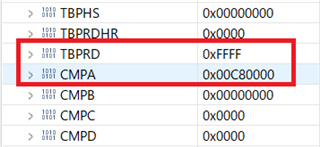
在代码中、PWM8用于同步 SDFM、其对应的注册表值如下:
您可能会使 PWM1和 PWM8混乱、因为我使用 PWM1来提供10MHz 时钟、因此 PWM1.TBPRD=4。
谢谢、
Jiakai
您好、Jaikai、
很抱歉我错过了该部件。 感谢您的突出显示。 我目前正在对此进行研究。
此外、我在示例代码中执行初始化之后提供的等待函数、该函数在您的示例代码中缺失。 您能否添加并在我返回给您时进行检查?
while((HWREGH(pwmInstance + EPWM_O_TBCTR)) < 550);
Aditya
您好、Aditya、
我已将其添加到 main()函数中,如下所示:
SDFM_DisableInterrupt (SDFM1_base、SDFM_FILTER_1、
(SDFM_HIGH_LEVEL_THRESHOLD_INTERRUPT |
SDFM_LOW_LEVEL_THRESHOLD_INTERRUPT));
while (((HWREGH (EPWM8_BASE + EPWM_O_TBCTR))< 550);
//
//启用主中断,以便可以触发任何过滤器中断
//通过 SDFM 中断到 CPU
//
SDFM_enableMasterInterrupt (SDFM1_base);
多次运行代码、未找到差异。
谢谢、
Jiakai
Jaikai、
请给我一些时间来思考这个问题。
谢谢、
Aditya
Aditya、
别着急,慢慢来。
谢谢、
Jiakai
您好、Jaikai、
很抱歉耽误你的答复。 我看到您已禁用负责在代码中生成 SDSYNC 信号的 ePWM SOCA。 请参阅参考手册中的方框图、了解来自 PWM 的 SDSYNC 信号的路径。
这可能是您的 EPWM SDSYNC 信号未到达 SDFM 模块的原因之一。 您可以更新您的代码吗?
谢谢、
Aditya
您好、Aditya、
我想您刚才谈到的是、我在第212行中评论了函数调用。
如前所述、当我使用 SDFM_enableWaitForSync 启用时
SYNC 信号、程序不会进入中断例程 sdfmFIFO1ISR。
谢谢、
Jiakai
Jiakai、您好!
TBPRD 0xFFFF 导致 TB 子模块设置 CTR_max 标志。 奇怪的是、TRM 不会说标志如何影响 TB 计数。 似乎 TBPRD 应加载0xFFFE (-1)以停止 CTR_max 计数溢出标志。
CTR_max 时基计数器等于最大值。 (TBCTR = 0xFFFF)
当 TBCTR 值达到其最大值时生成的事件。 该信号仅用作状态位????
您好、GI、
PWM8.TBPRD 用于提供 SOCA 信号来同步 SDFM 转换、其他事件将被忽略(我认为)。
我将 PWM8.TBPRD 设置为0XFFF0、但程序仍然无法进入中断。
谢谢、
Jiakai
您好!
我的意思是在定义 JAIKAI 宏后启用当前不属于代码一部分的 ADC SOC 信号。
#ifndef JIAKAI // // Configure SOCA signal // // EPWM_setADCTriggerSource(EPWM1_BASE, EPWM_SOC_A, EPWM_SOC_TBCTR_U_CMPA); EPWM_setADCTriggerEventPrescale(EPWM1_BASE, EPWM_SOC_A, 1); #endif
您可以取消注释这些行吗?
谢谢、
Aditya
您好、Aditya、
我未对代码进行注释(从 PWM1更改为 PWM8)、如下所示:
//#ifndef JIAKAI // // Configure SOCA signal // // EPWM_setADCTriggerSource(epwmInstance, EPWM_SOC_A, EPWM_SOC_TBCTR_U_CMPA); EPWM_setADCTriggerEventPrescale(epwmInstance, EPWM_SOC_A, 1); //#endif
但程序仍然无法进入中断例程 sdfmFIFO1ISR。
谢谢、
Jiakai
Jiakai、您好!
也许 INT CLEAR 应该放置在引导程序入口附近以停止重新进入。 建议在 INT 环路中进行 LED 切换、以便您可以查看它是否已打开/关闭。
//
//确认此中断以接收来自组5的更多中断
//
INTERRUPT_clearACKGROUP (INTERRUPT_ACK_group5);
//
//切换状态 LED
//
counterLED++;
if (counterLED >(uint32_t)(USER_ISR_FREQ_Hz / LED_BLINK FREQ_Hz)
{
HAL_TOGLELED (halHandle、HAL_GPIO_LED2);
counterLED = 0;
}
BTW:在 ePWM 配置中、我没有看到启用 ADC 触发源的调用。 首先禁用 SOC_A 中断、以便在配置 SOC_A 时不会触发错误触发
您好、GI、
在中断例程中、以下代码用于避免重新进入:
关于启用 SOCA 事件代码、如下所示(Aditya 也提到了它):
源代码如下所示供您查看:
//########################################################################### // // FILE: sdfm_ex5_filter_sync_fifo_cpuread.c // // TITLE: SDFM Type 1 Filter FIFO Example. // //! \addtogroup driver_example_list //! <h1> SDFM Type 1 Filter FIFO </h1> //! //! This example configures SDFM1 filter to demonstrate data read through //! CPU in FIFO & non-FIFO mode. Data filter is configured in mode 0 //! to select SINC3 filter with OSR of 256. Filter output is configured //! for 16-bit format and data shift of 10 is used. //! //! This example demonstrates the FIFO usage if enabled. FIFO length is set //! at 16 and data ready interrupt is configured to be triggered when FIFO is //! full. In this example, SDFM filter data is read by CPU in SDFM Data Ready //! ISR routine. //! //! \b External \b Connections \n //! Connect Sigma-Delta streams to (SD-D1, SD-C1 to SD-D4,SD-C4) //! on GPIO24-GPIO31 //! //! \b Watch \b Variables \n //! - \b filter1Result - Output of filter 1 //! // //########################################################################### // $TI Release: F28004x Support Library v1.09.00.00 $ // $Release Date: Thu Mar 19 07:26:52 IST 2020 $ // $Copyright: // Copyright (C) 2020 Texas Instruments Incorporated - http://www.ti.com/ // // Redistribution and use in source and binary forms, with or without // modification, are permitted provided that the following conditions // are met: // // Redistributions of source code must retain the above copyright // notice, this list of conditions and the following disclaimer. // // Redistributions in binary form must reproduce the above copyright // notice, this list of conditions and the following disclaimer in the // documentation and/or other materials provided with the // distribution. // // Neither the name of Texas Instruments Incorporated nor the names of // its contributors may be used to endorse or promote products derived // from this software without specific prior written permission. // // THIS SOFTWARE IS PROVIDED BY THE COPYRIGHT HOLDERS AND CONTRIBUTORS // "AS IS" AND ANY EXPRESS OR IMPLIED WARRANTIES, INCLUDING, BUT NOT // LIMITED TO, THE IMPLIED WARRANTIES OF MERCHANTABILITY AND FITNESS FOR // A PARTICULAR PURPOSE ARE DISCLAIMED. IN NO EVENT SHALL THE COPYRIGHT // OWNER OR CONTRIBUTORS BE LIABLE FOR ANY DIRECT, INDIRECT, INCIDENTAL, // SPECIAL, EXEMPLARY, OR CONSEQUENTIAL DAMAGES (INCLUDING, BUT NOT // LIMITED TO, PROCUREMENT OF SUBSTITUTE GOODS OR SERVICES; LOSS OF USE, // DATA, OR PROFITS; OR BUSINESS INTERRUPTION) HOWEVER CAUSED AND ON ANY // THEORY OF LIABILITY, WHETHER IN CONTRACT, STRICT LIABILITY, OR TORT // (INCLUDING NEGLIGENCE OR OTHERWISE) ARISING IN ANY WAY OUT OF THE USE // OF THIS SOFTWARE, EVEN IF ADVISED OF THE POSSIBILITY OF SUCH DAMAGE. // $ //########################################################################### // // Included Files // #include "driverlib.h" #include "device.h" #include <stdio.h> #define JIAKAI // // Defines // #define MAX_SAMPLES 1024 #define FIFO_INT_NUM 2U #define SDFM_FILTER_ENABLE 0x2U // // Macro to enable FIFO mode. Make it zero to disable // FIFO mode. // #define ENABLE_FIFO 1 // // Globals // int16_t filter1Result[MAX_SAMPLES]; #pragma DATA_SECTION(filter1Result, "Filter1_RegsFile"); // // Function Prototypes // void configureSDFMPins(void); void initEPWM(uint32_t epwmInstance); // // ISRs // __interrupt void sdfmFIFO1ISR(void); __interrupt void sdfm1ErrorISR(void); // // Main // void main(void) { // // Initialize device clock and peripherals // Device_init(); // // Setup GPIO by disabling pin locks and enabling pullups // Device_initGPIO(); // // Initialize PIE and clear PIE registers. Disables CPU interrupts. // Interrupt_initModule(); // // Initialize the PIE vector table with pointers to the shell Interrupt // Service Routines (ISR). // Interrupt_initVectorTable(); // // Interrupts that are used in this example are re-mapped to // ISR functions found within this file. // Interrupt_clearACKGroup(INTERRUPT_ACK_GROUP5); Interrupt_register(INT_SDFM1DR1, sdfmFIFO1ISR); Interrupt_register(INT_SDFM1, sdfm1ErrorISR); // // Enable SDFM1 interrupts(Data Ready & Error interrupts) // Interrupt_enableMaster(); Interrupt_enable(INT_SDFM1DR1); Interrupt_enable(INT_SDFM1); initEPWM(EPWM8_BASE); // // Configure GPIO pins as SDFM pins // configureSDFMPins(); // // Input Control Unit // // Configure Input Control Unit: Modulator Clock rate = Modulator data rate // SDFM_setupModulatorClock(SDFM1_BASE, SDFM_FILTER_1, SDFM_MODULATOR_CLK_EQUAL_DATA_RATE); // // Data Filter Unit // // Configure Data Filter Unit - filter type, OSR value and // enable / disable data filter // SDFM_configDataFilter(SDFM1_BASE, (SDFM_FILTER_1 | SDFM_FILTER_SINC_3 | SDFM_SET_OSR(256)), (SDFM_DATA_FORMAT_16_BIT | SDFM_FILTER_ENABLE | SDFM_SHIFT_VALUE(0x000A))); #if (ENABLE_FIFO) // // Set data ready interrupt source as fifo interrupt // SDFM_setDataReadyInterruptSource(SDFM1_BASE, SDFM_FILTER_1, SDFM_DATA_READY_SOURCE_FIFO); // // Enable FIFO and set the FIFO interrupt level // SDFM_enableFIFOBuffer(SDFM1_BASE, SDFM_FILTER_1); SDFM_setFIFOInterruptLevel(SDFM1_BASE, SDFM_FILTER_1, FIFO_INT_NUM); SDFM_enableInterrupt(SDFM1_BASE, SDFM_FILTER_1, (SDFM_FIFO_INTERRUPT | SDFM_FIFO_OVERFLOW_INTERRUPT)); #else // // Set data ready interrupt source as fifo interrupt // SDFM_setDataReadyInterruptSource(SDFM1_BASE, SDFM_FILTER_1, SDFM_DATA_READY_SOURCE_DIRECT); SDFM_enableInterrupt(SDFM1_BASE, SDFM_FILTER_1, SDFM_DATA_FILTER_ACKNOWLEDGE_INTERRUPT); #endif // // Enable Master filter bit: Unless this bit is set none of the filter // modules can be enabled. All the filter modules are synchronized when // master filter bit is enabled after individual filter modules are enabled. // SDFM_enableMasterFilter(SDFM1_BASE); // // Use PWM8.CMPA signals to synchronize the filters. // #if (0) SDFM_disableExternalReset(SDFM1_BASE, SDFM_FILTER_1); #else SDFM_enableExternalReset(SDFM1_BASE, SDFM_FILTER_1); SDFM_setPWMSyncSource(SDFM1_BASE, SDFM_FILTER_1, SDFM_SYNC_PWM8_SOCA); SDFM_enableWaitForSync(SDFM1_BASE, SDFM_FILTER_1); #endif // // Enable modulator failure interrupt, disable threshold interrupts // SDFM_enableInterrupt(SDFM1_BASE, SDFM_FILTER_1, SDFM_MODULATOR_FAILURE_INTERRUPT); SDFM_disableInterrupt(SDFM1_BASE, SDFM_FILTER_1, (SDFM_HIGH_LEVEL_THRESHOLD_INTERRUPT | SDFM_LOW_LEVEL_THRESHOLD_INTERRUPT)); while((HWREGH(EPWM8_BASE + EPWM_O_TBCTR)) < 550); // // Enable master interrupt so that any of the filter interrupts can trigger // by SDFM interrupt to CPU // SDFM_enableMasterInterrupt(SDFM1_BASE); // // Enable Global Interrupt (INTM) and realtime interrupt (DBGM) // EINT; ERTM; // // Wait for an interrupt // while(1); } // // sdfm1ErrorISR - SDFM1 Error ISR // __interrupt void sdfm1ErrorISR(void) { // // Clear SDFM flag register (SDIFLG) // SDFM_clearInterruptFlag(SDFM1_BASE, SDFM_MASTER_INTERRUPT_FLAG | 0xFFFF); // // Acknowledge this interrupt to receive more interrupts from group 5 // Interrupt_clearACKGroup(INTERRUPT_ACK_GROUP5); } #define PWM_TBCTR(_p) *((uint16_t *)(0x3F04 + 0x100 * (_p))) int index = 0; uint16_t tmBuf[100]; // // sdfmFIFO1ISR - SDFM FIFO1 ISR // __interrupt void sdfmFIFO1ISR(void) { uint16_t i; static uint16_t loopCounter1 = 0; #if (0) SDFM_setOutputDataFormat(SDFM1_BASE, SDFM_FILTER_1, SDFM_DATA_FORMAT_16_BIT); #endif // // Read SDFM flag register (SDIFLG) // if(loopCounter1 >= MAX_SAMPLES) { ESTOP0; } else if(SDFM_getFIFOISRStatus(SDFM1_BASE, SDFM_FILTER_1) == 0x1U) { tmBuf[index] = PWM_TBCTR(8); if (++index >= 100) index = 0; for(i = 0; i < FIFO_INT_NUM; i++) { filter1Result[loopCounter1++] = (int16_t)(SDFM_getFIFOData(SDFM1_BASE, SDFM_FILTER_1) >> 16U); } } else if(SDFM_getNewFilterDataStatus(SDFM1_BASE, SDFM_FILTER_1) == 0x1U) { filter1Result[loopCounter1++] = (int16_t)(SDFM_getFilterData(SDFM1_BASE, SDFM_FILTER_1) >> 16U); } // // Clear SDFM flag register (SDIFLG) // SDFM_clearInterruptFlag(SDFM1_BASE, SDFM_MASTER_INTERRUPT_FLAG | SDFM_FILTER_1_FIFO_INTERRUPT_FLAG | SDFM_FILTER_1_NEW_DATA_FLAG | SDFM_FILTER_1_FIFO_OVERFLOW_FLAG); // // Acknowledge this interrupt to receive more interrupts from group 5 // Interrupt_clearACKGroup(INTERRUPT_ACK_GROUP5); } // // configureSDFMPins - Configure SDFM GPIOs // void configureSDFMPins(void) { uint16_t pin; #ifdef JIAKAI for(pin = 16; pin <= 17; pin++) { // GPIO_setDirectionMode(pin, GPIO_DIR_MODE_IN); GPIO_setMasterCore(pin, GPIO_CORE_CPU1); GPIO_setPadConfig(pin, GPIO_PIN_TYPE_STD); GPIO_setQualificationMode(pin, GPIO_QUAL_ASYNC); } GPIO_setPinConfig(GPIO_16_SD_D1); GPIO_setPinConfig(GPIO_17_SD_C1); #else for(pin = 24; pin <= 31; pin++) { GPIO_setDirectionMode(pin, GPIO_DIR_MODE_IN); GPIO_setMasterCore(pin, GPIO_CORE_CPU1); GPIO_setPadConfig(pin, GPIO_PIN_TYPE_STD); GPIO_setQualificationMode(pin, GPIO_QUAL_ASYNC); } // // Configure GPIO16-GPIO31 as SDFM pins // GPIO_setPinConfig(GPIO_24_SD_D1); GPIO_setPinConfig(GPIO_25_SD_C1); GPIO_setPinConfig(GPIO_26_SD_D2); GPIO_setPinConfig(GPIO_27_SD_C2); GPIO_setPinConfig(GPIO_28_SD_D3); GPIO_setPinConfig(GPIO_29_SD_C3); GPIO_setPinConfig(GPIO_30_SD_D4); GPIO_setPinConfig(GPIO_31_SD_C4); #endif } // // initEPWM - Initialize specified EPWM settings // void initEPWM(uint32_t epwmInstance) { // // Disable sync(Freeze clock to PWM as well) // SysCtl_disablePeripheral(SYSCTL_PERIPH_CLK_TBCLKSYNC); // // Setup TBCLK: Configure timer period = 801 TBCLKs, phase = 0 & // clear counter // EPWM_setTimeBasePeriod(epwmInstance, 0xFFF0); EPWM_setPhaseShift(epwmInstance, 0U); EPWM_setTimeBaseCounter(epwmInstance, 0U); // // Set CMPA value // EPWM_setCounterCompareValue(epwmInstance, EPWM_COUNTER_COMPARE_A, 200U); // // Setup counter mode // EPWM_setTimeBaseCounterMode(epwmInstance, EPWM_COUNTER_MODE_UP); EPWM_setClockPrescaler(epwmInstance, EPWM_CLOCK_DIVIDER_1, EPWM_HSCLOCK_DIVIDER_1); // // Set actions: // Toggle PWMxA on event A, up-count // Toggle PWMxB on event A, up-count // GPIO_setPadConfig(0, GPIO_PIN_TYPE_STD); GPIO_setPinConfig(GPIO_0_EPWM1A); GPIO_setPadConfig(1, GPIO_PIN_TYPE_STD); GPIO_setPinConfig(GPIO_1_EPWM1B); EPWM_setTimeBasePeriod(EPWM1_BASE, 4); // PWM1 period: 0.1us EPWM_setTimeBaseCounterMode(EPWM1_BASE, EPWM_COUNTER_MODE_UP); EPWM_setClockPrescaler(EPWM1_BASE, EPWM_CLOCK_DIVIDER_1, EPWM_HSCLOCK_DIVIDER_1); EPWM_setActionQualifierAction(EPWM1_BASE, EPWM_AQ_OUTPUT_A, EPWM_AQ_OUTPUT_TOGGLE, EPWM_AQ_OUTPUT_ON_TIMEBASE_PERIOD); // EPWM_AQ_OUTPUT_ON_TIMEBASE_UP_CMPA); EPWM_setActionQualifierAction(EPWM1_BASE, EPWM_AQ_OUTPUT_B, EPWM_AQ_OUTPUT_TOGGLE, EPWM_AQ_OUTPUT_ON_TIMEBASE_PERIOD); // EPWM_AQ_OUTPUT_ON_TIMEBASE_UP_CMPB); //#ifndef JIAKAI // // Configure SOCA signal // // EPWM_setADCTriggerSource(epwmInstance, EPWM_SOC_A, EPWM_SOC_TBCTR_U_CMPA); EPWM_setADCTriggerEventPrescale(epwmInstance, EPWM_SOC_A, 1); //#endif // // Enable sync and clock to PWM // SysCtl_enablePeripheral(SYSCTL_PERIPH_CLK_TBCLKSYNC); } // // End of file //
谢谢、
Jiakai
这是中断{__interrupt void sdfmFIFO1ISR (void)}将 ACK 上移至顶部,在进行多次调用后 ACK 位于底部。 我仍然不容易找到您在哪里或如果您启用了 SOC-A 触发器、只能看到您配置了触发源事件。
您好、GI、
正确、代码未启用 SOCA、我在下面添加了它、但在 CCS 上运行代码时仍然没有区别:
//#ifndef JIAKAI
//
//配置 SOCA 信号
//
//
ePWM_setADCTriggerSource (epwmInstance、ePWM_SOC_A、ePWM_SOC_TBCTR_U_CMPA);
ePWM_setADCTriggerEventPrescale (epwmInstance、ePWM_SOC_A、1);
ePWM_enableADCtrigger (epwmInstance、ePWM_SOC_A);
//#endif
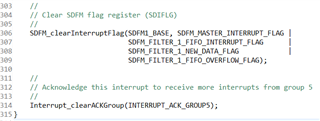
在中断例程 sdfmFIFO1ISR 中、 Interrupt_clearACKGroup (interrupt_ACK_group5)
函数调用是最后一条语句。 我认为可以、调用此函数是为了允许以下 SDFM 中断。
将其移到 ISR 顶部是可以的、但可能没有帮助(CPU 永远不会进入此 ISR)。
非常感谢!
Jiakai
您好、Jaikai、
我们能否验证一下、首先时钟输入是否正常? 如果您可以访问任何示波器、您是否可以将 PWM 输出连接到任何 GPIO 并验证预期的 PWM 是否出现?
此外、您的 SDFM 模块是否正确接收到来自 ePWM 模块的时钟信号? 您能否检查一次连接?
Aditya
如果没有 LED 切换、您可能永远不知道。 单步 CCS 调试我的不会触发 ADC 中断、具体取决于调试设置等 建议始终发出中断清除第一个调用来停止回绕、重新进入甚至可能导致 CPU 停止。
[引用 userid="111331" URL"~/support/microcontrollers/c2000-microcontrollers-group/c2000/f/c2000-microcontrollers-forum/1008118/tms320f280049c-the-problems-when-using-pwm-to-synchronize-sdfm/3736974 #3736974"](epwmInstance、ePWM_SOC_A、ePWM_SOC_TBCTR_U_CMPA);[/引用]是否为 CMPA 匹配计数配置/启用了动作限定符?
您好、Aditya、
我已经检查了 PWM1输出、它是一个10MHz 信号、如果 Sdfm 输入时钟未连接到、也是如此
时钟源 SDFM 将导致错误中断。
谢谢、
Jiakai
您好、GI、
我没有使用 LED 开/关来检查程序是否进入 ISR、但我确实使用 tmBuf 来保存 PWM8.TBCTR
当程序进入 ISR (在288行上)、但 tmBuf 保持全部为0。 我甚至把 tmBuf 移到 ISR 的开头
但内容不变。
谢谢、
Jiakai
Jaikai、
我在我的设置中重新创建了问题、并找到了 GI 突出显示的问题。 问题在于 EPWM8 SOCA 事件未生成、最终将停止 SDSYNC 事件生成。 因此、我们不会看到 CPU 进入 ISR。
在 EPWM 初始化内部、当进入时、您需要禁用 EPWM ADC 触发器、并在离开 EPWM 初始化块时将其重新启用。 只要我们需要使用来自 ePWM 模块的 ADC SOC 信号、就必须保持此流程。
连接初始化代码、这有助于我使代码正常工作。
// // initEPWM - Initialize specified EPWM settings // void initEPWM(uint32_t epwmInstance) { // // Disable sync(Freeze clock to PWM as well) // SysCtl_disablePeripheral(SYSCTL_PERIPH_CLK_TBCLKSYNC); EPWM_disableADCTrigger(EPWM8_BASE, EPWM_SOC_A); // // Setup TBCLK: Configure timer period = 801 TBCLKs, phase = 0 & // clear counter // EPWM_setTimeBasePeriod(epwmInstance, 0xFFF0); EPWM_setPhaseShift(epwmInstance, 0U); EPWM_setTimeBaseCounter(epwmInstance, 0U); // // Set CMPA value // EPWM_setCounterCompareValue(epwmInstance, EPWM_COUNTER_COMPARE_A, 200U); // // Setup counter mode // EPWM_setTimeBaseCounterMode(epwmInstance, EPWM_COUNTER_MODE_UP); EPWM_setClockPrescaler(epwmInstance, EPWM_CLOCK_DIVIDER_1, EPWM_HSCLOCK_DIVIDER_1); // // Set actions: // Toggle PWMxA on event A, up-count // Toggle PWMxB on event A, up-count // GPIO_setPadConfig(0, GPIO_PIN_TYPE_STD); GPIO_setPinConfig(GPIO_0_EPWM1A); GPIO_setPadConfig(1, GPIO_PIN_TYPE_STD); GPIO_setPinConfig(GPIO_1_EPWM1B); EPWM_setTimeBasePeriod(EPWM1_BASE, 4); // PWM1 period: 0.1us EPWM_setTimeBaseCounterMode(EPWM1_BASE, EPWM_COUNTER_MODE_UP); EPWM_setClockPrescaler(EPWM1_BASE, EPWM_CLOCK_DIVIDER_1, EPWM_HSCLOCK_DIVIDER_1); EPWM_setActionQualifierAction(EPWM1_BASE, EPWM_AQ_OUTPUT_A, EPWM_AQ_OUTPUT_TOGGLE, EPWM_AQ_OUTPUT_ON_TIMEBASE_PERIOD); // EPWM_AQ_OUTPUT_ON_TIMEBASE_UP_CMPA); EPWM_setActionQualifierAction(EPWM1_BASE, EPWM_AQ_OUTPUT_B, EPWM_AQ_OUTPUT_TOGGLE, EPWM_AQ_OUTPUT_ON_TIMEBASE_PERIOD); // EPWM_AQ_OUTPUT_ON_TIMEBASE_UP_CMPB); //#ifndef JIAKAI // // Configure SOCA signal // // // EPWM_setADCTriggerSource(EPWM1_BASE, EPWM_SOC_A, EPWM_SOC_TBCTR_U_CMPA); // EPWM_setADCTriggerEventPrescale(EPWM1_BASE, EPWM_SOC_A, 1); //#endif EPWM_setADCTriggerSource(EPWM8_BASE, EPWM_SOC_A, EPWM_SOC_TBCTR_U_CMPA); EPWM_setADCTriggerEventPrescale(EPWM8_BASE, EPWM_SOC_A, 1); // // Enable sync and clock to PWM // EPWM_enableADCTrigger(EPWM8_BASE, EPWM_SOC_A); SysCtl_enablePeripheral(SYSCTL_PERIPH_CLK_TBCLKSYNC); }
希望这对您有所帮助。
Aditya
您好、Aditya、
我在 函数 initEPWM 的开头(放置代码的位置)添加了 ePWM_disableADCTrigger、但仍然没有更改。
我已经检查了 PWM8.ETSEL.SOCAEN、在调用 ePWM_DisableADCTrigger 之前它是0。
我还认为在初始化 SDFM 之前、以下3个函数调用(启用 SDFM 中断)不是很好、
我将它们移动到所有器件都已初始化的位置、但结果仍然相同。
更改代码如下所示:
//########################################################################### // // FILE: sdfm_ex5_filter_sync_fifo_cpuread.c // // TITLE: SDFM Type 1 Filter FIFO Example. // //! \addtogroup driver_example_list //! <h1> SDFM Type 1 Filter FIFO </h1> //! //! This example configures SDFM1 filter to demonstrate data read through //! CPU in FIFO & non-FIFO mode. Data filter is configured in mode 0 //! to select SINC3 filter with OSR of 256. Filter output is configured //! for 16-bit format and data shift of 10 is used. //! //! This example demonstrates the FIFO usage if enabled. FIFO length is set //! at 16 and data ready interrupt is configured to be triggered when FIFO is //! full. In this example, SDFM filter data is read by CPU in SDFM Data Ready //! ISR routine. //! //! \b External \b Connections \n //! Connect Sigma-Delta streams to (SD-D1, SD-C1 to SD-D4,SD-C4) //! on GPIO24-GPIO31 //! //! \b Watch \b Variables \n //! - \b filter1Result - Output of filter 1 //! // //########################################################################### // $TI Release: F28004x Support Library v1.09.00.00 $ // $Release Date: Thu Mar 19 07:26:52 IST 2020 $ // $Copyright: // Copyright (C) 2020 Texas Instruments Incorporated - http://www.ti.com/ // // Redistribution and use in source and binary forms, with or without // modification, are permitted provided that the following conditions // are met: // // Redistributions of source code must retain the above copyright // notice, this list of conditions and the following disclaimer. // // Redistributions in binary form must reproduce the above copyright // notice, this list of conditions and the following disclaimer in the // documentation and/or other materials provided with the // distribution. // // Neither the name of Texas Instruments Incorporated nor the names of // its contributors may be used to endorse or promote products derived // from this software without specific prior written permission. // // THIS SOFTWARE IS PROVIDED BY THE COPYRIGHT HOLDERS AND CONTRIBUTORS // "AS IS" AND ANY EXPRESS OR IMPLIED WARRANTIES, INCLUDING, BUT NOT // LIMITED TO, THE IMPLIED WARRANTIES OF MERCHANTABILITY AND FITNESS FOR // A PARTICULAR PURPOSE ARE DISCLAIMED. IN NO EVENT SHALL THE COPYRIGHT // OWNER OR CONTRIBUTORS BE LIABLE FOR ANY DIRECT, INDIRECT, INCIDENTAL, // SPECIAL, EXEMPLARY, OR CONSEQUENTIAL DAMAGES (INCLUDING, BUT NOT // LIMITED TO, PROCUREMENT OF SUBSTITUTE GOODS OR SERVICES; LOSS OF USE, // DATA, OR PROFITS; OR BUSINESS INTERRUPTION) HOWEVER CAUSED AND ON ANY // THEORY OF LIABILITY, WHETHER IN CONTRACT, STRICT LIABILITY, OR TORT // (INCLUDING NEGLIGENCE OR OTHERWISE) ARISING IN ANY WAY OUT OF THE USE // OF THIS SOFTWARE, EVEN IF ADVISED OF THE POSSIBILITY OF SUCH DAMAGE. // $ //########################################################################### // // Included Files // #include "driverlib.h" #include "device.h" #include <stdio.h> #define JIAKAI // // Defines // #define MAX_SAMPLES 1024 #define FIFO_INT_NUM 2U #define SDFM_FILTER_ENABLE 0x2U // // Macro to enable FIFO mode. Make it zero to disable // FIFO mode. // #define ENABLE_FIFO 1 // // Globals // int16_t filter1Result[MAX_SAMPLES]; #pragma DATA_SECTION(filter1Result, "Filter1_RegsFile"); // // Function Prototypes // void configureSDFMPins(void); void initEPWM(uint32_t epwmInstance); // // ISRs // __interrupt void sdfmFIFO1ISR(void); __interrupt void sdfm1ErrorISR(void); // // Main // void main(void) { // // Initialize device clock and peripherals // Device_init(); // // Setup GPIO by disabling pin locks and enabling pullups // Device_initGPIO(); // // Initialize PIE and clear PIE registers. Disables CPU interrupts. // Interrupt_initModule(); // // Initialize the PIE vector table with pointers to the shell Interrupt // Service Routines (ISR). // Interrupt_initVectorTable(); // // Interrupts that are used in this example are re-mapped to // ISR functions found within this file. // Interrupt_clearACKGroup(INTERRUPT_ACK_GROUP5); Interrupt_register(INT_SDFM1DR1, sdfmFIFO1ISR); Interrupt_register(INT_SDFM1, sdfm1ErrorISR); // // Enable SDFM1 interrupts(Data Ready & Error interrupts) // #if (0) // need to move to the palce that all devices are initialized Interrupt_enableMaster(); Interrupt_enable(INT_SDFM1DR1); Interrupt_enable(INT_SDFM1); #endif initEPWM(EPWM8_BASE); // // Configure GPIO pins as SDFM pins // configureSDFMPins(); // // Input Control Unit // // Configure Input Control Unit: Modulator Clock rate = Modulator data rate // SDFM_setupModulatorClock(SDFM1_BASE, SDFM_FILTER_1, SDFM_MODULATOR_CLK_EQUAL_DATA_RATE); // // Data Filter Unit // // Configure Data Filter Unit - filter type, OSR value and // enable / disable data filter // SDFM_configDataFilter(SDFM1_BASE, (SDFM_FILTER_1 | SDFM_FILTER_SINC_3 | SDFM_SET_OSR(256)), (SDFM_DATA_FORMAT_16_BIT | SDFM_FILTER_ENABLE | SDFM_SHIFT_VALUE(0x000A))); #if (ENABLE_FIFO) // // Set data ready interrupt source as fifo interrupt // SDFM_setDataReadyInterruptSource(SDFM1_BASE, SDFM_FILTER_1, SDFM_DATA_READY_SOURCE_FIFO); // // Enable FIFO and set the FIFO interrupt level // SDFM_enableFIFOBuffer(SDFM1_BASE, SDFM_FILTER_1); SDFM_setFIFOInterruptLevel(SDFM1_BASE, SDFM_FILTER_1, FIFO_INT_NUM); SDFM_enableInterrupt(SDFM1_BASE, SDFM_FILTER_1, (SDFM_FIFO_INTERRUPT | SDFM_FIFO_OVERFLOW_INTERRUPT)); #else // // Set data ready interrupt source as fifo interrupt // SDFM_setDataReadyInterruptSource(SDFM1_BASE, SDFM_FILTER_1, SDFM_DATA_READY_SOURCE_DIRECT); SDFM_enableInterrupt(SDFM1_BASE, SDFM_FILTER_1, SDFM_DATA_FILTER_ACKNOWLEDGE_INTERRUPT); #endif // // Enable Master filter bit: Unless this bit is set none of the filter // modules can be enabled. All the filter modules are synchronized when // master filter bit is enabled after individual filter modules are enabled. // SDFM_enableMasterFilter(SDFM1_BASE); // // Use PWM8.CMPA signals to synchronize the filters. // #if (0) SDFM_disableExternalReset(SDFM1_BASE, SDFM_FILTER_1); #else SDFM_enableExternalReset(SDFM1_BASE, SDFM_FILTER_1); SDFM_setPWMSyncSource(SDFM1_BASE, SDFM_FILTER_1, SDFM_SYNC_PWM8_SOCA); SDFM_enableWaitForSync(SDFM1_BASE, SDFM_FILTER_1); #endif // // Enable modulator failure interrupt, disable threshold interrupts // SDFM_enableInterrupt(SDFM1_BASE, SDFM_FILTER_1, SDFM_MODULATOR_FAILURE_INTERRUPT); SDFM_disableInterrupt(SDFM1_BASE, SDFM_FILTER_1, (SDFM_HIGH_LEVEL_THRESHOLD_INTERRUPT | SDFM_LOW_LEVEL_THRESHOLD_INTERRUPT)); while((HWREGH(EPWM8_BASE + EPWM_O_TBCTR)) < 550); // // Enable master interrupt so that any of the filter interrupts can trigger // by SDFM interrupt to CPU // SDFM_enableMasterInterrupt(SDFM1_BASE); #if (1) // need to move to the palce that all devices are initialized Interrupt_enableMaster(); Interrupt_enable(INT_SDFM1DR1); Interrupt_enable(INT_SDFM1); #endif // // Enable Global Interrupt (INTM) and realtime interrupt (DBGM) // EINT; ERTM; // // Wait for an interrupt // while(1); } // // sdfm1ErrorISR - SDFM1 Error ISR // __interrupt void sdfm1ErrorISR(void) { // // Clear SDFM flag register (SDIFLG) // SDFM_clearInterruptFlag(SDFM1_BASE, SDFM_MASTER_INTERRUPT_FLAG | 0xFFFF); // // Acknowledge this interrupt to receive more interrupts from group 5 // Interrupt_clearACKGroup(INTERRUPT_ACK_GROUP5); } #define PWM_TBCTR(_p) *((uint16_t *)(0x3F04 + 0x100 * (_p))) int index = 0; uint16_t tmBuf[100]; // // sdfmFIFO1ISR - SDFM FIFO1 ISR // __interrupt void sdfmFIFO1ISR(void) { uint16_t i; static uint16_t loopCounter1 = 0; #if (0) SDFM_setOutputDataFormat(SDFM1_BASE, SDFM_FILTER_1, SDFM_DATA_FORMAT_16_BIT); #endif // // Read SDFM flag register (SDIFLG) // if(loopCounter1 >= MAX_SAMPLES) { ESTOP0; } else if(SDFM_getFIFOISRStatus(SDFM1_BASE, SDFM_FILTER_1) == 0x1U) { tmBuf[index] = PWM_TBCTR(8); if (++index >= 100) index = 0; for(i = 0; i < FIFO_INT_NUM; i++) { filter1Result[loopCounter1++] = (int16_t)(SDFM_getFIFOData(SDFM1_BASE, SDFM_FILTER_1) >> 16U); } } else if(SDFM_getNewFilterDataStatus(SDFM1_BASE, SDFM_FILTER_1) == 0x1U) { filter1Result[loopCounter1++] = (int16_t)(SDFM_getFilterData(SDFM1_BASE, SDFM_FILTER_1) >> 16U); } // // Clear SDFM flag register (SDIFLG) // SDFM_clearInterruptFlag(SDFM1_BASE, SDFM_MASTER_INTERRUPT_FLAG | SDFM_FILTER_1_FIFO_INTERRUPT_FLAG | SDFM_FILTER_1_NEW_DATA_FLAG | SDFM_FILTER_1_FIFO_OVERFLOW_FLAG); // // Acknowledge this interrupt to receive more interrupts from group 5 // Interrupt_clearACKGroup(INTERRUPT_ACK_GROUP5); } // // configureSDFMPins - Configure SDFM GPIOs // void configureSDFMPins(void) { uint16_t pin; #ifdef JIAKAI for(pin = 16; pin <= 17; pin++) { // GPIO_setDirectionMode(pin, GPIO_DIR_MODE_IN); GPIO_setMasterCore(pin, GPIO_CORE_CPU1); GPIO_setPadConfig(pin, GPIO_PIN_TYPE_STD); GPIO_setQualificationMode(pin, GPIO_QUAL_ASYNC); } GPIO_setPinConfig(GPIO_16_SD_D1); GPIO_setPinConfig(GPIO_17_SD_C1); #else for(pin = 24; pin <= 31; pin++) { GPIO_setDirectionMode(pin, GPIO_DIR_MODE_IN); GPIO_setMasterCore(pin, GPIO_CORE_CPU1); GPIO_setPadConfig(pin, GPIO_PIN_TYPE_STD); GPIO_setQualificationMode(pin, GPIO_QUAL_ASYNC); } // // Configure GPIO16-GPIO31 as SDFM pins // GPIO_setPinConfig(GPIO_24_SD_D1); GPIO_setPinConfig(GPIO_25_SD_C1); GPIO_setPinConfig(GPIO_26_SD_D2); GPIO_setPinConfig(GPIO_27_SD_C2); GPIO_setPinConfig(GPIO_28_SD_D3); GPIO_setPinConfig(GPIO_29_SD_C3); GPIO_setPinConfig(GPIO_30_SD_D4); GPIO_setPinConfig(GPIO_31_SD_C4); #endif } // // initEPWM - Initialize specified EPWM settings // void initEPWM(uint32_t epwmInstance) { // // Disable sync(Freeze clock to PWM as well) // SysCtl_disablePeripheral(SYSCTL_PERIPH_CLK_TBCLKSYNC); EPWM_disableADCTrigger(epwmInstance, EPWM_SOC_A); // // Setup TBCLK: Configure timer period = 801 TBCLKs, phase = 0 & // clear counter // EPWM_setTimeBasePeriod(epwmInstance, 0xFFF0); EPWM_setPhaseShift(epwmInstance, 0U); EPWM_setTimeBaseCounter(epwmInstance, 0U); // // Set CMPA value // EPWM_setCounterCompareValue(epwmInstance, EPWM_COUNTER_COMPARE_A, 200U); // // Setup counter mode // EPWM_setTimeBaseCounterMode(epwmInstance, EPWM_COUNTER_MODE_UP); EPWM_setClockPrescaler(epwmInstance, EPWM_CLOCK_DIVIDER_1, EPWM_HSCLOCK_DIVIDER_1); // // Set actions: // Toggle PWMxA on event A, up-count // Toggle PWMxB on event A, up-count // GPIO_setPadConfig(0, GPIO_PIN_TYPE_STD); GPIO_setPinConfig(GPIO_0_EPWM1A); GPIO_setPadConfig(1, GPIO_PIN_TYPE_STD); GPIO_setPinConfig(GPIO_1_EPWM1B); EPWM_setTimeBasePeriod(EPWM1_BASE, 4); // PWM1 period: 0.1us EPWM_setTimeBaseCounterMode(EPWM1_BASE, EPWM_COUNTER_MODE_UP); EPWM_setClockPrescaler(EPWM1_BASE, EPWM_CLOCK_DIVIDER_1, EPWM_HSCLOCK_DIVIDER_1); EPWM_setActionQualifierAction(EPWM1_BASE, EPWM_AQ_OUTPUT_A, EPWM_AQ_OUTPUT_TOGGLE, EPWM_AQ_OUTPUT_ON_TIMEBASE_PERIOD); // EPWM_AQ_OUTPUT_ON_TIMEBASE_UP_CMPA); EPWM_setActionQualifierAction(EPWM1_BASE, EPWM_AQ_OUTPUT_B, EPWM_AQ_OUTPUT_TOGGLE, EPWM_AQ_OUTPUT_ON_TIMEBASE_PERIOD); // EPWM_AQ_OUTPUT_ON_TIMEBASE_UP_CMPB); //#ifndef JIAKAI // // Configure SOCA signal // // EPWM_setADCTriggerSource(epwmInstance, EPWM_SOC_A, EPWM_SOC_TBCTR_U_CMPA); EPWM_setADCTriggerEventPrescale(epwmInstance, EPWM_SOC_A, 1); EPWM_enableADCTrigger(epwmInstance, EPWM_SOC_A); //#endif // // Enable sync and clock to PWM // SysCtl_enablePeripheral(SYSCTL_PERIPH_CLK_TBCLKSYNC); } // // End of file //
谢谢、
Jiakai
Jaikai、
使用您发送的代码、我能够看到 CPU 进入 sdfmFIFO1ISR、 并且 EPwm8Regs.ETFlG.SOCA 变为高电平。 您能否在结束时再次检查一次?
如果无法解决、您能否共享压缩的项目? 我可以检查任何链接文件中的差异。
Aditya
您好、Aditya、
我没有创建项目、只需更改 C2000ware 项目中的 sdfm_ex5_filter_sync_fifo_cpuread.c 文件、路径如下:
C:\ti\c2000Ware_3_02_00_00\driverlib\f28004x\examples\sdfm\sdfm_ex5_filter_sync_fifo_cpuread.c
谢谢、
Jiakai
您好、Jaikai、
您能否安装最新的 C2000Ware 并尝试运行您的项目? 某些错误修复可能会帮助您的最终代码正常工作。 我在 C2000Ware_3_04版本上运行了示例代码。
下载 C2000Ware 的链接: C2000WARE 软件开发套件(SDK)|德州仪器 TI.com
谢谢、
Aditya
您好、Aditya、
我有 C2000Ware_3_04、因为我的 CCS 是 v9、它无法打开 C2000Ware_3_04项目、
因此我使用 C2000Ware_3_02项目。
我已经在 两个版本中比较了 sdfm_ex5_filter_sync_fifo_cpuread.c、没有区别
在 CPU 器件初始化代码中、唯一的区别是 2000Ware_3_04 更改了 SDFM 引脚配置
名称。
我将安装最新的 CCS 以进行确认。
谢谢、
Jiakai
您好、Jaikai、
很抱歉您遇到问题。 更改不仅仅是针对源代码。 我认为、辅助驾驶员可能会导致一些问题。 您共享的源代码在我的末尾运行得非常好
Aditya
如果将更新的 driverlib 导入到现有工程中是根本原因、则看起来会更容易。 导入高级选项"仅创建源链接"而不是导入整个库文件似乎是一个很好的解决方法。
Jaikai、
我尝试在 C2000Ware_3_02版本上运行该代码、它也可以在那里运行。 我可以看到代码在 sdfmFIFO1ISR 内部停止。
您是否能够在最终取得任何成功?
Aditya
您好、Aditya 和 GI、
由于 GI 的建议对我来说很容易、因此我将项目更改为将 C2000Ware 转换为 v3.4。
当我运行项目时、程序仅输入 sdfm1ErrorISR、从未输入 sdfmFIFO1ISR。
我很匆忙地解决了问题、因此我安装了 CCS v10.3.1和最新的 C200Ware。
我在 CCS v10.3.1上运行该程序、但仍然存在与在另一台计算机上相同的问题。
我设置2个计数器:cntErr 和 cntDat、cntErr 用于计算进入 sdfm1ErrorISR 的次数、
cntDat 用于对进入 sdfmFIFO1ISR 的时间进行计数。 运行几秒钟后、2个计数器值如下所示:
源代码如下:
//########################################################################### // // FILE: sdfm.h // // TITLE: C28x SDFM Driver // //########################################################################### // $TI Release: F28004x Support Library v1.12.00.00 $ // $Release Date: Fri Feb 12 18:57:27 IST 2021 $ // $Copyright: // Copyright (C) 2021 Texas Instruments Incorporated - http://www.ti.com/ // // Redistribution and use in source and binary forms, with or without // modification, are permitted provided that the following conditions // are met: // // Redistributions of source code must retain the above copyright // notice, this list of conditions and the following disclaimer. // // Redistributions in binary form must reproduce the above copyright // notice, this list of conditions and the following disclaimer in the // documentation and/or other materials provided with the // distribution. // // Neither the name of Texas Instruments Incorporated nor the names of // its contributors may be used to endorse or promote products derived // from this software without specific prior written permission. // // THIS SOFTWARE IS PROVIDED BY THE COPYRIGHT HOLDERS AND CONTRIBUTORS // "AS IS" AND ANY EXPRESS OR IMPLIED WARRANTIES, INCLUDING, BUT NOT // LIMITED TO, THE IMPLIED WARRANTIES OF MERCHANTABILITY AND FITNESS FOR // A PARTICULAR PURPOSE ARE DISCLAIMED. IN NO EVENT SHALL THE COPYRIGHT // OWNER OR CONTRIBUTORS BE LIABLE FOR ANY DIRECT, INDIRECT, INCIDENTAL, // SPECIAL, EXEMPLARY, OR CONSEQUENTIAL DAMAGES (INCLUDING, BUT NOT // LIMITED TO, PROCUREMENT OF SUBSTITUTE GOODS OR SERVICES; LOSS OF USE, // DATA, OR PROFITS; OR BUSINESS INTERRUPTION) HOWEVER CAUSED AND ON ANY // THEORY OF LIABILITY, WHETHER IN CONTRACT, STRICT LIABILITY, OR TORT // (INCLUDING NEGLIGENCE OR OTHERWISE) ARISING IN ANY WAY OUT OF THE USE // OF THIS SOFTWARE, EVEN IF ADVISED OF THE POSSIBILITY OF SUCH DAMAGE. // $ //########################################################################### #ifndef SDFM_H #define SDFM_H //***************************************************************************** // // If building with a C++ compiler, make all of the definitions in this header // have a C binding. // //***************************************************************************** #ifdef __cplusplus extern "C" { #endif //***************************************************************************** // //! \addtogroup sdfm_api SDFM //! @{ // //***************************************************************************** #include <stdbool.h> #include <stdint.h> #include "inc/hw_types.h" #include "inc/hw_sdfm.h" #include "inc/hw_memmap.h" #include "cpu.h" #include "debug.h" //***************************************************************************** // // Defines for the API. // //***************************************************************************** //! Macro to get the low threshold //! #define SDFM_GET_LOW_THRESHOLD(C) ((uint16_t)(C)) //! Macro to get the high threshold //! #define SDFM_GET_HIGH_THRESHOLD(C) ((uint16_t)((uint32_t)(C) >> 16U)) //! Macro to convert comparator over sampling ratio to acceptable bit location //! #define SDFM_SET_OSR(X) (((X) - 1) << 8U) //! Macro to convert the data shift bit values to acceptable bit location //! #define SDFM_SHIFT_VALUE(X) ((X) << 2U) //! Macro to combine high threshold and low threshold values //! #define SDFM_THRESHOLD(H, L) ((((uint32_t)(H)) << 16U) | (L)) //! Macro to set the FIFO level to acceptable bit location //! #define SDFM_SET_FIFO_LEVEL(X) ((X) << 7U) //! Macro to set and enable the zero cross threshold value. //! #define SDFM_SET_ZERO_CROSS_THRESH_VALUE(X) (0x8000 | (X)) //! Macros to enable or disable filter. //! #define SDFM_FILTER_DISABLE 0x0U #define SDFM_FILTER_ENABLE 0x2U //***************************************************************************** // //! Values that can be returned from SDFM_getThresholdStatus() // //***************************************************************************** typedef enum { SDFM_OUTPUT_WITHIN_THRESHOLD = 0, //!< SDFM output is within threshold SDFM_OUTPUT_ABOVE_THRESHOLD = 1, //!< SDFM output is above threshold SDFM_OUTPUT_BELOW_THRESHOLD = 2 //!< SDFM output is below threshold } SDFM_OutputThresholdStatus; //***************************************************************************** // //! Values that can be passed to all functions as the \e filterNumber //! parameter. // //***************************************************************************** typedef enum { SDFM_FILTER_1 = 0, //!< Digital filter 1 SDFM_FILTER_2 = 1, //!< Digital filter 2 SDFM_FILTER_3 = 2, //!< Digital filter 3 SDFM_FILTER_4 = 3 //!< Digital filter 4 } SDFM_FilterNumber; //***************************************************************************** // //! Values that can be passed to SDFM_setFilterType(), //! SDFM_setComparatorFilterType() as the \e filterType parameter. // //***************************************************************************** typedef enum { //! Digital filter with SincFast structure. SDFM_FILTER_SINC_FAST = 0x00, //! Digital filter with Sinc1 structure SDFM_FILTER_SINC_1 = 0x10, //! Digital filter with Sinc3 structure. SDFM_FILTER_SINC_2 = 0x20, //! Digital filter with Sinc4 structure. SDFM_FILTER_SINC_3 = 0x30 } SDFM_FilterType; //***************************************************************************** // //! Values that can be passed to SDFM_setupModulatorClock(),as the //! \e clockMode parameter. // //***************************************************************************** typedef enum { //! Modulator clock is identical to the data rate SDFM_MODULATOR_CLK_EQUAL_DATA_RATE = 0, //! Modulator clock is half the data rate SDFM_MODULATOR_CLK_HALF_DATA_RATE = 1, //! Modulator clock is off. Data is Manchester coded. SDFM_MODULATOR_CLK_OFF = 2, //! Modulator clock is double the data rate. SDFM_MODULATOR_CLK_DOUBLE_DATA_RATE = 3 } SDFM_ModulatorClockMode; //***************************************************************************** // //! Values that can be passed to SDFM_setOutputDataFormat(),as the //! \e dataFormat parameter. // //***************************************************************************** typedef enum { //! Filter output is in 16 bits 2's complement format. SDFM_DATA_FORMAT_16_BIT = 0, //! Filter output is in 32 bits 2's complement format. SDFM_DATA_FORMAT_32_BIT = 1 } SDFM_OutputDataFormat; //***************************************************************************** // //! Values that can be passed to SDFM_setDataReadyInterruptSource(),as the //! \e dataReadySource parameter. // //***************************************************************************** typedef enum { //! Data ready interrupt source is direct (non -FIFO). SDFM_DATA_READY_SOURCE_DIRECT = 0, //! Data ready interrupt source is FIFO. SDFM_DATA_READY_SOURCE_FIFO = 1 } SDFM_DataReadyInterruptSource; //***************************************************************************** // //! Values that can be passed to SDFM_setPWMSyncSource(),as the //! \e syncSource parameter. // //***************************************************************************** typedef enum { SDFM_SYNC_PWM1_SOCA = 0, //!< SDFM sync source is PWM1 SOCA SDFM_SYNC_PWM1_SOCB = 1, //!< SDFM sync source is PWM1 SOCB SDFM_SYNC_PWM2_SOCA = 4, //!< SDFM sync source is PWM2 SOCA SDFM_SYNC_PWM2_SOCB = 5, //!< SDFM sync source is PWM2 SOCB SDFM_SYNC_PWM3_SOCA = 8, //!< SDFM sync source is PWM3 SOCA SDFM_SYNC_PWM3_SOCB = 9, //!< SDFM sync source is PWM3 SOCB SDFM_SYNC_PWM4_SOCA = 12, //!< SDFM sync source is PWM4 SOCA SDFM_SYNC_PWM4_SOCB = 13, //!< SDFM sync source is PWM4 SOCB SDFM_SYNC_PWM5_SOCA = 16, //!< SDFM sync source is PWM5 SOCA SDFM_SYNC_PWM5_SOCB = 17, //!< SDFM sync source is PWM5 SOCB SDFM_SYNC_PWM6_SOCA = 20, //!< SDFM sync source is PWM6 SOCA SDFM_SYNC_PWM6_SOCB = 21, //!< SDFM sync source is PWM6 SOCB SDFM_SYNC_PWM7_SOCA = 24, //!< SDFM sync source is PWM7 SOCA SDFM_SYNC_PWM7_SOCB = 25, //!< SDFM sync source is PWM7 SOCB SDFM_SYNC_PWM8_SOCA = 28, //!< SDFM sync source is PWM8 SOCA SDFM_SYNC_PWM8_SOCB = 29 //!< SDFM sync source is PWM8 SOCB } SDFM_PWMSyncSource; //***************************************************************************** // //! Values that can be passed to SDFM_setFIFOClearOnSyncMode(),as the //! \e fifoClearSyncMode parameter. // //***************************************************************************** typedef enum { //! SDFM FIFO buffer is not cleared on Sync signal SDFM_FIFO_NOT_CLEARED_ON_SYNC = 0, //! SDFM FIFO buffer is cleared on Sync signal SDFM_FIFO_CLEARED_ON_SYNC = 1 } SDFM_FIFOClearSyncMode; //***************************************************************************** // //! Values that can be passed to SDFM_setWaitForSyncClearMode(),as the //! \e syncClearMode parameter. // //***************************************************************************** typedef enum { //! Wait for sync cleared using software. SDFM_MANUAL_CLEAR_WAIT_FOR_SYNC = 0, //! Wait for sync cleared automatically SDFM_AUTO_CLEAR_WAIT_FOR_SYNC = 1 } SDFM_WaitForSyncClearMode; //***************************************************************************** // // Values that can be passed to SDFM_enableInterrupt and SDFM_disableInterrupt // as intFlags parameter // //***************************************************************************** //! Interrupt is generated if Modulator fails. //! #define SDFM_MODULATOR_FAILURE_INTERRUPT 0x200U //! Interrupt on Comparator low-level threshold. //! #define SDFM_LOW_LEVEL_THRESHOLD_INTERRUPT 0x40U //! Interrupt on Comparator high-level threshold. //! #define SDFM_HIGH_LEVEL_THRESHOLD_INTERRUPT 0x20U //! Interrupt on Acknowledge flag //! #define SDFM_DATA_FILTER_ACKNOWLEDGE_INTERRUPT 0x1U //! Interrupt on FIFO level //! #define SDFM_FIFO_INTERRUPT 0x1000U //! Interrupt on FIFO overflow //! #define SDFM_FIFO_OVERFLOW_INTERRUPT 0x8000U //***************************************************************************** // // Values that can be passed to SDFM_clearInterruptFlag flags parameter // //***************************************************************************** //! Master interrupt flag //! #define SDFM_MASTER_INTERRUPT_FLAG 0x80000000U //! Filter 1 high -level threshold flag //! #define SDFM_FILTER_1_HIGH_THRESHOLD_FLAG 0x1U //! Filter 1 low -level threshold flag //! #define SDFM_FILTER_1_LOW_THRESHOLD_FLAG 0x2U //! Filter 2 high -level threshold flag //! #define SDFM_FILTER_2_HIGH_THRESHOLD_FLAG 0x4U //! Filter 2 low -level threshold flag //! #define SDFM_FILTER_2_LOW_THRESHOLD_FLAG 0x8U //! Filter 3 high -level threshold flag //! #define SDFM_FILTER_3_HIGH_THRESHOLD_FLAG 0x10U //! Filter 3 low -level threshold flag //! #define SDFM_FILTER_3_LOW_THRESHOLD_FLAG 0x20U //! Filter 4 high -level threshold flag //! #define SDFM_FILTER_4_HIGH_THRESHOLD_FLAG 0x40U //! Filter 4 low -level threshold flag //! #define SDFM_FILTER_4_LOW_THRESHOLD_FLAG 0x80U //! Filter 1 modulator failed flag //! #define SDFM_FILTER_1_MOD_FAILED_FLAG 0x100U //! Filter 2 modulator failed flag //! #define SDFM_FILTER_2_MOD_FAILED_FLAG 0x200U //! Filter 3 modulator failed flag //! #define SDFM_FILTER_3_MOD_FAILED_FLAG 0x400U //! Filter 4 modulator failed flag //! #define SDFM_FILTER_4_MOD_FAILED_FLAG 0x800U //! Filter 1 new data flag //! #define SDFM_FILTER_1_NEW_DATA_FLAG 0x1000U //! Filter 2 new data flag //! #define SDFM_FILTER_2_NEW_DATA_FLAG 0x2000U //! Filter 3 new data flag //! #define SDFM_FILTER_3_NEW_DATA_FLAG 0x4000U //! Filter 4 new data flag //! #define SDFM_FILTER_4_NEW_DATA_FLAG 0x8000U //! Filter 1 FIFO overflow flag //! #define SDFM_FILTER_1_FIFO_OVERFLOW_FLAG 0x10000U //! Filter 2 FIFO overflow flag //! #define SDFM_FILTER_2_FIFO_OVERFLOW_FLAG 0x20000U //! Filter 3 FIFO overflow flag //! #define SDFM_FILTER_3_FIFO_OVERFLOW_FLAG 0x40000U //! Filter 4 FIFO overflow flag //! #define SDFM_FILTER_4_FIFO_OVERFLOW_FLAG 0x80000U //! Filter 1 FIFO overflow flag //! #define SDFM_FILTER_1_FIFO_INTERRUPT_FLAG 0x100000U //! Filter 2 FIFO overflow flag //! #define SDFM_FILTER_2_FIFO_INTERRUPT_FLAG 0x200000U //! Filter 3 FIFO overflow flag //! #define SDFM_FILTER_3_FIFO_INTERRUPT_FLAG 0x400000U //! Filter 4 FIFO overflow flag //! #define SDFM_FILTER_4_FIFO_INTERRUPT_FLAG 0x800000U //***************************************************************************** // //! \internal //! Checks SDFM base address. //! //! \param base specifies the SDFM module base address. //! //! This function determines if SDFM module base address is valid. //! //! \return Returns \b true if the base address is valid and \b false //! otherwise. // //***************************************************************************** #ifdef DEBUG static inline bool SDFM_isBaseValid(uint32_t base) { return( (base == SDFM1_BASE) ); } #endif //***************************************************************************** // //! Enable external reset //! //! \param base is the base address of the SDFM module //! \param filterNumber is the filter number. //! //! This function enables data filter to be reset by an external source (PWM //! compare output). //! //! \return None. // //***************************************************************************** static inline void SDFM_enableExternalReset(uint32_t base, SDFM_FilterNumber filterNumber) { ASSERT(SDFM_isBaseValid(base)); // // Set the SDSYNCEN bit // EALLOW; HWREGH(base + SDFM_O_SDDFPARM1 + ((uint32_t)filterNumber * 16U)) |= SDFM_SDDFPARM1_SDSYNCEN; EDIS; } //***************************************************************************** // //! Disable external reset //! //! \param base is the base address of the SDFM module //! \param filterNumber is the filter number. //! //! This function disables data filter from being reset by an external source //! (PWM compare output). //! //! \return None. //***************************************************************************** static inline void SDFM_disableExternalReset(uint32_t base, SDFM_FilterNumber filterNumber) { ASSERT(SDFM_isBaseValid(base)); // // Clear the SDSYNCEN bit // EALLOW; HWREGH(base + SDFM_O_SDDFPARM1 + ((uint32_t)filterNumber * 16U)) &= ~SDFM_SDDFPARM1_SDSYNCEN; EDIS; } //***************************************************************************** // //! Enable filter //! //! \param base is the base address of the SDFM module //! \param filterNumber is the filter number. //! //! This function enables the filter specified by the \e filterNumber variable. //! //! \return None. // //***************************************************************************** static inline void SDFM_enableFilter(uint32_t base, SDFM_FilterNumber filterNumber) { ASSERT(SDFM_isBaseValid(base)); // // Set the FEN bit // EALLOW; HWREGH(base + SDFM_O_SDDFPARM1 + ((uint32_t)filterNumber * 16U)) |= SDFM_SDDFPARM1_FEN; EDIS; } //***************************************************************************** // //! Disable filter //! //! \param base is the base address of the SDFM module //! \param filterNumber is the filter number. //! //! This function disables the filter specified by the \e filterNumber //! variable. //! //! \return None. //***************************************************************************** static inline void SDFM_disableFilter(uint32_t base, SDFM_FilterNumber filterNumber) { ASSERT(SDFM_isBaseValid(base)); // // Clear the FEN bit // EALLOW; HWREGH(base + SDFM_O_SDDFPARM1 + ((uint32_t)filterNumber * 16U)) &= ~SDFM_SDDFPARM1_FEN; EDIS; } //***************************************************************************** // //! Enable FIFO buffer //! //! \param base is the base address of the SDFM module //! \param filterNumber is the filter number. //! //! This function enables the filter FIFO buffer specified by the //! \e filterNumber variable. //! //! \return None. // //***************************************************************************** static inline void SDFM_enableFIFOBuffer(uint32_t base, SDFM_FilterNumber filterNumber) { ASSERT(SDFM_isBaseValid(base)); // // Set the FFEN bit // EALLOW; HWREGH(base + SDFM_O_SDFIFOCTL1 + ((uint32_t)filterNumber * 16U)) |= SDFM_SDFIFOCTL1_FFEN; EDIS; } //***************************************************************************** // //! Disable FIFO buffer //! //! \param base is the base address of the SDFM module //! \param filterNumber is the filter number. //! //! This function disables the filter FIFO buffer specified by the //! \e filterNumber variable. //! //! \return None. // //***************************************************************************** static inline void SDFM_disableFIFOBuffer(uint32_t base, SDFM_FilterNumber filterNumber) { ASSERT(SDFM_isBaseValid(base)); // // Clear the FFEN bit // EALLOW; HWREGH(base + SDFM_O_SDFIFOCTL1 + ((uint32_t)filterNumber * 16U)) &= ~SDFM_SDFIFOCTL1_FFEN; EDIS; } //***************************************************************************** // //! Return the Zero Cross Trip status //! //! \param base is the base address of the SDFM module //! \param filterNumber is the filter number. //! //! This function returns the Zero Cross Trip status for the filter //! specified by filterNumber variable. //! //! \return \b true if Comparator filter output >= High-level threshold (Z) //! \b false if Comparator filter output < High-level threshold (Z) // //***************************************************************************** static inline bool SDFM_getZeroCrossTripStatus(uint32_t base, SDFM_FilterNumber filterNumber) { ASSERT(SDFM_isBaseValid(base)); return(((HWREGH(base + SDFM_O_SDSTATUS) >> (uint16_t)filterNumber) & 0x1U) == 1U); } //***************************************************************************** // //! Clear the Zero Cross Trip status //! //! \param base is the base address of the SDFM module //! \param filterNumber is the filter number. //! //! This function clears the Zero Cross Trip status for the filter //! specified by filterNumber variable. //! //! \return None. // //***************************************************************************** static inline void SDFM_clearZeroCrossTripStatus(uint32_t base, SDFM_FilterNumber filterNumber) { ASSERT(SDFM_isBaseValid(base)); // // Set SDCTL MIE bit // EALLOW; HWREGH(base + SDFM_O_SDCTL) |= (1U << filterNumber); EDIS; } //***************************************************************************** // //! Enable Comparator. //! //! \param base is the base address of the SDFM module //! \param filterNumber is the filter number. //! //! This function enables the Comparator for the selected filter. //! //! \return None. // //***************************************************************************** static inline void SDFM_enableComparator(uint32_t base, SDFM_FilterNumber filterNumber) { ASSERT(SDFM_isBaseValid(base)); // // Set CEN bit // EALLOW; HWREGH(base + SDFM_O_SDCPARM1 + ((uint32_t)filterNumber * 16U)) |= SDFM_SDCPARM1_CEN; EDIS; } //***************************************************************************** // //! Disable Comparator. //! //! \param base is the base address of the SDFM module //! \param filterNumber is the filter number. //! //! This function disables the Comparator for the selected filter. //! //! \return None. // //***************************************************************************** static inline void SDFM_disableComparator(uint32_t base, SDFM_FilterNumber filterNumber) { ASSERT(SDFM_isBaseValid(base)); // // Clear CEN bit // EALLOW; HWREGH(base + SDFM_O_SDCPARM1 + ((uint32_t)filterNumber * 16U)) &= ~SDFM_SDCPARM1_CEN; EDIS; } //***************************************************************************** // //! Set filter type. //! //! \param base is the base address of the SDFM module //! \param filterNumber is the filter number. //! \param filterType is the filter type or structure. //! //! This function sets the filter type or structure to be used as specified by //! filterType for the selected filter number as specified by filterNumber. //! //! \return None. //***************************************************************************** static inline void SDFM_setFilterType(uint32_t base, SDFM_FilterNumber filterNumber, SDFM_FilterType filterType) { uint32_t address; ASSERT(SDFM_isBaseValid(base)); address = base + SDFM_O_SDDFPARM1 + ((uint32_t)filterNumber * 16U); // // Write to SST bits // EALLOW; HWREGH(address) = (HWREGH(address) & (~SDFM_SDDFPARM1_SST_M)) | ((uint16_t)filterType << 6U); EDIS; } //***************************************************************************** // //! Set data filter over sampling ratio. //! //! \param base is the base address of the SDFM module //! \param filterNumber is the filter number. //! \param overSamplingRatio is the data filter over sampling ratio. //! //! This function sets the filter oversampling ratio for the filter specified //! by the filterNumber variable.Valid values for the variable //! overSamplingRatio are 0 to 255 inclusive. The actual oversampling ratio //! will be this value plus one. //! //! \return None. //***************************************************************************** static inline void SDFM_setFilterOverSamplingRatio(uint32_t base, SDFM_FilterNumber filterNumber, uint16_t overSamplingRatio) { uint32_t address; ASSERT(SDFM_isBaseValid(base)); ASSERT(overSamplingRatio < 256U); address = base + SDFM_O_SDDFPARM1 + ((uint32_t)filterNumber * 16U); // // Write to DOSR bits // EALLOW; HWREGH(address) = (HWREGH(address) & (~SDFM_SDDFPARM1_DOSR_M)) | overSamplingRatio; EDIS; } //***************************************************************************** // //! Set modulator clock mode. //! //! \param base is the base address of the SDFM module //! \param filterNumber is the filter number. //! \param clockMode is the modulator clock mode. //! //! This function sets the modulator clock mode specified by clockMode //! for the filter specified by filterNumber. //! //! //! \return None. //***************************************************************************** static inline void SDFM_setupModulatorClock(uint32_t base, SDFM_FilterNumber filterNumber, SDFM_ModulatorClockMode clockMode) { uint32_t address; ASSERT(SDFM_isBaseValid(base)); address = base + SDFM_O_SDCTLPARM1 + ((uint32_t)filterNumber * 16U); // // Write to MOD bits // EALLOW; HWREGH(address) = (HWREGH(address) & (~SDFM_SDCTLPARM1_MOD_M)) | (uint16_t)clockMode; EDIS; } //***************************************************************************** // //! Set the output data format //! //! \param base is the base address of the SDFM module //! \param filterNumber is the filter number. //! \param dataFormat is the output data format. //! //! This function sets the output data format for the filter specified by //! filterNumber. //! //! \return None. // //***************************************************************************** static inline void SDFM_setOutputDataFormat(uint32_t base, SDFM_FilterNumber filterNumber, SDFM_OutputDataFormat dataFormat) { uint32_t address; ASSERT(SDFM_isBaseValid(base)); address = base + SDFM_O_SDDPARM1 + ((uint32_t)filterNumber * 16U); // // Write to DR bit // EALLOW; HWREGH(address) = (HWREGH(address) & (~SDFM_SDDPARM1_DR)) | ((uint16_t)dataFormat << 10U); EDIS; } //***************************************************************************** // //! Set data shift value. //! //! \param base is the base address of the SDFM module //! \param filterNumber is the filter number. //! \param shiftValue is the data shift value. //! //! This function sets the shift value for the 16 bit 2's complement data //! format. The valid maximum value for shiftValue is 31. //! //! \b Note: Use this function with 16 bit 2's complement data format only. //! //! \return None. // //***************************************************************************** static inline void SDFM_setDataShiftValue(uint32_t base, SDFM_FilterNumber filterNumber, uint16_t shiftValue) { uint32_t address; ASSERT(SDFM_isBaseValid(base)); ASSERT(shiftValue < 32U); address = base + SDFM_O_SDDPARM1 + ((uint32_t)filterNumber * 16U); // // Write to SH bit // EALLOW; HWREGH(address) = (HWREGH(address) & (~SDFM_SDDPARM1_SH_M)) | (shiftValue << SDFM_SDDPARM1_SH_S); EDIS; } //***************************************************************************** // //! Set Filter output high-level threshold. //! //! \param base is the base address of the SDFM module //! \param filterNumber is the filter number. //! \param highThreshold is the high-level threshold. //! //! This function sets the unsigned high-level threshold value for the //! Comparator filter output. If the output value of the filter exceeds //! highThreshold and interrupt generation is enabled, an interrupt will be //! issued. //! //! \return None. // //***************************************************************************** static inline void SDFM_setCompFilterHighThreshold(uint32_t base, SDFM_FilterNumber filterNumber, uint16_t highThreshold) { uint32_t address; ASSERT(SDFM_isBaseValid(base)); ASSERT(highThreshold < 0x7FFFU); address = base + SDFM_O_SDCMPH1 + ((uint32_t)filterNumber * 16U); // // Write to HLT bit // EALLOW; HWREGH(address) = (HWREGH(address) & ~SDFM_SDCMPH1_HLT_M) | highThreshold; EDIS; } //***************************************************************************** // //! Set Filter output low-level threshold. //! //! \param base is the base address of the SDFM module //! \param filterNumber is the filter number. //! \param lowThreshold is the low-level threshold. //! //! This function sets the unsigned low-level threshold value for the //! Comparator filter output. If the output value of the filter gets below //! lowThreshold and interrupt generation is enabled, an interrupt will be //! issued. //! //! \return None. // //***************************************************************************** static inline void SDFM_setCompFilterLowThreshold(uint32_t base, SDFM_FilterNumber filterNumber, uint16_t lowThreshold) { uint32_t address; ASSERT(SDFM_isBaseValid(base)); ASSERT(lowThreshold < 0x7FFFU); address = base + SDFM_O_SDCMPL1 + ((uint32_t)filterNumber * 16U); // // Write to LLT bit // EALLOW; HWREGH(address) = (HWREGH(address) & ~SDFM_SDCMPL1_LLT_M) | lowThreshold; EDIS; } //***************************************************************************** // //! Set Filter output zero-cross threshold. //! //! \param base is the base address of the SDFM module //! \param filterNumber is the filter number. //! \param zeroCrossThreshold is the zero-cross threshold. //! //! This function sets the unsigned zero-cross threshold value for the //! Comparator filter output. //! //! \return None. // //***************************************************************************** static inline void SDFM_setCompFilterZeroCrossThreshold(uint32_t base, SDFM_FilterNumber filterNumber, uint16_t zeroCrossThreshold) { uint32_t address; ASSERT(SDFM_isBaseValid(base)); ASSERT(zeroCrossThreshold < 0x7FFFU); address = base + SDFM_O_SDCMPHZ1 + ((uint32_t)filterNumber * 16U); // // Write to ZCT bit // EALLOW; HWREGH(address) = (HWREGH(address) & ~SDFM_SDCMPHZ1_HLTZ_M) | zeroCrossThreshold; EDIS; } //***************************************************************************** // //! Enable zero-cross Edge detect mode. //! //! \param base is the base address of the SDFM module //! \param filterNumber is the filter number. //! //! This function enables Zero Cross Edge detection. //! //! \return None. // //***************************************************************************** static inline void SDFM_enableZeroCrossEdgeDetect(uint32_t base, SDFM_FilterNumber filterNumber) { ASSERT(SDFM_isBaseValid(base)); // // Set ZCEN bit // EALLOW; HWREGH(base + SDFM_O_SDCPARM1 + ((uint32_t)filterNumber * 16U)) |= SDFM_SDCPARM1_HZEN; EDIS; } //***************************************************************************** // //! Disable zero-cross Edge detect mode. //! //! \param base is the base address of the SDFM module //! \param filterNumber is the filter number. //! //! This function disables Zero Cross Edge detection. //! //! \return None. // //***************************************************************************** static inline void SDFM_disableZeroCrossEdgeDetect(uint32_t base, SDFM_FilterNumber filterNumber) { ASSERT(SDFM_isBaseValid(base)); // // Clear ZCEN bit // EALLOW; HWREGH(base + SDFM_O_SDCPARM1 + ((uint32_t)filterNumber * 16U)) &= ~SDFM_SDCPARM1_HZEN; EDIS; } //***************************************************************************** // //! Enable SDFM interrupts. //! //! \param base is the base address of the SDFM module //! \param filterNumber is the filter number. //! \param intFlags is the interrupt source. //! //! This function enables the low threshold , high threshold or modulator //! failure interrupt as determined by intFlags for the filter specified //! by filterNumber. //! Valid values for intFlags are: //! SDFM_MODULATOR_FAILURE_INTERRUPT , SDFM_LOW_LEVEL_THRESHOLD_INTERRUPT, //! SDFM_HIGH_LEVEL_THRESHOLD_INTERRUPT, SDFM_FIFO_INTERRUPT, //! SDFM_FIFO_OVERFLOW_INTERRUPT,SDFM_DATA_FILTER_ACKNOWLEDGE_INTERRUPT //! //! \return None. // //***************************************************************************** static inline void SDFM_enableInterrupt(uint32_t base, SDFM_FilterNumber filterNumber, uint16_t intFlags) { uint16_t offset; ASSERT(SDFM_isBaseValid(base)); offset = (uint16_t)filterNumber * 16U; EALLOW; // // Low, high threshold, Modulator failure // if((intFlags & (SDFM_MODULATOR_FAILURE_INTERRUPT | SDFM_LOW_LEVEL_THRESHOLD_INTERRUPT | SDFM_HIGH_LEVEL_THRESHOLD_INTERRUPT)) != 0U) { // // Set IEL or IEH or MFIE bit of SDFM_O_SDCPARMx // HWREGH(base + SDFM_O_SDCPARM1 + offset) |= (intFlags & (SDFM_MODULATOR_FAILURE_INTERRUPT | SDFM_LOW_LEVEL_THRESHOLD_INTERRUPT | SDFM_HIGH_LEVEL_THRESHOLD_INTERRUPT)); } // // Data filter acknowledge interrupt // if((intFlags & SDFM_DATA_FILTER_ACKNOWLEDGE_INTERRUPT) != 0U) { HWREGH(base + SDFM_O_SDDFPARM1 + offset) |= SDFM_SDDFPARM1_AE; } // // FIFO , FIFO overflow interrupt // if((intFlags & (SDFM_FIFO_INTERRUPT | SDFM_FIFO_OVERFLOW_INTERRUPT)) != 0U) { // // Set OVFIEN or FFIEN bits of SDFM_O_SDFIFOCTLx // HWREGH(base + SDFM_O_SDFIFOCTL1 + offset) |= (intFlags & (SDFM_FIFO_INTERRUPT | SDFM_FIFO_OVERFLOW_INTERRUPT)); } EDIS; } //***************************************************************************** // //! Disable SDFM interrupts. //! //! \param base is the base address of the SDFM module //! \param filterNumber is the filter number. //! \param intFlags is the interrupt source. //! //! This function disables the low threshold , high threshold or modulator //! failure interrupt as determined by intFlags for the filter //! specified by filterNumber. //! Valid values for intFlags are: //! SDFM_MODULATOR_FAILURE_INTERRUPT , SDFM_LOW_LEVEL_THRESHOLD_INTERRUPT, //! SDFM_HIGH_LEVEL_THRESHOLD_INTERRUPT, SDFM_FIFO_INTERRUPT, //! SDFM_FIFO_OVERFLOW_INTERRUPT,SDFM_DATA_FILTER_ACKNOWLEDGE_INTERRUPT //! //! \return None. // //***************************************************************************** static inline void SDFM_disableInterrupt(uint32_t base, SDFM_FilterNumber filterNumber, uint16_t intFlags) { uint16_t offset; ASSERT(SDFM_isBaseValid(base)); offset = (uint16_t)filterNumber * 16U; EALLOW; // // Low, high threshold, modulator failure interrupts // if((intFlags & (SDFM_MODULATOR_FAILURE_INTERRUPT | SDFM_LOW_LEVEL_THRESHOLD_INTERRUPT | SDFM_HIGH_LEVEL_THRESHOLD_INTERRUPT)) != 0U) { // // Set IEL or IEH or MFIE bit of SDFM_O_SDCPARMx // HWREGH(base + SDFM_O_SDCPARM1 + offset) &= ~(intFlags & (SDFM_MODULATOR_FAILURE_INTERRUPT | SDFM_LOW_LEVEL_THRESHOLD_INTERRUPT | SDFM_HIGH_LEVEL_THRESHOLD_INTERRUPT)); } // // Data filter acknowledge interrupt // if((intFlags & SDFM_DATA_FILTER_ACKNOWLEDGE_INTERRUPT) != 0U) { HWREGH(base + SDFM_O_SDDFPARM1 + offset) &= ~SDFM_SDDFPARM1_AE; } // // FIFO , FIFO overflow interrupt // if((intFlags & (SDFM_FIFO_INTERRUPT | SDFM_FIFO_OVERFLOW_INTERRUPT)) != 0U) { // // Set OVFIEN or FFIEN bits of SDFM_O_SDFIFOCTLx // HWREGH(base + SDFM_O_SDFIFOCTL1 + offset) &= ~(intFlags & (SDFM_FIFO_INTERRUPT | SDFM_FIFO_OVERFLOW_INTERRUPT)); } EDIS; } //***************************************************************************** // //! Set the comparator filter type. //! //! \param base is the base address of the SDFM module //! \param filterNumber is the filter number. //! \param filterType is the comparator filter type or structure. //! //! This function sets the Comparator filter type or structure to be used as //! specified by filterType for the selected filter number as specified by //! filterNumber. //! //! \return None. //***************************************************************************** static inline void SDFM_setComparatorFilterType(uint32_t base, SDFM_FilterNumber filterNumber, SDFM_FilterType filterType) { uint32_t address; ASSERT(SDFM_isBaseValid(base)); address = base + SDFM_O_SDCPARM1 + ((uint32_t)filterNumber * 16U); // // Write to CS1_CS0 bits // EALLOW; HWREGH(address) = (HWREGH(address) & (~SDFM_SDCPARM1_CS1_CS0_M)) | ((uint16_t)filterType << 3U); EDIS; } //***************************************************************************** // //! Set Comparator filter over sampling ratio. //! //! \param base is the base address of the SDFM module //! \param filterNumber is the filter number. //! \param overSamplingRatio is the comparator filter over sampling ration. //! //! This function sets the comparator filter oversampling ratio for the filter //! specified by the filterNumber.Valid values for the variable //! overSamplingRatio are 0 to 31 inclusive. //! The actual oversampling ratio will be this value plus one. //! //! \return None. //***************************************************************************** static inline void SDFM_setCompFilterOverSamplingRatio(uint32_t base, SDFM_FilterNumber filterNumber, uint16_t overSamplingRatio) { uint32_t address; ASSERT(SDFM_isBaseValid(base)); ASSERT(overSamplingRatio < 32U); address = base + SDFM_O_SDCPARM1 + ((uint32_t)filterNumber * 16U); // // Write to COSR bits // EALLOW; HWREGH(address) = (HWREGH(address) & (~SDFM_SDCPARM1_COSR_M)) | overSamplingRatio; EDIS; } //***************************************************************************** // //! Get the filter data output. //! //! \param base is the base address of the SDFM module //! \param filterNumber is the filter number. //! //! This function returns the latest data filter output. Depending on the //! filter data output format selected, the valid value will be the lower 16 //! bits or the whole 32 bits of the returned value. //! //! \return Returns the latest data filter output. //***************************************************************************** static inline uint32_t SDFM_getFilterData(uint32_t base, SDFM_FilterNumber filterNumber) { ASSERT(SDFM_isBaseValid(base)); // // Read SDDATA bits // return(HWREG(base + SDFM_O_SDDATA1 + ((uint32_t)filterNumber * 16U))); } //***************************************************************************** // //! Get the Comparator threshold status. //! //! \param base is the base address of the SDFM module //! \param filterNumber is the filter number. //! //! This function returns the Comparator output threshold status for the given //! filterNumber. //! //! \return Returns the following status flags. //! - \b SDFM_OUTPUT_WITHIN_THRESHOLD if the output is within the //! specified threshold. //! - \b SDFM_OUTPUT_ABOVE_THRESHOLD if the output is above the high //! threshold //! - \b SDFM_OUTPUT_BELOW_THRESHOLD if the output is below the low //! threshold. //! //***************************************************************************** static inline SDFM_OutputThresholdStatus SDFM_getThresholdStatus(uint32_t base, SDFM_FilterNumber filterNumber) { ASSERT(SDFM_isBaseValid(base)); // // Read SDIFLG high/low threshold bits // return((SDFM_OutputThresholdStatus)((HWREG(base + SDFM_O_SDIFLG) >> (2U * (uint16_t)filterNumber)) & 0x3U)); } //***************************************************************************** // //! Get the Modulator status. //! //! \param base is the base address of the SDFM module //! \param filterNumber is the filter number. //! //! This function returns the Modulator status. //! //! \return Returns true if the Modulator is operating normally //! Returns false if the Modulator has failed //! //***************************************************************************** static inline bool SDFM_getModulatorStatus(uint32_t base, SDFM_FilterNumber filterNumber) { ASSERT(SDFM_isBaseValid(base)); // // Read SDIFLG MF1, MF2, MF3 OR MF4 bits // return(((HWREG(base + SDFM_O_SDIFLG) >> ((uint16_t)filterNumber + 8U)) & 0x1U) != 0x1U); } //***************************************************************************** // //! Check if new Filter data is available. //! //! \param base is the base address of the SDFM module //! \param filterNumber is the filter number. //! //! This function returns new filter data status. //! //! \return Returns \b true if new filter data is available //! Returns \b false if no new filter data is available //! //***************************************************************************** static inline bool SDFM_getNewFilterDataStatus(uint32_t base, SDFM_FilterNumber filterNumber) { ASSERT(SDFM_isBaseValid(base)); // // Read SDIFLG AF1, AF2, AF3 OR AF4 bits // return(((HWREG(base + SDFM_O_SDIFLG) >> ((uint16_t)filterNumber + 12U)) & 0x1U) == 0x1U); } //***************************************************************************** // //! Check if FIFO buffer is overflowed. //! //! \param base is the base address of the SDFM module //! \param filterNumber is the filter number. //! //! This function returns the status of the FIFO buffer overflow for the given //! filter value. //! //! \return Returns \b true if FIFO buffer is overflowed //! Returns \b false if FIFO buffer is not overflowed //! //***************************************************************************** static inline bool SDFM_getFIFOOverflowStatus(uint32_t base, SDFM_FilterNumber filterNumber) { ASSERT(SDFM_isBaseValid(base)); // // Read SDIFLG SDFFOVF1, SDFFOVF2, SDFFOVF3 OR SDFFOVF4 bits // return(((HWREG(base + SDFM_O_SDIFLG) >> ((uint16_t)filterNumber + 16U)) & 0x1U) == 0x1U); } //***************************************************************************** // //! Check FIFO buffer interrupt status. //! //! \param base is the base address of the SDFM module //! \param filterNumber is the filter number. //! //! This function returns the status of the FIFO buffer interrupt for the given //! filter. //! //! \return Returns \b true if FIFO buffer interrupt has occurred. //! Returns \b false if FIFO buffer interrupt has not occurred. //! //***************************************************************************** static inline bool SDFM_getFIFOISRStatus(uint32_t base, SDFM_FilterNumber filterNumber) { ASSERT(SDFM_isBaseValid(base)); // // Read SDIFLG SDFFINT1, SDFFINT2, SDFFINT3 OR SDFFINT4 bits // return(((HWREG(base + SDFM_O_SDIFLG) >> ((uint16_t)filterNumber + 20U)) & 0x1U) == 0x1U); } //***************************************************************************** // //! Get pending interrupt. //! //! \param base is the base address of the SDFM module //! //! This function returns any pending interrupt status. //! //! \return Returns \b true if there is a pending interrupt. //! Returns \b false if no interrupt is pending. //! //***************************************************************************** static inline bool SDFM_getIsrStatus(uint32_t base) { ASSERT(SDFM_isBaseValid(base)); // // Read SDIFLG MIF // return((HWREG(base + SDFM_O_SDIFLG) >> 31U) == 0x1U); } //***************************************************************************** // //! Clear pending flags. //! //! \param base is the base address of the SDFM module //! \param flag is the SDFM status //! //! This function clears the specified pending interrupt flag. //! Valid values are //! SDFM_MASTER_INTERRUPT_FLAG,SDFM_FILTER_1_NEW_DATA_FLAG, //! SDFM_FILTER_2_NEW_DATA_FLAG,SDFM_FILTER_3_NEW_DATA_FLAG, //! SDFM_FILTER_4_NEW_DATA_FLAG,SDFM_FILTER_1_MOD_FAILED_FLAG, //! SDFM_FILTER_2_MOD_FAILED_FLAG,SDFM_FILTER_3_MOD_FAILED_FLAG, //! SDFM_FILTER_4_MOD_FAILED_FLAG,SDFM_FILTER_1_HIGH_THRESHOLD_FLAG, //! SDFM_FILTER_1_LOW_THRESHOLD_FLAG,SDFM_FILTER_2_HIGH_THRESHOLD_FLAG, //! SDFM_FILTER_2_LOW_THRESHOLD_FLAG,SDFM_FILTER_3_HIGH_THRESHOLD_FLAG, //! SDFM_FILTER_3_LOW_THRESHOLD_FLAG,SDFM_FILTER_4_HIGH_THRESHOLD_FLAG, //! SDFM_FILTER_4_LOW_THRESHOLD_FLAG,SDFM_FILTER_1_FIFO_OVERFLOW_FLAG, //! SDFM_FILTER_2_FIFO_OVERFLOW_FLAG,SDFM_FILTER_3_FIFO_OVERFLOW_FLAG //! SDFM_FILTER_4_FIFO_OVERFLOW_FLAG,SDFM_FILTER_1_FIFO_INTERRUPT_FLAG, //! SDFM_FILTER_2_FIFO_INTERRUPT_FLAG,SDFM_FILTER_3_FIFO_INTERRUPT_FLAG //! SDFM_FILTER_4_FIFO_INTERRUPT_FLAG or any combination of the above flags. //! //! \return None //! //***************************************************************************** static inline void SDFM_clearInterruptFlag(uint32_t base, uint32_t flag) { ASSERT(SDFM_isBaseValid(base)); ASSERT((flag & 0x80FFFFFFU) == flag); // // Write to SDIFLGCLR register // HWREG(base + SDFM_O_SDIFLGCLR) |= flag; } //***************************************************************************** // //! Enable master interrupt. //! //! \param base is the base address of the SDFM module //! //! This function enables the master SDFM interrupt. //! //! \return None //! //***************************************************************************** static inline void SDFM_enableMasterInterrupt(uint32_t base) { ASSERT(SDFM_isBaseValid(base)); // // Set SDCTL MIE bit // EALLOW; HWREGH(base + SDFM_O_SDCTL) |= SDFM_SDCTL_MIE; EDIS; } //***************************************************************************** // //! Disable master interrupt. //! //! \param base is the base address of the SDFM module //! //! This function disables the master SDFM interrupt. //! //! \return None //! //***************************************************************************** static inline void SDFM_disableMasterInterrupt(uint32_t base) { ASSERT(SDFM_isBaseValid(base)); // // Clear SDCTL MIE bit // EALLOW; HWREGH(base + SDFM_O_SDCTL) &= ~SDFM_SDCTL_MIE; EDIS; } //***************************************************************************** // //! Enable master filter. //! //! \param base is the base address of the SDFM module //! //! This function enables master filter. //! //! \return None //! //***************************************************************************** static inline void SDFM_enableMasterFilter(uint32_t base) { ASSERT(SDFM_isBaseValid(base)); // // Set SDMFILEN MFE bit // EALLOW; HWREGH(base + SDFM_O_SDMFILEN) |= SDFM_SDMFILEN_MFE; EDIS; } //***************************************************************************** // //! Disable master filter. //! //! \param base is the base address of the SDFM module //! //! This function disables master filter. //! //! \return None //! //***************************************************************************** static inline void SDFM_disableMasterFilter(uint32_t base) { ASSERT(SDFM_isBaseValid(base)); // // Clear SDMFILEN MFE bit // EALLOW; HWREGH(base + SDFM_O_SDMFILEN) &= ~SDFM_SDMFILEN_MFE; EDIS; } //***************************************************************************** // //! Return the FIFO data count //! //! \param base is the base address of the SDFM module //! \param filterNumber is the filter number. //! //! This function returns the FIFO data count. //! //! \return Returns the number of data words available in FIFO buffer. // //***************************************************************************** static inline uint16_t SDFM_getFIFODataCount(uint32_t base, SDFM_FilterNumber filterNumber) { ASSERT(SDFM_isBaseValid(base)); // // Read SDFFST // return((HWREGH(base + SDFM_O_SDFIFOCTL1 + ((uint32_t)filterNumber * 16U)) & SDFM_SDFIFOCTL1_SDFFST_M) >> SDFM_SDFIFOCTL1_SDFFST_S); } //***************************************************************************** // //! Return the Comparator sinc filter data //! //! \param base is the base address of the SDFM module //! \param filterNumber is the filter number. //! //! This function returns the Comparator sinc filter data output. //! //! \return Returns the Comparator sinc filter data output. //! // //***************************************************************************** static inline uint16_t SDFM_getComparatorSincData(uint32_t base, SDFM_FilterNumber filterNumber) { ASSERT(SDFM_isBaseValid(base)); // // Read SDCDATA // return(HWREGH(base + SDFM_O_SDCDATA1 + ((uint32_t)filterNumber * 16U))); } //***************************************************************************** // //! Return the FIFO data //! //! \param base is the base address of the SDFM module //! \param filterNumber is the filter number. //! //! This function returns the latest FIFO data. //! //! \return Returns the latest FIFO data. //! //! \note Discard the upper 16 bits if the output data format is 16bits. // //***************************************************************************** static inline uint32_t SDFM_getFIFOData(uint32_t base, SDFM_FilterNumber filterNumber) { ASSERT(SDFM_isBaseValid(base)); // // Read SDDATFIFO // return(HWREG(base + SDFM_O_SDDATFIFO1 + ((uint32_t)filterNumber * 16U))); } //***************************************************************************** // //! Set the FIFO interrupt level. //! //! \param base is the base address of the SDFM module //! \param filterNumber is the filter number. //! \param fifoLevel is the FIFO interrupt level. //! //! This function sets the FIFO interrupt level. Interrupt is generated when //! the FIFO buffer word count gets to or exceeds the value of \e fifoLevel. //! Maximum value for \e fifoLevel is 16. //! //! \return None. // //***************************************************************************** static inline void SDFM_setFIFOInterruptLevel(uint32_t base, SDFM_FilterNumber filterNumber, uint16_t fifoLevel) { uint32_t address; ASSERT(SDFM_isBaseValid(base)); ASSERT(fifoLevel <= 16U); address = base + SDFM_O_SDFIFOCTL1 + ((uint32_t)filterNumber * 16U); // // Write to SDFFIL bit // EALLOW; HWREGH(address) = ((HWREGH(address) & (~SDFM_SDFIFOCTL1_SDFFIL_M)) | fifoLevel); EDIS; } //***************************************************************************** // //! Set data ready interrupt source. //! //! \param base is the base address of the SDFM module //! \param filterNumber is the filter number. //! \param dataReadySource is the data ready interrupt source. //! //! This function sets the data ready interrupt source. //! Valid values for \e dataReadySource: //! - SDFM_DATA_READY_SOURCE_DIRECT - Direct data ready //! - SDFM_DATA_READY_SOURCE_FIFO - FIFO data ready. //! //! \return None. // //***************************************************************************** static inline void SDFM_setDataReadyInterruptSource(uint32_t base, SDFM_FilterNumber filterNumber, SDFM_DataReadyInterruptSource dataReadySource) { uint32_t address; ASSERT(SDFM_isBaseValid(base)); address = base + SDFM_O_SDFIFOCTL1 + ((uint32_t)filterNumber * 16U); // // Write to DRINTSEL // EALLOW; HWREGH(address) = (HWREGH(address) & ~SDFM_SDFIFOCTL1_DRINTSEL) | ((uint16_t)dataReadySource << 14U); EDIS; } //***************************************************************************** // //! Get the wait-for-sync event status. //! //! \param base is the base address of the SDFM module //! \param filterNumber is the filter number. //! //! This function returns the Wait-for-Sync event status. //! //! \return Returns true if sync event has occurred. //! Returns false if sync event has not occurred. // //***************************************************************************** static inline bool SDFM_getWaitForSyncStatus(uint32_t base, SDFM_FilterNumber filterNumber) { ASSERT(SDFM_isBaseValid(base)); // // Read WTSYNFLG bit // return(((HWREGH(base + SDFM_O_SDSYNC1 + ((uint32_t)filterNumber * 16U)) & SDFM_SDSYNC1_WTSYNFLG) >> 7U) == 0x1U); } //***************************************************************************** // //! Clear the Wait-for-sync event status. //! //! \param base is the base address of the SDFM module //! \param filterNumber is the filter number. //! //! This function clears the Wait-for-sync event status. //! //! \return None. // //***************************************************************************** static inline void SDFM_clearWaitForSyncFlag(uint32_t base, SDFM_FilterNumber filterNumber) { ASSERT(SDFM_isBaseValid(base)); EALLOW; // // Clear WTSYNCLR bit // HWREGH(base + SDFM_O_SDSYNC1 + ((uint32_t)filterNumber * 16U)) |= SDFM_SDSYNC1_WTSYNCLR; EDIS; } //***************************************************************************** // //! Enable wait for sync mode. //! //! \param base is the base address of the SDFM module //! \param filterNumber is the filter number. //! //! This function enables the wait for sync mode. Data to FIFO will be written //! only after PWM sync event. //! //! \return None. // //***************************************************************************** static inline void SDFM_enableWaitForSync(uint32_t base, SDFM_FilterNumber filterNumber) { ASSERT(SDFM_isBaseValid(base)); EALLOW; // // Set WTSYNCEN bit // HWREGH(base + SDFM_O_SDSYNC1 + ((uint32_t)filterNumber * 16U)) |= SDFM_SDSYNC1_WTSYNCEN; EDIS; } //***************************************************************************** // //! Disable wait for sync mode. //! //! \param base is the base address of the SDFM module //! \param filterNumber is the filter number. //! //! This function disables the wait for sync mode. Data to FIFO will be written //! every Data ready event. //! //! \return None. // //***************************************************************************** static inline void SDFM_disableWaitForSync(uint32_t base, SDFM_FilterNumber filterNumber) { ASSERT(SDFM_isBaseValid(base)); EALLOW; // // Clear WTSYNCEN bit // HWREGH(base + SDFM_O_SDSYNC1 + ((uint32_t)filterNumber * 16U)) &= ~SDFM_SDSYNC1_WTSYNCEN; EDIS; } //***************************************************************************** // //! Set the PWM sync mode. //! //! \param base is the base address of the SDFM module //! \param filterNumber is the filter number. //! \param syncSource is the PWM sync source. //! //! This function sets the PWM sync source for the specific SDFM filter. Valid //! values for syncSource are SDFM_SYNC_PWMx_CMPy. Where x ranges from 1 to 8 //! Representing PWM1 to PWM8 respectively and y ranges from A to D //! representing PWM comparators A to D. //! //! \return None. // //***************************************************************************** static inline void SDFM_setPWMSyncSource(uint32_t base, SDFM_FilterNumber filterNumber, SDFM_PWMSyncSource syncSource) { uint32_t address; ASSERT(SDFM_isBaseValid(base)); address = base + SDFM_O_SDSYNC1 + ((uint32_t)filterNumber * 16U); EALLOW; // // Write to SYNCSEL bits // HWREGH(address) = (HWREGH(address) & ~SDFM_SDSYNC1_SYNCSEL_M) | (uint16_t)syncSource; EDIS; } //***************************************************************************** // //! Set FIFO clear on sync mode. //! //! \param base is the base address of the SDFM module //! \param filterNumber is the filter number. //! \param fifoClearSyncMode is the FIFO clear on sync mode. //! //! This function sets the FIFO clear mode for the specified filter when a sync //! happens depending on the value of fifoClearSyncMode. //! Valid values for fifoClearSyncMode are: //! - SDFM_FIFO_NOT_CLEARED_ON_SYNC - FIFO is not cleared on sync. //! - SDFM_FIFO_CLEARED_ON_SYNC - FIFO is cleared on sync. //! //! \return None. // //***************************************************************************** static inline void SDFM_setFIFOClearOnSyncMode(uint32_t base, SDFM_FilterNumber filterNumber, SDFM_FIFOClearSyncMode fifoClearSyncMode) { uint32_t address; ASSERT(SDFM_isBaseValid(base)); address = base + SDFM_O_SDSYNC1 + ((uint32_t)filterNumber * 16U); EALLOW; // // Write to FFSYNCCLREN bit // HWREGH(address) = (HWREGH(address) & ~SDFM_SDSYNC1_FFSYNCCLREN) | ((uint16_t)fifoClearSyncMode << 9U); EDIS; } //***************************************************************************** // //! Set Wait-for-sync clear mode. //! //! \param base is the base address of the SDFM module //! \param filterNumber is the filter number. //! \param syncClearMode is the wait-for-sync clear mode. //! //! This function sets the Wait-For-sync clear mode depending on the value of //! syncClearMode. //! Valid values for syncClearMode are: //! - SDFM_MANUAL_CLEAR_WAIT_FOR_SYNC - Wait-for-sync flag is cleared by //! invoking SDFM_clearWaitForSyncFlag(). //! - SDFM_AUTO_CLEAR_WAIT_FOR_SYNC - Wait-for-sync flag is cleared //! automatically on FIFO interrupt. //! //! \return None. // //***************************************************************************** static inline void SDFM_setWaitForSyncClearMode(uint32_t base, SDFM_FilterNumber filterNumber, SDFM_WaitForSyncClearMode syncClearMode) { uint32_t address; ASSERT(SDFM_isBaseValid(base)); address = base + SDFM_O_SDSYNC1 + ((uint32_t)filterNumber * 16U); EALLOW; // // Write to WTSCLREN bit // HWREGH(address) = (HWREGH(address) & ~SDFM_SDSYNC1_WTSCLREN) | ((uint16_t)syncClearMode << 10U); EDIS; } //***************************************************************************** // // Prototypes for the APIs. // //***************************************************************************** //***************************************************************************** // //! Configures SDFM comparator for filter config & threshold values //! //! \param base is the base address of the SDFM module //! \param config1 is the filter number, filter type and over sampling ratio. //! \param config2 is high-level and low-level threshold values. //! \param config3 is the zero-cross threshold value. //! //! This function configures the comparator filter for filter config and //! threshold values based on provided inputs. //! //! The config1 parameter is the logical OR of the filter number, filter type //! and oversampling ratio. //! The bit definitions for config1 are as follow: //! - config1.[3:0] filter number //! - config1.[7:4] filter type //! - config1.[15:8] Over sampling Ratio //! Valid values for filter number and filter type are defined in //! SDFM_FilterNumber and SDFM_FilterType enumerations respectively. //! SDFM_SET_OSR(X) macro can be used to set the value of the oversampling //! ratio ,which ranges [1,32] inclusive, in the appropriate bit location. //! For example the value //! (SDFM_FILTER_1 | SDFM_FILTER_SINC_2 | SDFM_SET_OSR(16)) //! will select Filter 1, SINC 2 type with an oversampling ratio of 16. //! //! The config2 parameter is the logical OR of the filter high and low //! threshold values. //! The bit definitions for config2 are as follow: //! - config2.[15:0] low threshold //! - config2.[31:16] high threshold //! The upper 16 bits define the high threshold and the lower //! 16 bits define the low threshold. //! SDFM_THRESHOLD(H,L) can be used to combine the high and low thresholds. //! //! The config3 parameter is the logical OR of the zero cross threshold //! enable flag and the zero-cross threshold value. //! The bit definitions for config3 are as follow: //! - config3.[15] - Enable or disable zero cross threshold. Valid values //! are 1 or 0 to enable or disable the zero cross threshold //! respectively. //! -config3.[14:0] - Zero Cross Threshold value. //! The SDFM_SET_ZERO_CROSS_THRESH_VALUE(X) macro can be used to specify the //! zero-cross threshold value and OR the 1 to enable it. //! //! \return None. //! //***************************************************************************** extern void SDFM_configComparator(uint32_t base, uint16_t config1, uint32_t config2, uint16_t config3); //***************************************************************************** // //! Configure SDFM data filter //! //! \param base is the base address of the SDFM module //! \param config1 is the filter number, filter type and over sampling ratio //! configuration. //! \param config2 is filter switch, data representation and data shift values //! configuration. //! //! This function configures the data filter based on configurations //! config1 and config2. //! //! The config1 parameter is the logical OR of the filter number, filter type //! and oversampling ratio. //! The bit definitions for config1 are as follow: //! - config1.[3:0] Filter number //! - config1.[7:4] Filter type //! - config1.[15:8] Over sampling Ratio //! Valid values for filter number and filter type are defined in //! SDFM_FilterNumber and SDFM_FilterType enumerations respectively. //! SDFM_SET_OSR(X) macro can be used to set the value of the oversampling //! ratio , which ranges [1,256] inclusive , in the appropriate bit location //! for config1. For example the value //! (SDFM_FILTER_2 | SDFM_FILTER_SINC_3 | SDFM_SET_OSR(64)) //! will select Filter 2 , SINC 3 type with an oversampling ratio of 64. //! //! The config2 parameter is the logical OR of data representation, filter //! switch, and data shift values //! The bit definitions for config2 are as follow: //! - config2.[0] Data representation //! - config2.[1] Filter switch //! - config2.[15:2] Shift values //! Valid values for data representation are given in SDFM_OutputDataFormat //! enumeration. SDFM_FILTER_DISABLE or SDFM_FILTER_ENABLE will define the //! filter switch values.SDFM_SHIFT_VALUE(X) macro can be used to set the value //! of the data shift value,which ranges [0,31] inclusive, in the appropriate //! bit location for config2. //! The shift value is valid only in SDFM_DATA_FORMAT_16_BIT data //! representation format. //! //! \return None. //! //***************************************************************************** extern void SDFM_configDataFilter(uint32_t base, uint16_t config1, uint16_t config2); //***************************************************************************** // //! Configure SDFM comparator Zero Cross threshold //! //! \param base is the base address of the SDFM module //! \param config1 is the filter number, filter type and over sampling ratio. //! \param config2 is the zero cross threshold value. //! //! This function configures the comparator filter zero cross threshold values //! based on configurations config1 and config2. //! //! The config1 parameter is the logical OR of the filter number, filter type //! and oversampling ratio. //! The bit definitions for config1 are as follow: //! - config1.[3:0] filter number //! - config1.[7:4] filter type //! - config1.[15:8] Over sampling Ratio //! Valid values for filter number and filter type are defined in //! SDFM_FilterNumber and SDFM_FilterType enumerations respectively. //! SDFM_SET_OSR(X) macro can be used to set the value of the oversampling //! ratio ,which ranges [1,32] inclusive, in the appropriate bit location. //! For example the value //! (SDFM_FILTER_1 | SDFM_FILTER_SINC_2 | SDFM_SET_OSR(16)) //! will select Filter 1 , SINC 2 type with an oversampling ratio of 16. //! //! The config2 parameter is the value of the zero cross threshold. The maximum //! acceptable value is 32767. //! //! \return None. //! //***************************************************************************** extern void SDFM_configZeroCrossComparator(uint32_t base, uint16_t config1, uint16_t config2); //***************************************************************************** // //! Configure SDFM data filter FIFO //! //! \param base is the base address of the SDFM module //! \param config1 is the filter number, filter type and over sampling ratio //! configuration. //! \param config2 is filter switch, data representation and data shift values //! and FIFO level configuration. //! //! This function enables and configures the data filter FIFO based on //! configurations config1 and config2. //! //! The config1 parameter is the logical OR of the filter number, filter type //! and oversampling ratio. //! The bit definitions for config1 are as follow: //! - config1.[3:0] filter number //! - config1.[7:4] filter type //! - config1.[15:8] Over sampling Ratio //! Valid values for filter number and filter type are defined in //! SDFM_FilterNumber and SDFM_FilterType enumerations respectively. //! SDFM_SET_OSR(X) macro can be used to set the value of the oversampling //! ratio , which ranges [1,256] inclusive , in the appropriate bit location //! for config1. For example the value //! (SDFM_FILTER_2 | SDFM_FILTER_SINC_3 | SDFM_SET_OSR(64)) //! will select Filter 2 , SINC 3 type with an oversampling ratio of 64. //! //! The config2 parameter is the logical OR of data representation, filter //! switch, data shift value, and FIFO level //! The bit definitions for config2 are as follow: //! - config2.[0] Data representation //! - config2.[1] filter switch. //! - config2.[6:2] shift values. //! - config2.[15:7] FIFO level //! Valid values for data representation are given in SDFM_OutputDataFormat //! enumeration. SDFM_FILTER_DISABLE or SDFM_FILTER_ENABLE will define the //! filter switch values.SDFM_SHIFT_VALUE(X) macro can be used to set the value //! of the data shift value,which ranges [0,31] inclusive, in the appropriate //! bit location for config2. //! The value of FIFO level ranges [1,16] inclusive. The macro //! SDFM_SET_FIFO_LEVEL(X) can be used to set the value of the FIFO level. //! //! \return None. //! //***************************************************************************** extern void SDFM_configDataFilterFIFO(uint32_t base, uint16_t config1, uint16_t config2); //***************************************************************************** // // Close the Doxygen group. //! @} // //***************************************************************************** //***************************************************************************** // // Mark the end of the C bindings section for C++ compilers. // //***************************************************************************** #ifdef __cplusplus } #endif #endif // SDFM_H
谢谢、
Jiakai
Jaikai、
您发布的代码是 SDFM 驱动器。 您能否以压缩格式共享示例项目、以便我重新创建问题?
谢谢、
Aditya
您好、Aditya、
该项目如下:
http://www.powersimtech2.com/temp_public/sdfm_ex5_filter_sync_fifo_cpuread.zip
我将在 F280049 LaunchPad 上测试项目、因此配置文件适用于 XDS110。
谢谢、
Jiakai
Jaikai、
网站在我们的末尾被封锁 这里有一个用于直接上传压缩项目的工具。 您可以单击"Insert"->"Image/video/file"并上传压缩的项目。
很抱歉出现问题。
谢谢、
Aditya
您好、Jaikai、
链接在我们的末尾将不起作用 您只需要上传压缩的项目。
Aditya
Jaikai、
此代码在我的末尾同样有效! 我现在可以想到的问题是与硬件相关的。 能否验证从 GPIO 17到 GPIO 0的外部时钟连接? 您可以查看 LaunchPad 原理图上的硬件连接、该原理图随 C2000Ware Inside boards/LaunchPad/LAUNCHXL-F280049C/MCU025 (A/B)/documentation/* Schematic 一起提供
我尝试从 PWM 上断开外部时钟连接、可能会重复进入错误 ISR 而不是 FIFO ISR 的问题。
谢谢、
Aditya
如果您有示波器、则还可以在连接到 GPIO 17作为时钟之前检查 GPIO 0上的 PWM 输出。
Aditya
您好、Aditya、
您是对的、PWM1没有输出。 我认为 F280049 LaunchPad 上存在损坏。
我切换到 F280049 controlCARD、程序可以根据需要进入中断。
顺便说一下、我不知道我是否获得了正确的转换结果、您能告诉我吗
如何在 J1上设置 AMC1306EVM 输入?
谢谢、
Jiakai
您好、Jaikai、
很高兴您找到了该问题。 请您将相关答案标记为"已解决"。
有关 AMC1306EVM 的查询、我建议您参阅 AMC1306参考指南。 第4.3节介绍了用作时钟输入和数据输出的引脚详细信息。
谢谢、
Aditya
您好、Aditya 和 GI、
非常感谢!
Jiakai
您可能也给了您的帮助者一点绿色。 也许还可以查看器件勘误表 PDF 以验证和/或更改为 LauchXL49c 上的其他 PWM 端口、检查 PWM1端口是否实际损坏。
您好、GI、
我之前使用示波器测试了 PWM1输出、并确认其输出信号正确。
我还使用了之前确认的另一个程序来测试 PWM1输出、但仍然没有找到 PWM 输出。
然后、我在 F280049 controlCARD 上运行该程序、PWM1输出信号正确。
我认为损坏是由测试中的一些意外短路造成的。
我将购买新的 F280049 LauchPad 进行进一步测试。
谢谢、
Jiakai
何家开
您还忘记了启用 ADC 触发器是问题的一部分。 为什么在购买另一个 LaunchPad 之前不在 J6上测试 EPWM-4A/4B? BTW:J6/J8的插头编号与引脚映射卡上的对应、但 PCB 上的 Silk 正确。