主题中讨论的其他器件:TMDSHSECDOCK、 C2000WARE、SysConfig、 LAUNCHXL-F280049C
您好!
我正在尝试 完成与此处所述内容类似的内容: 将 PWM 与外部信号同步- TI Hercules 微控制器 (请查看 此 链接的视频以了解其功能)。
这篇文章背后的主要思想是 将 PWM 与外部信号同步 在这里、每次控制信号有一个上升沿时、PWM 信号被复位。 该实施是通过另一个 TI 微控制器完成的、因此我想它也可以通过 F28004x C2000微控制器系列实现。 在本例中、 我将随 TMDSHSECDOCK 一起使用 TMS320F280049C 控制卡。
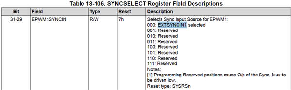
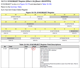
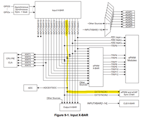
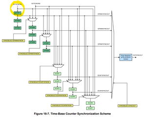
TMS320F28004x 实时微控制器技术参考手册 解释了 ePWM 可以与 EXTSYNCINx 同步、因此外部 SYNC 信号应通过 INPUTXBAR5和/或 INPUTXBAR6直接路由、以提供与 ePWM 和 eCAP 同步链的同步。
为了测试这一概念、我采用了 CCS 参考 示例 epwm_ex3_synchronization.projectspec (位于 C2000Ware_5_00_00_00\driverlib\f28004x\examples\EPWM)并进行了一些修改、使测试非常简单。 因此、我考虑了以下简单场景:
输入 GPIO39 * > INPUTXBAR5 > EXTSYNCIN1 > ePWM1 > GPIO0 (PWM1A)和 GPIO1 (PWM1B)输出
* 向 GPIO39施加外部方波信号(2V 振幅、50%占空比和100Hz)
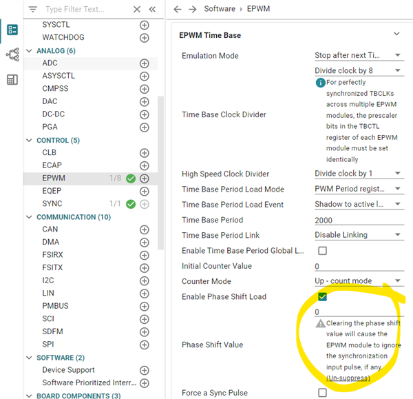
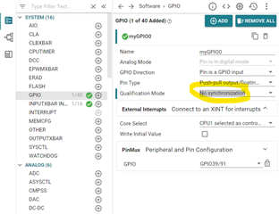
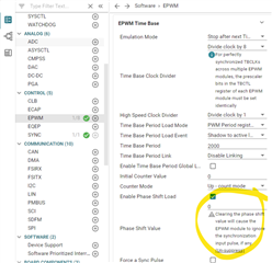
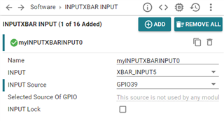
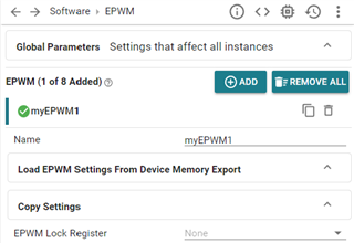
最后的.c 代码在下面分享、在这里、我唯一的贡献是评论与 ePWM2、3和4相关的行、我不打算使用这些行。 下面对.syscfg 代码也进行了小幅修改、其中我将 XBAR 输入5更改为 GPIO39并删除了 myINPUTXBARINPUT1 (XBAR_INPUT6)、下面的屏幕截图 显示了最终配置。 此外、我删除了 myEPWM2、3和4、以下屏幕截图 显示了最终配置。 不会对原始示例应用进一步的更改。
//#############################################################################
//
// FILE:   epwm_ex3_synchronization.c
//
// TITLE:  ePWM Using The Synch Chain and Phase Shift.
//
//! \addtogroup driver_example_list
//! <h1>ePWM Synchronization</h1>
//!
//! This example configures ePWM1, ePWM2, ePWM3 and ePWM4 as follows
//!  - ePWM1 without phase shift as sync source
//!  - ePWM2 with phase shift of 300 TBCLKs
//!  - ePWM3 with phase shift of 600 TBCLKs
//!  - ePWM4 with phase shift of 900 TBCLKs
//!
//! \b External \b Connections \n
//! - GPIO0 EPWM1A
//! - GPIO1 EPWM1B
//! - GPIO2 EPWM2A
//! - GPIO3 EPWM2B
//! - GPIO4 EPWM3A
//! - GPIO5 EPWM3B
//! - GPIO6 EPWM4A
//! - GPIO7 EPWM4B
//!
//! \b Watch \b Variables \n
//! - None.
//
//#############################################################################
//
//
// $Copyright:
// Copyright (C) 2023 Texas Instruments Incorporated - http://www.ti.com/
//
// Redistribution and use in source and binary forms, with or without
// modification, are permitted provided that the following conditions
// are met:
//
//   Redistributions of source code must retain the above copyright
//   notice, this list of conditions and the following disclaimer.
//
//   Redistributions in binary form must reproduce the above copyright
//   notice, this list of conditions and the following disclaimer in the
//   documentation and/or other materials provided with the
//   distribution.
//
//   Neither the name of Texas Instruments Incorporated nor the names of
//   its contributors may be used to endorse or promote products derived
//   from this software without specific prior written permission.
//
// THIS SOFTWARE IS PROVIDED BY THE COPYRIGHT HOLDERS AND CONTRIBUTORS
// "AS IS" AND ANY EXPRESS OR IMPLIED WARRANTIES, INCLUDING, BUT NOT
// LIMITED TO, THE IMPLIED WARRANTIES OF MERCHANTABILITY AND FITNESS FOR
// A PARTICULAR PURPOSE ARE DISCLAIMED. IN NO EVENT SHALL THE COPYRIGHT
// OWNER OR CONTRIBUTORS BE LIABLE FOR ANY DIRECT, INDIRECT, INCIDENTAL,
// SPECIAL, EXEMPLARY, OR CONSEQUENTIAL DAMAGES (INCLUDING, BUT NOT
// LIMITED TO, PROCUREMENT OF SUBSTITUTE GOODS OR SERVICES; LOSS OF USE,
// DATA, OR PROFITS; OR BUSINESS INTERRUPTION) HOWEVER CAUSED AND ON ANY
// THEORY OF LIABILITY, WHETHER IN CONTRACT, STRICT LIABILITY, OR TORT
// (INCLUDING NEGLIGENCE OR OTHERWISE) ARISING IN ANY WAY OUT OF THE USE
// OF THIS SOFTWARE, EVEN IF ADVISED OF THE POSSIBILITY OF SUCH DAMAGE.
// $
//#############################################################################

//
// Included Files
//
#include "driverlib.h"
#include "device.h"
#include "board.h"


__interrupt void epwm1ISR(void);
__interrupt void epwm2ISR(void);
__interrupt void epwm3ISR(void);
__interrupt void epwm4ISR(void);

//
// Main
//
void main(void)
{
    //
    // Initialize device clock and peripherals
    //
    Device_init();

    //
    // Disable pin locks and enable internal pull ups.
    //
    Device_initGPIO();

    //
    // Initialize PIE and clear PIE registers. Disables CPU interrupts.
    //
    Interrupt_initModule();

    //
    // Initialize the PIE vector table with pointers to the shell Interrupt
    // Service Routines (ISR).
    //
    Interrupt_initVectorTable();

    //
    // Assign the interrupt service routines to ePWM interrupts
    //
    Interrupt_register(INT_EPWM1, &epwm1ISR);
    //Interrupt_register(INT_EPWM2, &epwm2ISR);
    //Interrupt_register(INT_EPWM3, &epwm3ISR);
    //Interrupt_register(INT_EPWM4, &epwm4ISR);


    // Disable sync(Freeze clock to PWM as well). GTBCLKSYNC is applicable
    // only for multiple core devices. Uncomment the below statement if
    // applicable.
    //
    // SysCtl_disablePeripheral(SYSCTL_PERIPH_CLK_GTBCLKSYNC);
    SysCtl_disablePeripheral(SYSCTL_PERIPH_CLK_TBCLKSYNC);

    //

    // Configure GPIO0/1 , GPIO2/3 and GPIO4/5 and GPIO6/7 as
    // ePWM1A/1B, ePWM2A/2B, ePWM3A/3B, ePWM4A/4B pins respectively
    // Configure EPWM Modules
    //
    Board_init();

    //
    // Enable sync and clock to PWM
    //
    SysCtl_enablePeripheral(SYSCTL_PERIPH_CLK_TBCLKSYNC);

    //
    // Enable ePWM interrupts
    //
    Interrupt_enable(INT_EPWM1);
    //Interrupt_enable(INT_EPWM2);
    //Interrupt_enable(INT_EPWM3);
    //Interrupt_enable(INT_EPWM4);

    //
    // Enable Global Interrupt (INTM) and realtime interrupt (DBGM)
    //
    EINT;
    ERTM;

    //
    // IDLE loop. Just sit and loop forever (optional):
    //
    for(;;)
    {

    }
}

//
// epwm1ISR - ePWM 1 ISR
//
__interrupt void epwm1ISR(void)
{
    //
    // Clear INT flag for this timer
    //
    EPWM_clearEventTriggerInterruptFlag(myEPWM1_BASE);

    //
    // Acknowledge interrupt group
    //
    Interrupt_clearACKGroup(INTERRUPT_ACK_GROUP3);
}

//
// epwm2ISR - ePWM 2 ISR
//
/*__interrupt void epwm2ISR(void)
{
    //
    // Clear INT flag for this timer
    //
    EPWM_clearEventTriggerInterruptFlag(myEPWM2_BASE);

    //
    // Acknowledge interrupt group
    //
    Interrupt_clearACKGroup(INTERRUPT_ACK_GROUP3);
}

//
// epwm3ISR - ePWM 3 ISR
//
__interrupt void epwm3ISR(void)
{
    //
    // Clear INT flag for this timer
    //
    EPWM_clearEventTriggerInterruptFlag(myEPWM3_BASE);

    //
    // Acknowledge interrupt group
    //
    Interrupt_clearACKGroup(INTERRUPT_ACK_GROUP3);
}

//
// epwm4ISR - ePWM 4 ISR
//
__interrupt void epwm4ISR(void)
{
    //
    // Clear INT flag for this timer
    //
    EPWM_clearEventTriggerInterruptFlag(myEPWM4_BASE);

    //
    // Acknowledge interrupt group
    //
    Interrupt_clearACKGroup(INTERRUPT_ACK_GROUP3);
}*/
/**
 * These arguments were used when this file was generated. They will be automatically applied on subsequent loads
 * via the GUI or CLI. Run CLI with '--help' for additional information on how to override these arguments.
 * @cliArgs --device "F28004x" --package "F28004x_100PZ" --part "F28004x_100PZ" --context "system" --product "C2000WARE@5.00.00.00"
 * @versions {"tool":"1.18.0+3266"}
 */

/**
 * Import the modules used in this configuration.
 */
const epwm             = scripting.addModule("/driverlib/epwm.js", {}, false);
const epwm1            = epwm.addInstance();
const inputxbar        = scripting.addModule("/driverlib/inputxbar.js", {}, false);
const inputxbar1       = inputxbar.addInstance();
const inputxbar_input  = scripting.addModule("/driverlib/inputxbar_input.js");
const inputxbar_input1 = inputxbar_input.addInstance();
const sync             = scripting.addModule("/driverlib/sync.js");

/**
 * Write custom configuration values to the imported modules.
 */
epwm1.$name                                                    = "myEPWM1";
epwm1.epwmTimebase_period                                      = 2000;
epwm1.epwmCounterCompare_cmpA                                  = 1000;
epwm1.epwmCounterCompare_cmpB                                  = 500;
epwm1.epwmTimebase_counterMode                                 = "EPWM_COUNTER_MODE_UP";
epwm1.epwmTimebase_clockDiv                                    = "EPWM_CLOCK_DIVIDER_8";
epwm1.epwmTimebase_hsClockDiv                                  = "EPWM_HSCLOCK_DIVIDER_1";
epwm1.epwmActionQualifier_EPWM_AQ_OUTPUT_A_ON_TIMEBASE_ZERO    = "EPWM_AQ_OUTPUT_HIGH";
epwm1.epwmActionQualifier_EPWM_AQ_OUTPUT_B_ON_TIMEBASE_ZERO    = "EPWM_AQ_OUTPUT_HIGH";
epwm1.epwmActionQualifier_EPWM_AQ_OUTPUT_A_ON_TIMEBASE_UP_CMPA = "EPWM_AQ_OUTPUT_LOW";
epwm1.epwmActionQualifier_EPWM_AQ_OUTPUT_B_ON_TIMEBASE_UP_CMPB = "EPWM_AQ_OUTPUT_LOW";
epwm1.epwmEventTrigger_enableInterrupt                         = true;
epwm1.epwmEventTrigger_interruptEventCount                     = "1";
epwm1.epwmTimebase_syncOutPulseMode                            = "EPWM_SYNC_OUT_PULSE_ON_COUNTER_ZERO";
epwm1.epwm.$assign                                             = "EPWM1";
epwm1.epwm.epwm_aPin.$assign                                   = "GPIO0";
epwm1.epwm.epwm_bPin.$assign                                   = "GPIO1";

inputxbar1.$name = "myINPUTXBAR5";

inputxbar_input1.$name          = "myINPUTXBARINPUT0";
inputxbar_input1.inputxbarInput = "XBAR_INPUT5";
inputxbar_input1.inputxbarGpio  = "GPIO39";
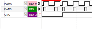
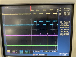
加载代码后、我无法在 GPIO39输入的上升沿看到任何同步。 在帖子的底部 、我附加了一个.ZIP 格式的视频进行测试、您可以 从示波器上看到配置和结果。 黄色显示 GPIO39外部控制信号、蓝色和粉色显示 GPIO0 (PWM1A)和 GPIO1 (PWM1B)
在该示例中、使 PWM 同步可能缺少什么? 为什么 PWM1A 和 PWM1B 不互补?
等待您的答案。
此致、
D·奥维西延科
此处的视频- e2e.ti.com/.../VideoTest.zip