Other Parts Discussed in Thread: SYSCONFIG
请注意,本文内容源自机器翻译,可能存在语法或其它翻译错误,仅供参考。如需获取准确内容,请参阅链接中的英语原文或自行翻译。
器件型号:TMS320F280039C 主题中讨论的其他器件:SysConfig
工具与软件:
Im 使用了 spi_ex3_external_loopback 示例并对其进行了修改、使 Im 在 SPIB 上仅传输16字节的数据、并通过手动控制 SPISTE 引脚。 代码如下:
//
// Included Files
//
#include "driverlib.h"
#include "device.h"
#include "board.h"
#include "f28003x_device.h"


//
//Macros
//
static inline void GPIO_SPI_FLASH_CS_CLEAR(void){
    GpioDataRegs.GPACLEAR.bit.GPIO15 = 1;
}

static inline void GPIO_SPI_FLASH_CS_SET(void)
{
    GpioDataRegs.GPASET.bit.GPIO15 = 1;
}

//
//Prototype
//
uint16_t spi_transmit_byte(uint16_t data_tx);

//
// Main
//
void main(void)
{
    uint16_t i;

    uint16_t TxData_SPIB[] = {0x10, 0x11, 0x12, 0x13, 0x14, 0x15, 0x16, 0x17, 0x18, 0x19, 0x1A, 0x1B, 0x1C, 0x1D, 0x1E, 0x1F};

    //
    // Initialize device clock and peripherals
    //
    Device_init();

    //
    // Disable pin locks and enable internal pullups.
    //
    Device_initGPIO();

    //
    // Initialize PIE and clear PIE registers. Disables CPU interrupts.
    //
    Interrupt_initModule();

    //
    // Initialize the PIE vector table with pointers to the shell Interrupt
    // Service Routines (ISR).
    //
    Interrupt_initVectorTable();

    //
    // Board initialization
    //
    Board_init();

    //
    // Loop forever. Suspend or place breakpoints to observe the buffers.
    //
//    for(i = 0; i < 16; i++)
//    {
//        spi_transmit_byte(TxData_SPIB[i]);
//    }
    spi_transmit_multi_byte(TxData_SPIB, 16);
    //
    // Loop forever
    //
    while(1);
}

uint16_t spi_transmit_byte(uint16_t data_tx)
{
    uint16_t ret_val = 0U;
    /* Shift the data to MSbyte as the 8bit setting discards the LSbyte and transmits only MSbyte
     * Assert the CS low
     * Transmit the data and dummy read
     * Drive the CS high
     */
    data_tx = data_tx << 8U;
    GPIO_SPI_FLASH_CS_CLEAR();
    SPI_writeDataNonBlocking(SPIB_BASE, data_tx);
    SPI_readDataNonBlocking(SPIB_BASE);
    GPIO_SPI_FLASH_CS_SET();
    return ret_val;
}

uint16_t spi_transmit_multi_byte(uint16_t *buffer_tx, uint16_t len)
{
    uint16_t i, data_tx;
    uint16_t ret_val = 0U;
    /* Shift each data to be sent to MSbyte as the 8bit setting discards the LSbyte and transmits only MSbyte
     * Assert the CS low
     * Transmit all the data while dummy reading at the same time
     * Drive the CS high
     */
    GPIO_SPI_FLASH_CS_CLEAR();
    for (i = 0; i < len; i++)
    {
        data_tx = buffer_tx[i] << 8U;
        SPI_writeDataNonBlocking(SPIB_BASE, data_tx);
        SPI_readDataNonBlocking(SPIB_BASE);
    }
    GPIO_SPI_FLASH_CS_SET();
    return ret_val;
}
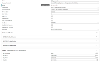
SysConfig 如下所示:

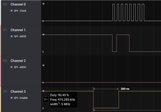
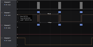
以下是 Im 在逻辑分析仪上观察到的情况:
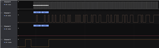
我的问题是 、将 GPIO 用作 SPISTE 引脚会发生什么情况? Im 希望引脚 在整个 for 循环中保持低电平有效、直到传输完成。 我在这里遗漏了什么?