This thread has been locked.
If you have a related question, please click the "Ask a related question" button in the top right corner. The newly created question will be automatically linked to this question.
您好!
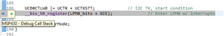
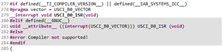
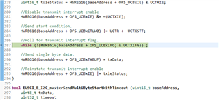
是否有任何用于 MSP430FR5969微控制器与 TMP117温度传感器通信的 I2C 示例代码。 我已经从 SysConfig 工具中下载了 tmp117.c、tmp117.h、mcu.c、mcu.h 和 main.c、但 mcu.c 文件必须针对 MSP430FR5969 I2C 外设进行修改。 任何示例代码都将非常有帮助、谢谢。
您好!
SysConfig 工具不支持 MSP430、具体取决于 SysConfig 页面上列出的器件。 我建议从以下资源开始:
尊敬的 James:
感谢你的答复。
但可以为 MSP430 MCU 修改 mcu.c 文件。 是否可以使用 msp430fr59xx_eusci_i2c_standard_master.c 文件的函数(如上所述)并修改 mcu.c 文件以从传感器获取数据。
e2e.ti.com/.../8508.mcu.ce2e.ti.com/.../6763.mcu.he2e.ti.com/.../8764.main.ce2e.ti.com/.../5758.TMP117.ce2e.ti.com/.../6116.TMP117.h
我将从我提到的资源开始、而不是尝试修改 mcu.c 文件。 您在哪里找到了这些文件?
我从 SynsConfig 工具下载了这些文件、请查看以下链接:
https://dev.ti.com/sysconfig/index.html?product=ascstudio&module=/ti/sensors/tempsensor/TMP116
我已经介绍了您建议的资源、但我最感兴趣的是在我的项目中使用 MSP430FR5969 MCU、而不是 BOOSTXL-SENSORS BoosterPack。
非常感谢
感谢您分享链接。 如果未提供源代码、则很难知道在何处查找提到的文件。 我们的温度传感器团队负责这些 SysConfig 项目、因此我不熟悉它们。 我下载了几个文件、例如"mcu.c"、"main.c"、"tmp117.c"等。我认为您之前对从 I2C 代码示例向这些文件添加代码的评论是合理的。
[引用 userid="489949" URL"~/support/microcontrollers/msp-low-power-microcontrollers-group/msp430/f/msp-low-power-microcontroller-forum/1011454/msp430fr5969-i2c-sample-code-for-the-msp430fr5969-microcontroller-to-communicate-with-the-tmp117-temperature-sensor/3739715 #3739715"]我已经介绍了您建议的资源、但我最感兴趣的是在我的项目中使用 MSP430FR5969 MCU、而不是 BOOSTXL-SENSORS BoosterPack。请记住、BoosterPack 不包含 MCU、是可以插入 LaunchPad 的简单低成本传感器模块。 LaunchPad 将具有 MSP430FR5969等 MCU、BoosterPack 使您 无需跳线或试验板即可快速轻松地将 MCU 连接到其他传感器。 BOOSTXL-SENSORS BoosterPack 应包含一些代码示例、这些代码示例将为您的开发提供有价值的参考、即使 TMP 器件稍有不同。 我找到了较新 的 BOOSTXL-BASSENSORS BoosterPack、它具有 TMP117传感器、但代码示例都是基于 RTOS 的、我看不到任何适用于 MSP430 MCU 的示例。 因此、我将使用另一个 BoosterPack 中的示例作为参考。 例如、查看'i2c_driver.c'文件。 这似乎使用了 DriverLib、这可能会为您节省一些工作。
这是我用于在基于 MSP430F5528的 EVM 上测试 SysConfig 代码的 mcu.c。 我认为它不会与 FR 器件兼容、但您可以将它用作430 driverlib 的起点。
/* * Include Generic Header Files Here */ #include <stdint.h> #include <stdbool.h> #include "mcu.h" #include "driverlib.h" unsigned char transmitLength = 0; unsigned char transmitCount = 0; unsigned char *transmitBuffer; unsigned char receiveCount = 0; unsigned char *receiveBuffer; /********* MCU SPECIFIC I2C CODE STARTS HERE**********/ void mcu_i2cInit(uint8_t busId) { //Stop WDT WDT_A_hold(WDT_A_BASE); //Set the internal pull-up resistors //Ports 4.2 and 4.1 are SCL/SDA, respectively GPIO_setAsInputPinWithPullUpResistor( GPIO_PORT_P4, GPIO_PIN1 + GPIO_PIN2); //Assign I2C pins to USCI_B1 GPIO_setAsPeripheralModuleFunctionOutputPin( GPIO_PORT_P4, GPIO_PIN1 + GPIO_PIN2); //Initialize Master USCI_B_I2C_initMasterParam param = { 0 }; param.selectClockSource = USCI_B_I2C_CLOCKSOURCE_SMCLK; param.i2cClk = UCS_getSMCLK(); param.dataRate = USCI_B_I2C_SET_DATA_RATE_100KBPS; USCI_B_I2C_initMaster(USCI_B1_BASE, ¶m); //Set Transmit mode USCI_B_I2C_setMode(USCI_B1_BASE, USCI_B_I2C_TRANSMIT_MODE); //Enable I2C Module to start operations USCI_B_I2C_enable(USCI_B1_BASE); } int8_t mcu_i2cTransfer(uint8_t busId, uint8_t i2cAddr, uint8_t *dataToWrite, uint8_t writeLength, uint8_t *dataToRead, uint8_t readLength) { USCI_B_I2C_setSlaveAddress(USCI_B1_BASE, i2cAddr); if (writeLength) { transmitBuffer = dataToWrite; transmitLength = writeLength; USCI_B_I2C_setMode(USCI_B1_BASE, USCI_B_I2C_TRANSMIT_MODE); USCI_B_I2C_clearInterrupt(USCI_B1_BASE, USCI_B_I2C_TRANSMIT_INTERRUPT); USCI_B_I2C_enableInterrupt(USCI_B1_BASE, USCI_B_I2C_TRANSMIT_INTERRUPT); //Delay between each transaction // __delay_cycles(50); //Load TX byte counter transmitCount = 1; //Initiate start and send first character USCI_B_I2C_masterSendMultiByteStart(USCI_B1_BASE, transmitBuffer[0]); //Enter low power mode 0 with interrupts enabled. __bis_SR_register(LPM0_bits + GIE); //__no_operation(); } if (readLength) { //Delay until transmission completes // while(USCI_B_I2C_isBusBusy(USCI_B1_BASE)) // { // ; // } USCI_B_I2C_setMode(USCI_B1_BASE, USCI_B_I2C_RECEIVE_MODE); //Enable master Receive interrupt USCI_B_I2C_enableInterrupt(USCI_B1_BASE, USCI_B_I2C_RECEIVE_INTERRUPT); USCI_B_I2C_clearInterrupt(USCI_B1_BASE, USCI_B_I2C_RECEIVE_INTERRUPT); receiveCount = readLength; receiveBuffer = dataToRead; if (receiveCount == 1) { // USCI_B_I2C_disableInterrupt(USCI_B1_BASE,USCI_B_I2C_RECEIVE_INTERRUPT); // USCI_B_I2C_clearInterrupt(USCI_B1_BASE,USCI_B_I2C_RECEIVE_INTERRUPT); // USCI_B_I2C_masterReceiveSingleStart(USCI_B1_BASE); // dataToRead[0] = USCI_B_I2C_masterReceiveMultiByteNext(USCI_B1_BASE); //Set USCI in Receive mode HWREG8(USCI_B1_BASE + OFS_UCBxCTL1) &= ~UCTR; //Send start condition. HWREG8(USCI_B1_BASE + OFS_UCBxCTL1) |= UCTXSTT; //Poll for Start bit to complete while (HWREG8(USCI_B1_BASE + OFS_UCBxCTL1) & UCTXSTT) { ; } //Send stop condition. HWREG8(USCI_B1_BASE + OFS_UCBxCTL1) |= UCTXSTP; __bis_SR_register(LPM0_bits + GIE); } else { USCI_B_I2C_masterReceiveMultiByteStart(USCI_B1_BASE); //Enter low power mode 0 with interrupts enabled. __bis_SR_register(LPM0_bits + GIE); } } return (0); } /********* MCU SPECIFIC I2C CODE ENDS HERE**********/ /********* MCU SPECIFIC DELAY CODE ENDS HERE************/ void mcu_msWait(unsigned long msWait) { __delay_cycles(50); } /********* MCU SPECIFIC DELAY CODE ENDS HERE************/ #if defined(__TI_COMPILER_VERSION__) || defined(__IAR_SYSTEMS_ICC__) #pragma vector = USCI_B1_VECTOR; __interrupt #elif defined(__GNUC__) __attribute__((interrupt(USCI_B1_VECTOR))) #endif void USCI_B1_ISR(void) { switch (__even_in_range(UCB1IV, 12)) { case USCI_I2C_UCTXIFG: { //Check TX byte counter if (transmitCount < transmitLength) { //Initiate send of character from Master to Slave USCI_B_I2C_masterSendMultiByteNext(USCI_B1_BASE, transmitBuffer[transmitCount]); //Increment TX byte counter transmitCount++; } else { //Initiate stop only USCI_B_I2C_masterSendMultiByteStop(USCI_B1_BASE); //Clear master interrupt status USCI_B_I2C_clearInterrupt(USCI_B1_BASE, USCI_B_I2C_TRANSMIT_INTERRUPT); //Exit LPM0 on interrupt return __bic_SR_register_on_exit(LPM0_bits); } break; } case USCI_I2C_UCRXIFG: { //Decrement RX byte counter receiveCount--; if (receiveCount) { if (receiveCount == 1) { //Initiate end of reception -> Receive byte with NAK *receiveBuffer++ = USCI_B_I2C_masterReceiveMultiByteNext(USCI_B1_BASE); USCI_B_I2C_clearInterrupt(USCI_B1_BASE, USCI_B_I2C_RECEIVE_INTERRUPT); __bic_SR_register_on_exit(LPM0_bits); } else { //Keep receiving one byte at a time *receiveBuffer++ = USCI_B_I2C_masterReceiveMultiByteNext(USCI_B1_BASE); } } else { //Receive last byte *receiveBuffer = USCI_B_I2C_masterReceiveMultiByteNext(USCI_B1_BASE); USCI_B_I2C_disableInterrupt(USCI_B1_BASE, USCI_B_I2C_RECEIVE_INTERRUPT); USCI_B_I2C_clearInterrupt(USCI_B1_BASE, USCI_B_I2C_RECEIVE_INTERRUPT); __bic_SR_register_on_exit(LPM0_bits); } break; } } }
感谢 James 和 Ren 的帮助。
我 尝试 通过示波器分析 SCL 和 SDA 总线的波形。 当我运行 msp430fr59xx_eusci_i2c_standard_master.c 时、我会得到一个非常奇怪的波形 我已附加下图。 我将 LaunchPad 与 MSP430FR5969配合使用并连接到 TMP117 (从器件地址0*048)。 我使用了10K 上拉电阻器。
当我运行代码时、编译、加载和初始化成功进行、但在不同的位置停止并给出消息、例如 MSP430-Debug Call Stack。 如何解决此 问题。
在以下函数中也会出现相同的调试问题:
堆栈大小:
但是、如果我从资源浏览器中运行 eusci_b_i2c_ex2_masterRxSingle.c、我得到了以下波形、而没有任何调试问题、这些问题看起来是相同的。
非常感谢
我建议您浏览 I2C Academy and Solutions to Common eUSCI and USCI Serial Communication Issues on MSP430 MCU (我之前链接过这些问题)。
[引用 userid="489949" URL"~/support/microcontrollers/msp-low-power-microcontrollers-group/msp430/f/msp-low-power-microcontroller-forum/1011454/msp430fr5969-i2c-sample-code-for-the-msp430fr5969-microcontroller-to-communicate-with-the-tmp117-temperature-sensor/3740991 #3740991"]我使用了10K 上拉电阻器[/quot]这有点高。 我建议将其降低至4.7K 或更低、尤其是在通信速度超过100kHz 且使用为 I2C 线路添加电容的跳线时。
[引用 userid="489949" URL"~/support/microcontrollers/msp-low-power-microcontrollers-group/msp430/f/msp-low-power-microcontroller-forum/1011454/msp430fr5969-i2c-sample-code-for-the-msp430fr5969-microcontroller-to-communicate-with-the-tmp117-temperature-sensor/3740991 #3740991"]当我运行 msp430fr59xx_eusci_i2c_standard_master.c.时、我会得到一个非常奇怪的波形。感谢您介绍您使用的示例。 此示例是寄存器级代码、I2C 时钟速度为100kHz。
[引用 userid="489949" URL"~/support/microcontrollers/msp-low-power-microcontrollers-group/msp430/f/msp-low-power-microcontroller-forum/1011454/msp430fr5969-i2c-sample-code-for-the-msp430fr5969-microcontroller-to-communicate-with-the-tmp117-temperature-sensor/3740991 #3740991"]当我运行代码时、编译、加载和初始化会成功执行、但会在不同位置停止并显示消息、例如 MSP430-Debug Call Stack。 如何解决此 问题。 [/报价]请记住、器件会在特定时间进入低功耗模式。 这并不是一个真正的问题。
[引用 userid="489949" URL"~/support/microcontrollers/msp-low-power-microcontrollers-group/msp430/f/msp-low-power-microcontroller-forum/1011454/msp430fr5969-i2c-sample-code-for-the-msp430fr5969-microcontroller-to-communicate-with-the-tmp117-temperature-sensor/3740991 #3740991"]但是、如果我从资源浏览器运行 eusci_b_i2c_ex2_masterRxSingle.c、我得到了以下波形、而没有任何调试问题、这些问题看起来完全相同。 [/报价]此示例是库级代码、I2C 时钟速度为400kHz。
尊敬的 James:
感谢你的答复。 我已经按照 MSP430 I2C Academy 文章中所述的 I2C 主设备示例"msp430fr243x_eusci_i2c_standard_master.c"进行了操作、并相应地修改了 TMP117的 msp430fr59xx_eusci_i2c_standard_master.c。 它们还将 SMCLK 设置为100kHz、但得到正确的波形。 我不知道我为什么会得到错误的波形。 要获得正确的波形、我需要做什么?
非常感谢
尊敬的 James:
我将 delay 函数的值从 1600000更改为2000毫秒、现在得到以下波形:
以下是修改后的代码:
//****************************************************************************** // MSP430FR59xx Demo - eUSCI_B0, I2C Master multiple byte TX/RX // // Description: I2C master communicates to I2C slave sending and receiving // 3 different messages of different length. I2C master will enter LPM0 mode // while waiting for the messages to be sent/receiving using I2C interrupt. // ACLK = NA, MCLK = SMCLK = DCO 16MHz. // // /|\ /|\ // MSP430FR5969 4.7k | // ----------------- | 4.7k // /|\ | P1.7|---+---|-- I2C Clock (UCB0SCL) // | | | | // ---|RST P1.6|-------+-- I2C Data (UCB0SDA) // | | // | | // | | // | | // | | // | | // // Nima Eskandari // Texas Instruments Inc. // April 2017 // Built with CCS V7.0 //****************************************************************************** #include <msp430.h> #include <stdint.h> #include <stdbool.h> //****************************************************************************** // Example Commands ************************************************************ //****************************************************************************** #define SLAVE_ADDR 0x48 #define CONVERSION_READY 0x10 #define TMP117_TEMP_REG 0x00 #define TMP117_CONFIG_REG 0x01 /* CMD_TYPE_X_SLAVE are example commands the master sends to the slave. * The slave will send example SlaveTypeX buffers in response. * * CMD_TYPE_X_MASTER are example commands the master sends to the slave. * The slave will initialize itself to receive MasterTypeX example buffers. * */ #define CMD_TYPE_0_SLAVE 0 #define CMD_TYPE_1_SLAVE 1 #define CMD_TYPE_2_SLAVE 2 #define CMD_TYPE_0_MASTER 3 #define CMD_TYPE_1_MASTER 4 #define CMD_TYPE_2_MASTER 5 #define TYPE_0_LENGTH 1 #define TYPE_1_LENGTH 2 #define TYPE_2_LENGTH 6 #define MAX_BUFFER_SIZE 20 /* MasterTypeX are example buffers initialized in the master, they will be * sent by the master to the slave. * SlaveTypeX are example buffers initialized in the slave, they will be * sent by the slave to the master. * */ uint8_t MasterType2 [TYPE_2_LENGTH] = {'F', '4', '1', '9', '2', 'B'}; //uint8_t MasterType1 [TYPE_1_LENGTH] = { 8, 9}; uint8_t MasterType1 [TYPE_1_LENGTH] = {0x02, 0x20}; uint8_t MasterType0 [TYPE_0_LENGTH] = {11}; uint8_t SlaveType2 [TYPE_2_LENGTH] = {0}; uint8_t SlaveType1 [TYPE_1_LENGTH] = {0}; uint8_t SlaveType0 [TYPE_0_LENGTH] = {0}; //****************************************************************************** // General I2C State Machine *************************************************** //****************************************************************************** typedef enum I2C_ModeEnum{ IDLE_MODE, NACK_MODE, TX_REG_ADDRESS_MODE, RX_REG_ADDRESS_MODE, TX_DATA_MODE, RX_DATA_MODE, SWITCH_TO_RX_MODE, SWITHC_TO_TX_MODE, TIMEOUT_MODE } I2C_Mode; /* Used to track the state of the software state machine*/ I2C_Mode MasterMode = IDLE_MODE; /* The Register Address/Command to use*/ uint8_t TransmitRegAddr = 0; /* ReceiveBuffer: Buffer used to receive data in the ISR * RXByteCtr: Number of bytes left to receive * ReceiveIndex: The index of the next byte to be received in ReceiveBuffer * TransmitBuffer: Buffer used to transmit data in the ISR * TXByteCtr: Number of bytes left to transfer * TransmitIndex: The index of the next byte to be transmitted in TransmitBuffer * */ uint8_t ReceiveBuffer[MAX_BUFFER_SIZE] = {0}; uint8_t RXByteCtr = 0; uint8_t ReceiveIndex = 0; uint8_t TransmitBuffer[MAX_BUFFER_SIZE] = {0}; uint8_t TXByteCtr = 0; uint8_t TransmitIndex = 0; /* I2C Write and Read Functions */ /* For slave device with dev_addr, writes the data specified in *reg_data * * dev_addr: The slave device address. * Example: SLAVE_ADDR * reg_addr: The register or command to send to the slave. * Example: CMD_TYPE_0_MASTER * *reg_data: The buffer to write * Example: MasterType0 * count: The length of *reg_data * Example: TYPE_0_LENGTH * */ I2C_Mode I2C_Master_WriteReg(uint8_t dev_addr, uint8_t reg_addr, uint8_t *reg_data, uint8_t count); /* For slave device with dev_addr, read the data specified in slaves reg_addr. * The received data is available in ReceiveBuffer * * dev_addr: The slave device address. * Example: SLAVE_ADDR * reg_addr: The register or command to send to the slave. * Example: CMD_TYPE_0_SLAVE * count: The length of data to read * Example: TYPE_0_LENGTH * */ I2C_Mode I2C_Master_ReadReg(uint8_t dev_addr, uint8_t reg_addr, uint8_t count); void CopyArray(uint8_t *source, uint8_t *dest, uint8_t count); I2C_Mode I2C_Master_ReadReg(uint8_t dev_addr, uint8_t reg_addr, uint8_t count) { /* Initialize state machine */ MasterMode = TX_REG_ADDRESS_MODE; TransmitRegAddr = reg_addr; RXByteCtr = count; TXByteCtr = 0; ReceiveIndex = 0; TransmitIndex = 0; /* Initialize slave address and interrupts */ UCB0I2CSA = dev_addr; UCB0IFG &= ~(UCTXIFG + UCRXIFG); // Clear any pending interrupts UCB0IE &= ~UCRXIE; // Disable RX interrupt UCB0IE |= UCTXIE; // Enable TX interrupt UCB0CTLW0 |= UCTR + UCTXSTT; // I2C TX, start condition __bis_SR_register(LPM0_bits + GIE); // Enter LPM0 w/ interrupts return MasterMode; } I2C_Mode I2C_Master_WriteReg(uint8_t dev_addr, uint8_t reg_addr, uint8_t *reg_data, uint8_t count) { /* Initialize state machine */ MasterMode = TX_REG_ADDRESS_MODE; TransmitRegAddr = reg_addr; //Copy register data to TransmitBuffer CopyArray(reg_data, TransmitBuffer, count); TXByteCtr = count; RXByteCtr = 0; ReceiveIndex = 0; TransmitIndex = 0; /* Initialize slave address and interrupts */ UCB0I2CSA = dev_addr; UCB0IFG &= ~(UCTXIFG + UCRXIFG); // Clear any pending interrupts UCB0IE &= ~UCRXIE; // Disable RX interrupt UCB0IE |= UCTXIE; // Enable TX interrupt UCB0CTLW0 |= UCTR + UCTXSTT; // I2C TX, start condition __bis_SR_register(LPM0_bits + GIE); // Enter LPM0 w/ interrupts return MasterMode; } void CopyArray(uint8_t *source, uint8_t *dest, uint8_t count) { uint8_t copyIndex = 0; for (copyIndex = 0; copyIndex < count; copyIndex++) { dest[copyIndex] = source[copyIndex]; } } //****************************************************************************** // Device Initialization ******************************************************* //****************************************************************************** void initGPIO() { // Configure GPIO P1OUT &= ~BIT0; // Clear P1.0 output latch P1DIR |= BIT0; // For LED P1SEL1 |= BIT6 | BIT7; // I2C pins // Disable the GPIO power-on default high-impedance mode to activate // previously configured port settings PM5CTL0 &= ~LOCKLPM5; } void initClockTo16MHz() { // Configure one FRAM waitstate as required by the device datasheet for MCLK // operation beyond 8MHz _before_ configuring the clock system. FRCTL0 = FRCTLPW | NWAITS_1; // Clock System Setup CSCTL0_H = CSKEY >> 8; // Unlock CS registers CSCTL1 = DCORSEL | DCOFSEL_4; // Set DCO to 16MHz CSCTL2 = SELA__VLOCLK | SELS__DCOCLK | SELM__DCOCLK; CSCTL3 = DIVA__1 | DIVS__1 | DIVM__1; // Set all dividers CSCTL0_H = 0; // Lock CS registerss } void initI2C() { UCB0CTLW0 = UCSWRST; // Enable SW reset UCB0CTLW0 |= UCMODE_3 | UCMST | UCSSEL__SMCLK | UCSYNC; // I2C master mode, SMCLK UCB0BRW = 160; // fSCL = SMCLK/160 = ~100kHz UCB0I2CSA = SLAVE_ADDR; // Slave Address UCB0CTLW0 &= ~UCSWRST; // Clear SW reset, resume operation UCB0IE |= UCNACKIE; } //****************************************************************************** // Main ************************************************************************ // Send and receive three messages containing the example commands ************* //****************************************************************************** int main(void) { WDTCTL = WDTPW | WDTHOLD; // Stop watchdog timer initClockTo16MHz(); initGPIO(); initI2C(); //I2C_Master_WriteReg(SLAVE_ADDR, CMD_TYPE_0_MASTER, MasterType0, TYPE_0_LENGTH); I2C_Master_WriteReg(SLAVE_ADDR, 0x01, MasterType1, TYPE_1_LENGTH); while(1) { _delay_cycles(2000); I2C_Master_ReadReg(SLAVE_ADDR, 0x00, TYPE_1_LENGTH); CopyArray(ReceiveBuffer, SlaveType1, TYPE_1_LENGTH); if(ReceiveBuffer[1] & CONVERSION_READY) { I2C_Master_ReadReg(SLAVE_ADDR, 0x00, TYPE_1_LENGTH); CopyArray(ReceiveBuffer, SlaveType1, TYPE_1_LENGTH); _no_operation(); } } //I2C_Master_WriteReg(SLAVE_ADDR, CMD_TYPE_2_MASTER, MasterType2, TYPE_2_LENGTH); ///I2C_Master_ReadReg(SLAVE_ADDR, CMD_TYPE_0_SLAVE, TYPE_0_LENGTH); //CopyArray(ReceiveBuffer, SlaveType0, TYPE_0_LENGTH); //I2C_Master_ReadReg(SLAVE_ADDR, 0x00, TYPE_1_LENGTH); //CopyArray(ReceiveBuffer, SlaveType1, TYPE_1_LENGTH); //I2C_Master_ReadReg(SLAVE_ADDR, CMD_TYPE_2_SLAVE, TYPE_2_LENGTH); // CopyArray(ReceiveBuffer, SlaveType2, TYPE_2_LENGTH); // __bis_SR_register(LPM0_bits + GIE); //return 0; } //****************************************************************************** // I2C Interrupt *************************************************************** //****************************************************************************** #if defined(__TI_COMPILER_VERSION__) || defined(__IAR_SYSTEMS_ICC__) #pragma vector = USCI_B0_VECTOR __interrupt void USCI_B0_ISR(void) #elif defined(__GNUC__) void __attribute__ ((interrupt(USCI_B0_VECTOR))) USCI_B0_ISR (void) #else #error Compiler not supported! #endif { //Must read from UCB0RXBUF uint8_t rx_val = 0; switch(__even_in_range(UCB0IV, USCI_I2C_UCBIT9IFG)) { case USCI_NONE: break; // Vector 0: No interrupts case USCI_I2C_UCALIFG: break; // Vector 2: ALIFG case USCI_I2C_UCNACKIFG: // Vector 4: NACKIFG break; case USCI_I2C_UCSTTIFG: break; // Vector 6: STTIFG case USCI_I2C_UCSTPIFG: break; // Vector 8: STPIFG case USCI_I2C_UCRXIFG3: break; // Vector 10: RXIFG3 case USCI_I2C_UCTXIFG3: break; // Vector 12: TXIFG3 case USCI_I2C_UCRXIFG2: break; // Vector 14: RXIFG2 case USCI_I2C_UCTXIFG2: break; // Vector 16: TXIFG2 case USCI_I2C_UCRXIFG1: break; // Vector 18: RXIFG1 case USCI_I2C_UCTXIFG1: break; // Vector 20: TXIFG1 case USCI_I2C_UCRXIFG0: // Vector 22: RXIFG0 rx_val = UCB0RXBUF; if (RXByteCtr) { ReceiveBuffer[ReceiveIndex++] = rx_val; RXByteCtr--; } if (RXByteCtr == 1) { UCB0CTLW0 |= UCTXSTP; } else if (RXByteCtr == 0) { UCB0IE &= ~UCRXIE; MasterMode = IDLE_MODE; __bic_SR_register_on_exit(CPUOFF); // Exit LPM0 } break; case USCI_I2C_UCTXIFG0: // Vector 24: TXIFG0 switch (MasterMode) { case TX_REG_ADDRESS_MODE: UCB0TXBUF = TransmitRegAddr; if (RXByteCtr) MasterMode = SWITCH_TO_RX_MODE; // Need to start receiving now else MasterMode = TX_DATA_MODE; // Continue to transmision with the data in Transmit Buffer break; case SWITCH_TO_RX_MODE: UCB0IE |= UCRXIE; // Enable RX interrupt UCB0IE &= ~UCTXIE; // Disable TX interrupt UCB0CTLW0 &= ~UCTR; // Switch to receiver MasterMode = RX_DATA_MODE; // State state is to receive data UCB0CTLW0 |= UCTXSTT; // Send repeated start if (RXByteCtr == 1) { //Must send stop since this is the N-1 byte while((UCB0CTLW0 & UCTXSTT)); UCB0CTLW0 |= UCTXSTP; // Send stop condition } break; case TX_DATA_MODE: if (TXByteCtr) { UCB0TXBUF = TransmitBuffer[TransmitIndex++]; TXByteCtr--; } else { //Done with transmission UCB0CTLW0 |= UCTXSTP; // Send stop condition MasterMode = IDLE_MODE; UCB0IE &= ~UCTXIE; // disable TX interrupt __bic_SR_register_on_exit(CPUOFF); // Exit LPM0 } break; default: __no_operation(); break; } break; default: break; } }
任您好、
我已尝试修改您的 MSP430FR5969 MCU 代码。 但是、我无法从传感器获取任何数据。 我正在尝试读取 TM117温度传感器、该传感器具有以下规格。
TMP117传感器地址= 0x48 温度寄存器= 0x00
配置寄存器= 0x01 TMP117分辨率0.0078125f
我不知道如何正确修改代码中的读取函数以从传感器获取数据。 请根据 TM117传感器规格帮助修改写入和读取函数。
这是修改后的代码。
#include <msp430.h> #include "driverlib.h" #include <stdint.h> #include <stdbool.h> #include "mcu.h" unsigned char transmitLength = 0; unsigned char transmitCount = 0; unsigned char *transmitBuffer; unsigned char receiveCount = 0; unsigned char *receiveBuffer; #define SLAVE_ADDR 0x48 // sensor address #define TMP117_TEMP_REG 0x00 //temperature register #define TMP117_CONFIG_REG 0x01 //Configuration registry #define TMP117_RESOLUTION 0.0078125f // sensor resolution void mcu_i2cInit(uint8_t busId) { //Stop WDT WDT_A_hold(WDT_A_BASE); //Set the internal pull-up resistors //Ports 4.2 and 4.1 are SCL/SDA, respectively //GPIO_setAsInputPinWithPullUpResistor(GPIO_PORT_P4, //GPIO_PIN1 + GPIO_PIN2); //Assign I2C pins to USCI_B1 //GPIO_setAsPeripheralModuleFunctionOutputPin( //GPIO_PORT_P4, //GPIO_PIN1 + GPIO_PIN2); GPIO_setAsPeripheralModuleFunctionInputPin( GPIO_PORT_P1, GPIO_PIN6 + GPIO_PIN7, GPIO_SECONDARY_MODULE_FUNCTION ); PMM_unlockLPM5(); //Initialize Master EUSCI_B_I2C_initMasterParam param = {0}; param.selectClockSource = EUSCI_B_I2C_CLOCKSOURCE_SMCLK; param.i2cClk = CS_getSMCLK(); param.dataRate = EUSCI_B_I2C_SET_DATA_RATE_100KBPS; EUSCI_B_I2C_initMaster(EUSCI_B0_BASE, ¶m); //Set Transmit mode EUSCI_B_I2C_setMode(EUSCI_B0_BASE, EUSCI_B_I2C_TRANSMIT_MODE); //Enable I2C Module to start operations EUSCI_B_I2C_enable(EUSCI_B0_BASE); } int8_t mcu_i2cTransfer(uint8_t busId, uint8_t i2cAddr, uint8_t *dataToWrite, uint8_t writeLength, uint8_t *dataToRead, uint8_t readLength) { EUSCI_B_I2C_setSlaveAddress(EUSCI_B0_BASE, i2cAddr); if (writeLength) { transmitBuffer = dataToWrite; transmitLength = writeLength; EUSCI_B_I2C_setMode(EUSCI_B0_BASE, EUSCI_B_I2C_TRANSMIT_MODE); EUSCI_B_I2C_clearInterrupt(EUSCI_B0_BASE, EUSCI_B_I2C_TRANSMIT_INTERRUPT0); EUSCI_B_I2C_enableInterrupt(EUSCI_B0_BASE, EUSCI_B_I2C_TRANSMIT_INTERRUPT0); //Delay between each transaction __delay_cycles(50); //Load TX byte counter transmitCount = 1; //Initiate start and send first character EUSCI_B_I2C_masterSendMultiByteStart(EUSCI_B0_BASE, transmitBuffer[0]); //Enter low power mode 0 with interrupts enabled. __bis_SR_register(LPM0_bits + GIE); //__no_operation(); } if (readLength) { //Delay until transmission completes // while(USCI_B_I2C_isBusBusy(EUSCI_B0_BASE)) // { // ; // } EUSCI_B_I2C_setMode(EUSCI_B0_BASE, EUSCI_B_I2C_RECEIVE_MODE); //Enable master Receive interrupt EUSCI_B_I2C_enableInterrupt(EUSCI_B0_BASE, EUSCI_B_I2C_RECEIVE_INTERRUPT0); EUSCI_B_I2C_clearInterrupt(EUSCI_B0_BASE, EUSCI_B_I2C_RECEIVE_INTERRUPT0); receiveCount = readLength; receiveBuffer = dataToRead; if (receiveCount == 1) { EUSCI_B_I2C_disableInterrupt(EUSCI_B0_BASE, EUSCI_B_I2C_RECEIVE_INTERRUPT0); EUSCI_B_I2C_clearInterrupt(EUSCI_B0_BASE, EUSCI_B_I2C_RECEIVE_INTERRUPT0); EUSCI_B_I2C_masterReceiveStart(EUSCI_B0_BASE); //dataToRead[0] = EUSCI_B_I2C_masterReceiveMultiByteNext(EUSCI_B0_BASE); //Set USCI in Receive mode HWREG16(EUSCI_B0_BASE + OFS_UCBxCTLW0) &= ~UCTR; //Send start condition. HWREG16(EUSCI_B0_BASE + OFS_UCBxCTLW0) |= UCTXSTT; //Poll for Start bit to complete while (HWREG16(EUSCI_B0_BASE + OFS_UCBxCTLW0) & UCTXSTT) { ; } //Send stop condition. HWREG16(EUSCI_B0_BASE + OFS_UCBxCTLW0) |= UCTXSTP; __bis_SR_register(LPM0_bits + GIE); } else { EUSCI_B_I2C_masterReceiveStart(EUSCI_B0_BASE); //Enter low power mode 0 with interrupts enabled. __bis_SR_register(LPM0_bits + GIE); } } return (0); } /********* MCU SPECIFIC I2C CODE ENDS HERE**********/ /********* MCU SPECIFIC DELAY CODE ENDS HERE************/ void mcu_msWait(unsigned long msWait) { __delay_cycles(50); } /********* MCU SPECIFIC DELAY CODE ENDS HERE************/ #if defined(__TI_COMPILER_VERSION__) || defined(__IAR_SYSTEMS_ICC__) #pragma vector = USCI_B0_VECTOR; __interrupt #elif defined(__GNUC__) __attribute__((interrupt(USCI_B0_VECTOR))) #endif void USCI_B1_ISR(void) { switch (__even_in_range(UCB0IV, 12)) { case USCI_I2C_UCTXIFG0: { //Check TX byte counter if (transmitCount < transmitLength) { //Initiate send of character from Master to Slave EUSCI_B_I2C_masterSendMultiByteNext(EUSCI_B0_BASE, transmitBuffer[transmitCount]); //Increment TX byte counter transmitCount++; } else { //Initiate stop only EUSCI_B_I2C_masterSendMultiByteStop(EUSCI_B0_BASE); //Clear master interrupt status EUSCI_B_I2C_clearInterrupt(EUSCI_B0_BASE, EUSCI_B_I2C_TRANSMIT_INTERRUPT0); //Exit LPM0 on interrupt return __bic_SR_register_on_exit(LPM0_bits); } break; } case USCI_I2C_UCRXIFG0: { //Decrement RX byte counter receiveCount--; if (receiveCount) { if (receiveCount == 1) { //Initiate end of reception -> Receive byte with NAK *receiveBuffer++ = EUSCI_B_I2C_masterReceiveMultiByteNext(EUSCI_B0_BASE); EUSCI_B_I2C_clearInterrupt(EUSCI_B0_BASE, EUSCI_B_I2C_RECEIVE_INTERRUPT0); __bic_SR_register_on_exit(LPM0_bits); } else { //Keep receiving one byte at a time *receiveBuffer++ = EUSCI_B_I2C_masterReceiveMultiByteNext(EUSCI_B0_BASE); } } else { //Receive last byte *receiveBuffer = EUSCI_B_I2C_masterReceiveMultiByteNext(EUSCI_B0_BASE); EUSCI_B_I2C_disableInterrupt(EUSCI_B0_BASE, EUSCI_B_I2C_RECEIVE_INTERRUPT0); EUSCI_B_I2C_clearInterrupt(EUSCI_B0_BASE, EUSCI_B_I2C_RECEIVE_INTERRUPT0); __bic_SR_register_on_exit(LPM0_bits); } break; } } }
非常感谢。
您是否参考了 TMP117数据表中提供的写入和读取时序图? 数据表中的第7.5.3.1.3节"写入和读取操作"也应该有所帮助。 您的命令与这些命令相比如何? TMP117是发送 ACK 还是 NACK? 通信在哪里停止正常工作?
尊敬的 James:
感谢你的答复。
我尝试使用 I2C 函数来修改 mcu.c 文件、以便可以使用 TM117.h 库读取温度值。 建议的代码 REN 与 msp430fr59xx_eusci_i2c_standard_master.c 稍有不同
[引用 userid="216616" URL"~/support/microcontrollers/msp-low-power-microcontrollers-group/msp430/f/msp-low-power-microcontroller-forum/1011454/msp430fr5969-i2c-sample-code-for-the-msp430fr5969-microcontroller-to-communicate-with-the-tmp117-temperature-sensor/3747319 #3747319"]您是否引用了 TMP117数据表中提供的写入和读取时序图?没错。 我不确定如何正确修改 REN 建议的 mcu.c 文件中的写入和读取命令。 我在 msp430fr59xx_eusci_i2c_standard_master.c 中使用了以下读取和写入函数来读取 TM117温度寄存器、该寄存器工作正常。
int main(void) { WDTCTL = WDTPW | WDTHOLD; // Stop watchdog timer initClockTo16MHz(); initGPIO(); initI2C(); //I2C_Master_WriteReg(SLAVE_ADDR, CMD_TYPE_0_MASTER, MasterType0, TYPE_0_LENGTH); I2C_Master_WriteReg(SLAVE_ADDR, 0x01, MasterType1, TYPE_1_LENGTH); while(1) { _delay_cycles(500000); // _delay_cycles(1600); I2C_Master_ReadReg(SLAVE_ADDR, 0x00, TYPE_1_LENGTH); CopyArray(ReceiveBuffer, SlaveType1, TYPE_1_LENGTH); if(ReceiveBuffer[1] & CONVERSION_READY) { I2C_Master_ReadReg(SLAVE_ADDR, 0x00, TYPE_1_LENGTH); CopyArray(ReceiveBuffer, SlaveType1, TYPE_1_LENGTH); _no_operation(); } }
这就是我得到的结果:
当我暂停调试时、代码卡在 EUSCI_B_I2C 文件中、如下所示、因此它永远不会完成执行。 只需明确四个文件:(1) main.c、(ii) mcu.c、(iii) mcu.h (iv) tmp117.c 和(v) tmp117.h
非常感谢
您可能需要重新组织一些写入和读取函数来实现这一点。 例如、TMP117传感器的"读取"命令可能仍需要在读取数据之前进行写入。
[引用 userid="489949" URL"~/support/microcontrollers/msp-low-power-microcontrollers-group/msp430/f/msp-low-power-microcontroller-forum/1011454/msp430fr5969-i2c-sample-code-for-the-msp430fr5969-microcontroller-to-communicate-with-the-tmp117-temperature-sensor/3748651 #3748651"]当我暂停调试时、代码卡在 EUSCI_B_I2C 文件中、如下所示、因此从未完成执行。这可能是因为您使用的是最初用于 F5xx 器件的代码、而您使用的是 FR59xx 器件。 您可能需要通读 《 从 MSP430F5xx 和 MSP430F6xx 系列迁移到 MSP430FR58xx/FR59xx/68xx/69xx 系列 》应用手册的"增强型通用串行通信接口"部分。 此外、我还将查看 FR59xx 用户指南、详细了解在禁用中断并发送启动条件后为什么 TXIFG 未被置位。
尊敬的 James:
但愿你一切顺利。 我正在尝试使用 UART 接口在外部终端(我使用了 PuTTY)上打印字符串。 我已经修改 了 msp430fr59xx_euscia0_UART_03.c 来传输整数、如56。 我希望可以使用 UART 接口在终端上打印温度值。
这是 msp430fr59xx_euscia0_UART_03.c 的修改代码:
/* --COPYRIGHT--,BSD_EX * Copyright (c) 2012, Texas Instruments Incorporated * All rights reserved. * * Redistribution and use in source and binary forms, with or without * modification, are permitted provided that the following conditions * are met: * * * Redistributions of source code must retain the above copyright * notice, this list of conditions and the following disclaimer. * * * Redistributions in binary form must reproduce the above copyright * notice, this list of conditions and the following disclaimer in the * documentation and/or other materials provided with the distribution. * * * Neither the name of Texas Instruments Incorporated nor the names of * its contributors may be used to endorse or promote products derived * from this software without specific prior written permission. * * THIS SOFTWARE IS PROVIDED BY THE COPYRIGHT HOLDERS AND CONTRIBUTORS "AS IS" * AND ANY EXPRESS OR IMPLIED WARRANTIES, INCLUDING, BUT NOT LIMITED TO, * THE IMPLIED WARRANTIES OF MERCHANTABILITY AND FITNESS FOR A PARTICULAR * PURPOSE ARE DISCLAIMED. IN NO EVENT SHALL THE COPYRIGHT OWNER OR * CONTRIBUTORS BE LIABLE FOR ANY DIRECT, INDIRECT, INCIDENTAL, SPECIAL, * EXEMPLARY, OR CONSEQUENTIAL DAMAGES (INCLUDING, BUT NOT LIMITED TO, * PROCUREMENT OF SUBSTITUTE GOODS OR SERVICES; LOSS OF USE, DATA, OR PROFITS; * OR BUSINESS INTERRUPTION) HOWEVER CAUSED AND ON ANY THEORY OF LIABILITY, * WHETHER IN CONTRACT, STRICT LIABILITY, OR TORT (INCLUDING NEGLIGENCE OR * OTHERWISE) ARISING IN ANY WAY OUT OF THE USE OF THIS SOFTWARE, * EVEN IF ADVISED OF THE POSSIBILITY OF SUCH DAMAGE. * ******************************************************************************* * * MSP430 CODE EXAMPLE DISCLAIMER * * MSP430 code examples are self-contained low-level programs that typically * demonstrate a single peripheral function or device feature in a highly * concise manner. For this the code may rely on the device's power-on default * register values and settings such as the clock configuration and care must * be taken when combining code from several examples to avoid potential side * effects. Also see www.ti.com/grace for a GUI- and www.ti.com/msp430ware * for an API functional library-approach to peripheral configuration. * * --/COPYRIGHT--*/ //****************************************************************************** // MSP430FR59xx Demo - USCI_A0 External Loopback test @ 115200 baud // // Description: This demo connects TX to RX of the MSP430 UART // The example code shows proper initialization of registers // and interrupts to receive and transmit data. If data is incorrect P1.0 LED is // turned ON. // ACLK = n/a, MCLK = SMCLK = BRCLK = default DCO = 1MHz // // // MSP430FR5969 // ----------------- // RST -| P2.0/UCA0TXD|----| // | | | // -| | | // | P2.1/UCA0RXD|----| // | | // | P1.0|---> LED // // P. Thanigai // Texas Instruments Inc. // August 2012 // Built with CCS V4 and IAR Embedded Workbench Version: 5.5 //****************************************************************************** #include <msp430.h> #include <string.h> #include <ctype.h> #include <stdio.h> #include <stdlib.h> //volatile unsigned char RXData = 0; //volatile unsigned char TXData = 1; char RXbuffer[32]; const unsigned char maxRXbytes = sizeof(RXbuffer); unsigned char RXbytes = 0; const char message[] = "ok\n"; const unsigned char messageLength = sizeof(message); unsigned char TXbytes = 0; const char firstquestion[] = "Hello World\n "; unsigned int i=0; int temp = 56; char stringTemp[80]; unsigned int len; int main(void) { WDTCTL = WDTPW | WDTHOLD; // Stop watchdog // Configure GPIO P1OUT &= ~BIT0; // Clear P1.0 output latch P1DIR |= BIT0; // For LED on P1.0 P2SEL1 |= BIT0 | BIT1; // USCI_A0 UART operation P2SEL0 &= ~(BIT0 | BIT1); // Disable the GPIO power-on default high-impedance mode to activate // previously configured port settings PM5CTL0 &= ~LOCKLPM5; // Configure USCI_A0 for UART mode UCA0CTLW0 = UCSWRST; // Put eUSCI in reset UCA0CTL1 |= UCSSEL__SMCLK; // CLK = SMCLK UCA0BR0 = 8; // 1000000/115200 = 8.68 UCA0MCTLW = 0xD600; // 1000000/115200 - INT(1000000/115200)=0.68 // UCBRSx value = 0xD6 (See UG) UCA0BR1 = 0; UCA0CTL1 &= ~UCSWRST; // release from reset //UCA0IE |= UCRXIE; // Enable USCI_A0 RX interrupt while (1) { // while(!(UCA0IFG & UCTXIFG)); //UCA0TXBUF = TXData; // Load data onto buffer //UCA0TXBUF = message[TXbytes]; // If last byte sent, disable the interrupt //if(TXbytes == messageLength) // { // UCA0IE &= ~UCTXIE; // TXbytes = 0; // } //for(i=0; i<strlen(firstquestion); i++) //loops through first question elements and outputs // { // while (!(UCA0IFG & UCTXIFG)); //waits for character //UCA0TXBUF = firstquestion[i]; //sets character to for element of first question // } sprintf(stringTemp, "%d\n", temp); len = strlen(stringTemp); for(i=0; i<len; i++){ while(!(UCA0IFG&UCTXIFG)); UCA0TXBUF = stringTemp[i]; } __bis_SR_register(LPM0_bits | GIE); // Enter LPM0, interrupts enabled } } #if defined(__TI_COMPILER_VERSION__) || defined(__IAR_SYSTEMS_ICC__) #pragma vector=USCI_A0_VECTOR __interrupt void USCI_A0_ISR(void) #elif defined(__GNUC__) void __attribute__ ((interrupt(USCI_A0_VECTOR))) USCI_A0_ISR (void) #else #error Compiler not supported! #endif { switch(__even_in_range(UCA0IV,USCI_UART_UCTXCPTIFG)) { case USCI_NONE: break; case USCI_UART_UCRXIFG: //RXData = UCA0RXBUF; // Read buffer //if(RXData != TXData) // Check value // { // P1OUT |= BIT0; // If incorrect turn on P1.0 // while(1); // Trap CPU // } // TXData++; // increment data byte // __bic_SR_register_on_exit(LPM0_bits); // Exit LPM0 on reti break; case USCI_UART_UCTXIFG: break; case USCI_UART_UCSTTIFG: break; case USCI_UART_UCTXCPTIFG: break; } }
这就是我得到的结果:
此示例代码仅适用于发送消息或整数、但不适用于浮点数字。 我在 sprintf 函数中使用了%f 而不是%d、并且还定义了浮点温度= 56.0123 、但我遇到了错误。 我想知道如何打印浮动号码? 例如56.0123。
sprintf(stringTemp, "%d\n", temp);
我还尝试合并这两个代码。 我在 msp430fr59xx_eusci_i2c_standard_master.c 中定义了一个名为"int UART()"的新函数、并从 msp430fr59xx_euscia0_UART_03.c 复制所有代码并粘贴到 "int UART()函数中。 然后 、我调用 了 msp430fr59xx_eusci_i2c_standard_master.c 主循环中的"int UART()"函数 这是组合代码:
//****************************************************************************** // MSP430FR59xx Demo - eUSCI_B0, I2C Master multiple byte TX/RX // // Description: I2C master communicates to I2C slave sending and receiving // 3 different messages of different length. I2C master will enter LPM0 mode // while waiting for the messages to be sent/receiving using I2C interrupt. // ACLK = NA, MCLK = SMCLK = DCO 16MHz. // // /|\ /|\ // MSP430FR5969 4.7k | // ----------------- | 4.7k // /|\ | P1.7|---+---|-- I2C Clock (UCB0SCL) // | | | | // ---|RST P1.6|-------+-- I2C Data (UCB0SDA) // | | // | | // | | // | | // | | // | | // // Nima Eskandari // Texas Instruments Inc. // April 2017 // Built with CCS V7.0 //****************************************************************************** #include <stdio.h> #include <msp430.h> #include <stdint.h> #include <stdbool.h> #include <string.h> #include <ctype.h> #include <stdlib.h> //****************************************************************************** // Example Commands ************************************************************ //****************************************************************************** #define SLAVE_ADDR 0x48 #define CONVERSION_READY 0x10 #define TMP117_TEMP_REG 0x00 #define TMP117_CONFIG_REG 0x01 #define TMP117_RESOLUTION 0.0078125f /* CMD_TYPE_X_SLAVE are example commands the master sends to the slave. * The slave will send example SlaveTypeX buffers in response. * * CMD_TYPE_X_MASTER are example commands the master sends to the slave. * The slave will initialize itself to receive MasterTypeX example buffers. * */ #define CMD_TYPE_0_SLAVE 0 #define CMD_TYPE_1_SLAVE 1 #define CMD_TYPE_2_SLAVE 2 #define CMD_TYPE_0_MASTER 3 #define CMD_TYPE_1_MASTER 4 #define CMD_TYPE_2_MASTER 5 #define TYPE_0_LENGTH 1 #define TYPE_1_LENGTH 2 #define TYPE_2_LENGTH 6 #define MAX_BUFFER_SIZE 20 /* MasterTypeX are example buffers initialized in the master, they will be * sent by the master to the slave. * SlaveTypeX are example buffers initialized in the slave, they will be * sent by the slave to the master. * */ uint8_t MasterType2 [TYPE_2_LENGTH] = {'F', '4', '1', '9', '2', 'B'}; //uint8_t MasterType1 [TYPE_1_LENGTH] = { 8, 9}; uint8_t MasterType1 [TYPE_1_LENGTH] = {0x02, 0x20}; uint8_t MasterType0 [TYPE_0_LENGTH] = {11}; uint8_t SlaveType2 [TYPE_2_LENGTH] = {0}; uint8_t SlaveType1 [TYPE_1_LENGTH] = {0}; uint8_t SlaveType0 [TYPE_0_LENGTH] = {0}; char RXbuffer[32]; const unsigned char maxRXbytes = sizeof(RXbuffer); unsigned char RXbytes = 0; const char message[] = "ok\n"; const unsigned char messageLength = sizeof(message); unsigned char TXbytes = 0; const char firstquestion[] = "Hello World\n "; unsigned int i=0; int temp = 56; char stringTemp[80]; unsigned int len; //****************************************************************************** // General I2C State Machine *************************************************** //****************************************************************************** typedef enum I2C_ModeEnum{ IDLE_MODE, NACK_MODE, TX_REG_ADDRESS_MODE, RX_REG_ADDRESS_MODE, TX_DATA_MODE, RX_DATA_MODE, SWITCH_TO_RX_MODE, SWITHC_TO_TX_MODE, TIMEOUT_MODE } I2C_Mode; /* Used to track the state of the software state machine*/ I2C_Mode MasterMode = IDLE_MODE; /* The Register Address/Command to use*/ uint8_t TransmitRegAddr = 0; /* ReceiveBuffer: Buffer used to receive data in the ISR * RXByteCtr: Number of bytes left to receive * ReceiveIndex: The index of the next byte to be received in ReceiveBuffer * TransmitBuffer: Buffer used to transmit data in the ISR * TXByteCtr: Number of bytes left to transfer * TransmitIndex: The index of the next byte to be transmitted in TransmitBuffer * */ uint8_t ReceiveBuffer[MAX_BUFFER_SIZE] = {0}; uint8_t RXByteCtr = 0; uint8_t ReceiveIndex = 0; uint8_t TransmitBuffer[MAX_BUFFER_SIZE] = {0}; uint8_t TXByteCtr = 0; uint8_t TransmitIndex = 0; /* I2C Write and Read Functions */ /* For slave device with dev_addr, writes the data specified in *reg_data * * dev_addr: The slave device address. * Example: SLAVE_ADDR * reg_addr: The register or command to send to the slave. * Example: CMD_TYPE_0_MASTER * *reg_data: The buffer to write * Example: MasterType0 * count: The length of *reg_data * Example: TYPE_0_LENGTH * */ I2C_Mode I2C_Master_WriteReg(uint8_t dev_addr, uint8_t reg_addr, uint8_t *reg_data, uint8_t count); /* For slave device with dev_addr, read the data specified in slaves reg_addr. * The received data is available in ReceiveBuffer * * dev_addr: The slave device address. * Example: SLAVE_ADDR * reg_addr: The register or command to send to the slave. * Example: CMD_TYPE_0_SLAVE * count: The length of data to read * Example: TYPE_0_LENGTH * */ I2C_Mode I2C_Master_ReadReg(uint8_t dev_addr, uint8_t reg_addr, uint8_t count); void CopyArray(uint8_t *source, uint8_t *dest, uint8_t count); I2C_Mode I2C_Master_ReadReg(uint8_t dev_addr, uint8_t reg_addr, uint8_t count) { /* Initialize state machine */ MasterMode = TX_REG_ADDRESS_MODE; TransmitRegAddr = reg_addr; RXByteCtr = count; TXByteCtr = 0; ReceiveIndex = 0; TransmitIndex = 0; /* Initialize slave address and interrupts */ UCB0I2CSA = dev_addr; UCB0IFG &= ~(UCTXIFG + UCRXIFG); // Clear any pending interrupts UCB0IE &= ~UCRXIE; // Disable RX interrupt UCB0IE |= UCTXIE; // Enable TX interrupt UCB0CTLW0 |= UCTR + UCTXSTT; // I2C TX, start condition __bis_SR_register(LPM0_bits + GIE); // Enter LPM0 w/ interrupts return MasterMode; } I2C_Mode I2C_Master_WriteReg(uint8_t dev_addr, uint8_t reg_addr, uint8_t *reg_data, uint8_t count) { /* Initialize state machine */ MasterMode = TX_REG_ADDRESS_MODE; TransmitRegAddr = reg_addr; //Copy register data to TransmitBuffer CopyArray(reg_data, TransmitBuffer, count); TXByteCtr = count; RXByteCtr = 0; ReceiveIndex = 0; TransmitIndex = 0; /* Initialize slave address and interrupts */ UCB0I2CSA = dev_addr; UCB0IFG &= ~(UCTXIFG + UCRXIFG); // Clear any pending interrupts UCB0IE &= ~UCRXIE; // Disable RX interrupt UCB0IE |= UCTXIE; // Enable TX interrupt UCB0CTLW0 |= UCTR + UCTXSTT; // I2C TX, start condition __bis_SR_register(LPM0_bits + GIE); // Enter LPM0 w/ interrupts return MasterMode; } void CopyArray(uint8_t *source, uint8_t *dest, uint8_t count) { uint8_t copyIndex = 0; for (copyIndex = 0; copyIndex < count; copyIndex++) { dest[copyIndex] = source[copyIndex]; } } //****************************************************************************** // Device Initialization ******************************************************* //****************************************************************************** void initGPIO() { // Configure GPIO P1OUT &= ~BIT0; // Clear P1.0 output latch P1DIR |= BIT0; // For LED P1SEL1 |= BIT6 | BIT7; // I2C pins // Disable the GPIO power-on default high-impedance mode to activate // previously configured port settings PM5CTL0 &= ~LOCKLPM5; } void initClockTo16MHz() { // Configure one FRAM waitstate as required by the device datasheet for MCLK // operation beyond 8MHz _before_ configuring the clock system. FRCTL0 = FRCTLPW | NWAITS_1; // Clock System Setup CSCTL0_H = CSKEY >> 8; // Unlock CS registers CSCTL1 = DCORSEL | DCOFSEL_4; // Set DCO to 16MHz CSCTL2 = SELA__VLOCLK | SELS__DCOCLK | SELM__DCOCLK; CSCTL3 = DIVA__1 | DIVS__1 | DIVM__1; // Set all dividers CSCTL0_H = 0; // Lock CS registerss } void initI2C() { UCB0CTLW0 = UCSWRST; // Enable SW reset UCB0CTLW0 |= UCMODE_3 | UCMST | UCSSEL__SMCLK | UCSYNC; // I2C master mode, SMCLK UCB0BRW = 160; // fSCL = SMCLK/160 = ~100kHz UCB0I2CSA = SLAVE_ADDR; // Slave Address UCB0CTLW0 &= ~UCSWRST; // Clear SW reset, resume operation UCB0IE |= UCNACKIE; } //**********************UART**************************************************** int uart() { // WDTCTL = WDTPW | WDTHOLD; // Stop watchdog // Configure GPIO P1OUT &= ~BIT0; // Clear P1.0 output latch P1DIR |= BIT0; // For LED on P1.0 P2SEL1 |= BIT0 | BIT1; // USCI_A0 UART operation P2SEL0 &= ~(BIT0 | BIT1); // Disable the GPIO power-on default high-impedance mode to activate // previously configured port settings PM5CTL0 &= ~LOCKLPM5; // Configure USCI_A0 for UART mode UCA0CTLW0 = UCSWRST; // Put eUSCI in reset UCA0CTL1 |= UCSSEL__SMCLK; // CLK = SMCLK UCA0BR0 = 8; // 1000000/115200 = 8.68 UCA0MCTLW = 0xD600; // 1000000/115200 - INT(1000000/115200)=0.68 // UCBRSx value = 0xD6 (See UG) UCA0BR1 = 0; UCA0CTL1 &= ~UCSWRST; // release from reset //UCA0IE |= UCRXIE; // Enable USCI_A0 RX interrupt while (1) { sprintf(stringTemp, "%d", temp); len = strlen(stringTemp); for(i=0; i<len; i++){ while(!(UCA0IFG&UCTXIFG)); UCA0TXBUF = stringTemp[i]; } // __bis_SR_register(LPM0_bits | GIE); // Enter LPM0, interrupts enabled } } //***************************UART*************************************************** //****************************************************************************** // Main ************************************************************************ // Send and receive three messages containing the example commands ************* //****************************************************************************** int main(void) { WDTCTL = WDTPW | WDTHOLD; // Stop watchdog timer initClockTo16MHz(); initGPIO(); initI2C(); uart(); //I2C_Master_WriteReg(SLAVE_ADDR, CMD_TYPE_0_MASTER, MasterType0, TYPE_0_LENGTH); I2C_Master_WriteReg(SLAVE_ADDR, 0x01, MasterType1, TYPE_1_LENGTH); while(1) { _delay_cycles(500000); // _delay_cycles(1600); I2C_Master_ReadReg(SLAVE_ADDR, 0x00, TYPE_1_LENGTH); CopyArray(ReceiveBuffer, SlaveType1, TYPE_1_LENGTH); if(ReceiveBuffer[1] & CONVERSION_READY) { I2C_Master_ReadReg(SLAVE_ADDR, 0x00, TYPE_1_LENGTH); CopyArray(ReceiveBuffer, SlaveType1, TYPE_1_LENGTH); _no_operation(); } } // float finalTempC = ReceiveBuffer [1]* TMP117_RESOLUTION; //return 0; } //I2C_Master_WriteReg(SLAVE_ADDR, CMD_TYPE_2_MASTER, MasterType2, TYPE_2_LENGTH); ///I2C_Master_ReadReg(SLAVE_ADDR, CMD_TYPE_0_SLAVE, TYPE_0_LENGTH); //CopyArray(ReceiveBuffer, SlaveType0, TYPE_0_LENGTH); //I2C_Master_ReadReg(SLAVE_ADDR, 0x00, TYPE_1_LENGTH); //CopyArray(ReceiveBuffer, SlaveType1, TYPE_1_LENGTH); //I2C_Master_ReadReg(SLAVE_ADDR, CMD_TYPE_2_SLAVE, TYPE_2_LENGTH); // CopyArray(ReceiveBuffer, SlaveType2, TYPE_2_LENGTH); // __bis_SR_register(LPM0_bits + GIE); //return 0; //} //****************************************************************************** // I2C Interrupt *************************************************************** //****************************************************************************** #if defined(__TI_COMPILER_VERSION__) || defined(__IAR_SYSTEMS_ICC__) #pragma vector = USCI_B0_VECTOR __interrupt void USCI_B0_ISR(void) #elif defined(__GNUC__) void __attribute__ ((interrupt(USCI_B0_VECTOR))) USCI_B0_ISR (void) #else #error Compiler not supported! #endif { //Must read from UCB0RXBUF uint8_t rx_val = 0; switch(__even_in_range(UCB0IV, USCI_I2C_UCBIT9IFG)) { case USCI_NONE: break; // Vector 0: No interrupts case USCI_I2C_UCALIFG: break; // Vector 2: ALIFG case USCI_I2C_UCNACKIFG: // Vector 4: NACKIFG break; case USCI_I2C_UCSTTIFG: break; // Vector 6: STTIFG case USCI_I2C_UCSTPIFG: break; // Vector 8: STPIFG case USCI_I2C_UCRXIFG3: break; // Vector 10: RXIFG3 case USCI_I2C_UCTXIFG3: break; // Vector 12: TXIFG3 case USCI_I2C_UCRXIFG2: break; // Vector 14: RXIFG2 case USCI_I2C_UCTXIFG2: break; // Vector 16: TXIFG2 case USCI_I2C_UCRXIFG1: break; // Vector 18: RXIFG1 case USCI_I2C_UCTXIFG1: break; // Vector 20: TXIFG1 case USCI_I2C_UCRXIFG0: // Vector 22: RXIFG0 rx_val = UCB0RXBUF; if (RXByteCtr) { ReceiveBuffer[ReceiveIndex++] = rx_val; RXByteCtr--; } if (RXByteCtr == 1) { UCB0CTLW0 |= UCTXSTP; } else if (RXByteCtr == 0) { UCB0IE &= ~UCRXIE; MasterMode = IDLE_MODE; __bic_SR_register_on_exit(CPUOFF); // Exit LPM0 } break; case USCI_I2C_UCTXIFG0: // Vector 24: TXIFG0 switch (MasterMode) { case TX_REG_ADDRESS_MODE: UCB0TXBUF = TransmitRegAddr; if (RXByteCtr) MasterMode = SWITCH_TO_RX_MODE; // Need to start receiving now else MasterMode = TX_DATA_MODE; // Continue to transmision with the data in Transmit Buffer break; case SWITCH_TO_RX_MODE: UCB0IE |= UCRXIE; // Enable RX interrupt UCB0IE &= ~UCTXIE; // Disable TX interrupt UCB0CTLW0 &= ~UCTR; // Switch to receiver MasterMode = RX_DATA_MODE; // State state is to receive data UCB0CTLW0 |= UCTXSTT; // Send repeated start if (RXByteCtr == 1) { //Must send stop since this is the N-1 byte while((UCB0CTLW0 & UCTXSTT)); UCB0CTLW0 |= UCTXSTP; // Send stop condition } break; case TX_DATA_MODE: if (TXByteCtr) { UCB0TXBUF = TransmitBuffer[TransmitIndex++]; TXByteCtr--; } else { //Done with transmission UCB0CTLW0 |= UCTXSTP; // Send stop condition MasterMode = IDLE_MODE; UCB0IE &= ~UCTXIE; // disable TX interrupt __bic_SR_register_on_exit(CPUOFF); // Exit LPM0 } break; default: __no_operation(); break; } break; default: break; } } //**********************************uart interrupt**************************** #if defined(__TI_COMPILER_VERSION__) || defined(__IAR_SYSTEMS_ICC__) #pragma vector=USCI_A0_VECTOR __interrupt void USCI_A0_ISR(void) #elif defined(__GNUC__) void __attribute__ ((interrupt(USCI_A0_VECTOR))) USCI_A0_ISR (void) #else #error Compiler not supported! #endif { switch(__even_in_range(UCA0IV,USCI_UART_UCTXCPTIFG)) { case USCI_NONE: break; case USCI_UART_UCRXIFG: //RXData = UCA0RXBUF; // Read buffer //if(RXData != TXData) // Check value // { // P1OUT |= BIT0; // If incorrect turn on P1.0 // while(1); // Trap CPU // } // TXData++; // increment data byte // __bic_SR_register_on_exit(LPM0_bits); // Exit LPM0 on reti break; case USCI_UART_UCTXIFG: break; case USCI_UART_UCSTTIFG: break; case USCI_UART_UCTXCPTIFG: break; } } //**********************************uart interrupt****************************
这就是我得到的结果:
我想知道如何组合 msp430fr59xx_euscia0_UART_03.c 和 msp430fr59xx_eusci_i2c_standard_master.c、以便我可以通过 I2C 从传感器获取数据并使用 printf ()函数将其打印到外部终端。
如果您有任何问题、请告诉我、非常感谢。
您好、Irfan、
[引用 userid="489949" URL"~/support/microcontrollers/msp-low-power-microcontrollers-group/msp430/f/msp-low-power-microcontroller-forum/1011454/msp430fr5969-i2c-sample-code-for-the-msp430fr5969-microcontroller-to-communicate-with-the-tmp117-temperature-sensor/3753053 #3753053"]我想知道如何组合 msp430fr59xx_euscia0_UART_03.c 和 msp430fr59xx_eusci_i2c_standard_master.c、以便我可以通过 I2C 获取传感器的数据并使用外部函数 printf[]。这超出了原始问题的范围、因此如果您继续遇到 UART 问题、我建议您创建一个新的线程。 我不建议使用浮点值、而是将整数向上缩放(例如10.234 > 10234)。 假设示例使用不同的模块、合并这些示例不应太困难。 由于开销增加,我倾向于不使用 print()或 sprint(),但使用 了此处所述的 printf()的较轻版本。