Other Parts Discussed in Thread: MSP430G2553
请注意,本文内容源自机器翻译,可能存在语法或其它翻译错误,仅供参考。如需获取准确内容,请参阅链接中的英语原文或自行翻译。
器件型号:MSP432P401R 主题中讨论的其他器件:MSP430G2553
大家好、
我的项目上遇到了问题、这是我的最后一篇论文。 在该项目中、我尝试通过 UART 上的蓝牙模块与 MSP432进行通信。 我将与大家分享我的发送器器件代码和接收器件代码、但首先、我想解释我所面临的问题;我正在尝试使用以下代码通过 MSP430发送一些测量数据。 MSP430 G2553正以发送器的形式正确发送数据。 如果接收器侧也是 MSP430 G2553、则可以正确获取从 UART 接收到的数据、但如果接收器侧是 MSP432、则无法正确获取数据。
以下代码是由 MSP430G2553运行的发送器部分;
#include

char X_Axis;
char Y_Axis;
char Z_Axis;
char Griper_Axis;
char PreambLE_1 ='A';
char PreambLE_2 ='B';
char PreambLE_3 ='C';

void PIN_Config (void);
void TIME_Config (void);
void UART_Config (void);
void ADC_Config (void);
void ADC_Reading_X_Axis (void);
void ADC_Reading_Y_Axis (void);
void ADC_Reading_Z_Axis (void);
void ADC_Reading_Griperm_Axis (void);
void translation_to-MSP432 (void);

void main (void)
{
WDTCTL = WDTPW | WDTHOLD;

PIN_Config ();
TIME_Config ();
UART_Config ();
ADC_Config ();

while (1){
ADC_Reading_X_Axis ();
ADC_Reading_Y_Axis ();
ADC_Reading_Z_Axis ();
ADC_Reading_Griper_Axis ();
正在发送_TO_MSP432();
}


void PIN_Config (void){
P1SEL = BIT1 | BIT2;
P1SEL2 = BIT1 | BIT2;
P2DIR = 0xFF;
P2OUT &=~0x00;
}

void time_Config (void){
DCOCTL = 0;
BCSCTL1 = CALBC1_1MHz;
DCOCTL = CALDCO_1MHz;
}

void UART_Config (void){
UCA0CTL1 |= UCSWRST | UCSSEL_2;
UCA0BR0 = 8;
UCA0BR1=0;
UCA0MCTL = UCBRS_6;
UCA0CTL1 &=~UCSWRST;
}

void ADC_Config (void){
ADC10CTL0 = SREF_0 | ADC10ON | ADC10SHT_3;
}

void ADC_Reading_X_Axis (void){
ADC10CTL0 &=~ENC;
ADC10CTL1 = INCH_0 | CONSEQ_0 | ADC10SSEL_0;
ADC10AE0 |= BIT0;
ADC10CTL0 |= ENC | ADC10SC;
while (ADC10CTL1 & ADC10BUSY);
x_Axis =(ADC10MEM >> 7);
}

void ADC_Reading_Y_Axis (void){
ADC10CTL0 &=~ENC;
ADC10CTL1 = INCH_3 | CONSEQ_0 | ADC10SSEL_0;
ADC10AE0 |= BIT3;
ADC10CTL0 |= ENC | ADC10SC;
while (ADC10CTL1 & ADC10BUSY);
Y_Axis =(ADC10MEM >> 7);
}

void ADC_Reading_Z_Axis (void){
ADC10CTL0 &=~ENC;
ADC10CTL1 = INCH_4 | CONSEQ_0 | ADC10SSEL_0;
ADC10AE0 |= BIT4;
ADC10CTL0 |= ENC | ADC10SC;
while (ADC10CTL1 & ADC10BUSY);
Z_Axis =(ADC10MEM >> 7);
}

void ADC_Reading_Griper_Axis (void){
ADC10CTL0 &=~ENC;
ADC10CTL1 = INCH_5 | CONSEQ_0 | ADC10SSEL_0;
ADC10AE0 |= BIT5;
ADC10CTL0 |= ENC | ADC10SC;
while (ADC10CTL1 & ADC10BUSY);
夹具轴=(ADC10MEM >> 7);
}

void translation_TO_MSP432 (void){
UCA0TXBUF =前导码_1;
while (!(IFG2 & UCA0TXIFG));
UCA0TXBUF =前导码_2;
while (!(IFG2 & UCA0TXIFG));
UCA0TXBUF =前导码_3;
while (!(IFG2 & UCA0TXIFG));
UCA0TXBUF = X_Axis;
while (!(IFG2 & UCA0TXIFG));
UCA0TXBUF = Y_Axis;
while (!(IFG2 & UCA0TXIFG));
UCA0TXBUF = Z_轴;
while (!(IFG2 & UCA0TXIFG));
UCA0TXBUF = Griper_Axis;
while (!(IFG2 & UCA0TXIFG));
}


以下代码是 MSP430G2553选择 MSP430G2553作为接收器端时运行的接收器部分;
#include

int i = 0;
char X_Axis;
char Y_Axis;
char Z_Axis;
char Griper_Axis;
char
前导码_1 = 0x41;char 前导码_2 = 0x42;
char 前导码_3 = 0x43;

void PIN_Config (void);
void time_Config (void);
void UART_Config (void);

void main (void)
{
WDTCTL = WDTPW | WDTHOLD;

PIN_Config();
TIME_Config();
UART_Config();

enable_interrupts ();

LPM0;
}

void PIN_Config (void){
P1SEL = BIT1 | BIT2;
P1SEL2 = BIT1 | BIT2;
P1DIR = 0xF9;
P2DIR = 0xFF;
P1OUT = 0x00;
P2OUT = 0x00;
}

void time_Config (void){
DCOCTL = 0;
BCSCTL1 = CALBC1_1MHz;
DCOCTL = CALDCO_1MHz;
}

void UART_Config (void){
UCA0CTL1 |= UCSWRST | UCSSEL_2;
UCA0BR0 = 8;
UCA0BR1=0;
UCA0MCTL = UCBRS_6;
UCA0CTL1 &=~UCSWRST;
IE2 |= UCA0RXIE;
}


#pragma vector = USCIAB0RX_vector
__interrupt void USCIAB0RX_ISR (void){

if (i = 0){
IF (UCA0RXBUF =前导码_1)
I = 1;
其他
I = 0;
}
否则、如果(i = 1){
IF (UCA0RXBUF =前导码_2)
I = 2;
其他
I = 0;
}
否则、如果(i ==2){
IF (UCA0RXBUF =前导码_3)
I = 3;
其他
I = 0;
}
否则、如果(i = 3){
x_Axis = UCA0RXBUF;
I = 4;
}
否则、如果(i = 4){
Y_Axis = UCA0RXBUF;
I = 5;
}
否则、如果(i == 5){
Z_Axis = UCA0RXBUF;
I = 6;
}
否则、如果(i ==6){
夹具轴= UCA0RXBUF;
I = 0;
}
}
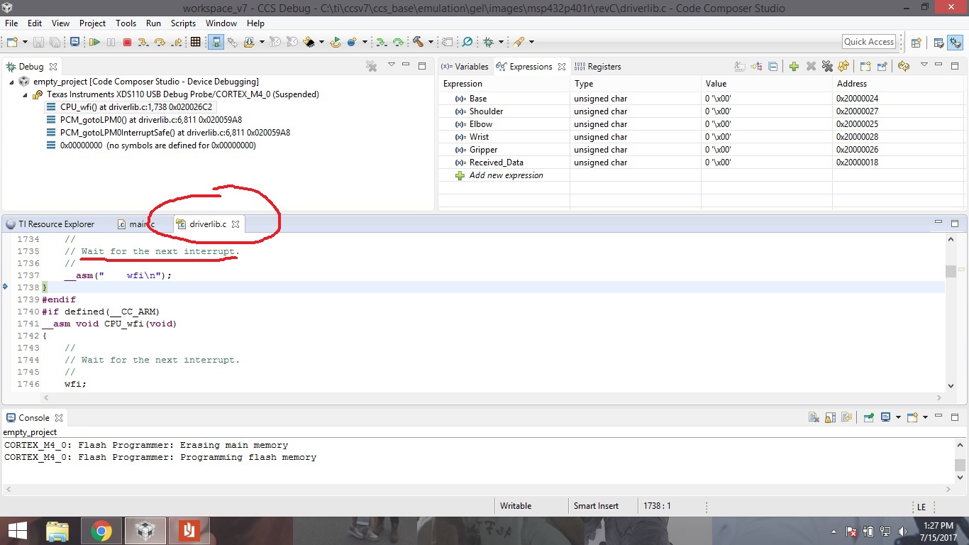
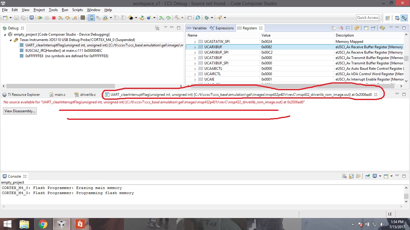
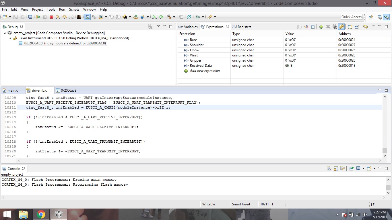
如果选择 MSP432作为接收器端、则 belowcode 是由 MSP432运行的接收器部分;
#include "driverlib.h"
#include
#include

int i = 0;
char X_Axis;
char Y_Axis;
char Z_Axis;
char Griper_Axis;
字符前导码_1 ='A';
字符前导码_2 ='B';
字符前导码_3 ='C';
字符接收到的数据= 0x00;

const eUSCI_UART_Config uartConfig =
{
EUSCI_A_UART_CLOCKSOURCE_SMCLK、 // SMCLK 时钟源
1、 // BRDIV = 8
10、 // UCxBRF =-
0、 // UCxBRS = 0xD6
EUSCI_A_UART_NO_奇 偶校验、 //无奇偶校验
EUSCI_A_UART_MSB_FIRST、 // MSB 优先
EUSCI_A_UART_One_stop_bit、 //一个停止位
EUSCI_A_UART_MODE、 // UART 模式
EUSCI_A_UART_oversampling_BAUDRATE_generation、//无过采样
};

int main (void)
{
WDT_A_HOLDTimer();

/*在 UART 模式下选择 P1.2和 P1.3 */
GPIO_setPeripheralModuleFunctionInputPin (GPIO_PORT_P3、GPIO_PIN2 | GPIO_PIN3、GPIO_PRIMARY_MODULE_Function);

CS_setDCOFrequency (1000000);

UART_initModule (EUSCI_A2_base、uartConfig); /*配置 UART 模块*/
UART_enableModule (USCI_A2_base); /*启用 UART 模块*/
UART_enableInterrupt (EUSCI_A2_base、EUSCI_A_UART_receive_interrupt);//启用中断*
INTERRUPT_enableInterrupt (INT_EUSCIA2);
interrupt_enableMaster();
interrupt_enableSlepOnIsrExit();

while (1)
{
PCM_gotoLPM0 ();
}
}

空 EUSCIA2_IRQHandler (空)
{
uint32_t status = UART_getEnabledInterruptStatus (EUSCI_A2_base);

UART_clearInterruptFlag (EUSCI_A2_base、status);

IF (STATUS 和 EUSCI_A_UART_receive_interrupt_FLAG)
{
Received_Data = UART_receiveData (EUSCI_A2_base);

if (i = 0){
if (Received_Data =前导码_1)
I = 1;
其他
I = 0;
}
否则、如果(i = 1){
if (Received_Data =前导码_2)
I = 2;
其他
I = 0;
}
否则、如果(i ==2){
if (Received_Data =前导码_3)
I = 3;
其他
I = 0;
}
否则、如果(i = 3){
x_Axis =接收到的数据;
I = 4;
}
否则、如果(i = 4){
Y_Axis =接收到的数据;
I = 5;
}
否则、如果(i == 5){
Z_Axis =接收到的数据;
I = 6;
}
否则、如果(i ==6){
夹具轴=接收到的数据;
I = 0;
}
}
interrupt_disableSlepOnIsrExit();
}