This thread has been locked.
If you have a related question, please click the "Ask a related question" button in the top right corner. The newly created question will be automatically linked to this question.
https://e2e.ti.com/support/wireless-connectivity/other-wireless-group/other-wireless/f/other-wireless-technologies-forum/1321315/cc2652p-can-t-create-custom-board-config-with-cc2652p1frgz
您好!
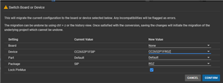
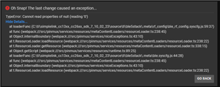
我一直在尝试基于定制板创建项目。 每当我尝试切换到 CC2652P1FRGZ 时、就无法迁移。
Resource Explorer 中的任何示例均 改用 CC2652P1FSIP 器件。
如何检查基于 CC2652P1FRGZ 创建项目?
谢谢。
尼克
您好、Nick。
对于 CC2652P1、建议使用 CC1352P1工程、例如以下示例: https://dev.ti.com/tirex/explore/node?node=A__APALJVbDifPTzAjspzfa1A__com.ti.SIMPLELINK_CC13XX_CC26XX_SDK__BSEc4rl__LATEST
如需了解更多相关信息、 请访问:https://dev.ti.com/tirex/content/simplelink_cc13xx_cc26xx_sdk_7_10_02_23/docs/zigbee/html/cc13xx_cc26xx/software-on-cc2652p.html
谢谢。 托比
尊敬的 Toby:
感谢链接。 我将把 CC1352P1用于我的 CC2652P1项目。 我还有一个问题。 SysConfig 生成的代码似乎不包括 .pRegOverrideTxStd 和 .pRegOverrideTx20。 如果我尝试将 TX 功率设置为任何超过5dBm 的值、则表示参数无效。 我之所以可以这样说、是因为 在 RFC_CMD_PROP_RADIO_DIV_SETUP_PA_t 结构中、pRegOVerrideTxStd 和.pRegOverrideTx20设置为0。 您能指出正确的方向吗? 这是我需要手动生成的东西、还是这种意外行为? 以下是我的 SysConfig 生成的内容:
// *********************************************************************************
//   RF Frontend configuration
// *********************************************************************************
// RF design based on: LAUNCHXL-CC1352P1

// TX Power tables
// The RF_TxPowerTable_DEFAULT_PA_ENTRY and RF_TxPowerTable_HIGH_PA_ENTRY macros are defined in RF.h.
// The following arguments are required:
// RF_TxPowerTable_DEFAULT_PA_ENTRY(bias, gain, boost, coefficient)
// RF_TxPowerTable_HIGH_PA_ENTRY(bias, ibboost, boost, coefficient, ldoTrim)
// See the Technical Reference Manual for further details about the "txPower" Command field.
// The PA settings require the CCFG_FORCE_VDDR_HH = 0 unless stated otherwise.

// 2400 MHz, 5 dBm
RF_TxPowerTable_Entry txPowerTable_2400_pa5[TXPOWERTABLE_2400_PA5_SIZE] =
{
    {-20, RF_TxPowerTable_DEFAULT_PA_ENTRY(6, 3, 0, 2) }, // 0x04C6
    {-18, RF_TxPowerTable_DEFAULT_PA_ENTRY(8, 3, 0, 3) }, // 0x06C8
    {-15, RF_TxPowerTable_DEFAULT_PA_ENTRY(10, 3, 0, 3) }, // 0x06CA
    {-12, RF_TxPowerTable_DEFAULT_PA_ENTRY(12, 3, 0, 5) }, // 0x0ACC
    {-10, RF_TxPowerTable_DEFAULT_PA_ENTRY(15, 3, 0, 5) }, // 0x0ACF
    {-9, RF_TxPowerTable_DEFAULT_PA_ENTRY(16, 3, 0, 5) }, // 0x0AD0
    {-6, RF_TxPowerTable_DEFAULT_PA_ENTRY(20, 3, 0, 8) }, // 0x10D4
    {-5, RF_TxPowerTable_DEFAULT_PA_ENTRY(22, 3, 0, 9) }, // 0x12D6
    {-3, RF_TxPowerTable_DEFAULT_PA_ENTRY(19, 2, 0, 12) }, // 0x1893
    {0, RF_TxPowerTable_DEFAULT_PA_ENTRY(19, 1, 0, 20) }, // 0x2853
    {1, RF_TxPowerTable_DEFAULT_PA_ENTRY(22, 1, 0, 20) }, // 0x2856
    {2, RF_TxPowerTable_DEFAULT_PA_ENTRY(25, 1, 0, 25) }, // 0x3259
    {3, RF_TxPowerTable_DEFAULT_PA_ENTRY(29, 1, 0, 28) }, // 0x385D
    {4, RF_TxPowerTable_DEFAULT_PA_ENTRY(35, 1, 0, 39) }, // 0x4E63
    {5, RF_TxPowerTable_DEFAULT_PA_ENTRY(23, 0, 0, 57) }, // 0x7217
    RF_TxPowerTable_TERMINATION_ENTRY
};

// 2400 MHz, 20 dBm
RF_TxPowerTable_Entry txPowerTable_2400_pa20[TXPOWERTABLE_2400_PA20_SIZE] =
{
    {14, RF_TxPowerTable_HIGH_PA_ENTRY(22, 3, 1, 19, 27) }, // 0x1B27D6
    {15, RF_TxPowerTable_HIGH_PA_ENTRY(26, 3, 1, 23, 27) }, // 0x1B2FDA
    {16, RF_TxPowerTable_HIGH_PA_ENTRY(30, 3, 1, 28, 27) }, // 0x1B39DE
    {17, RF_TxPowerTable_HIGH_PA_ENTRY(37, 3, 1, 39, 27) }, // 0x1B4FE5
    {18, RF_TxPowerTable_HIGH_PA_ENTRY(32, 3, 1, 35, 48) }, // 0x3047E0
    {19, RF_TxPowerTable_HIGH_PA_ENTRY(34, 3, 1, 48, 63) }, // 0x3F61E2
    {20, RF_TxPowerTable_HIGH_PA_ENTRY(53, 3, 1, 58, 63) }, // 0x3F75F5
    RF_TxPowerTable_TERMINATION_ENTRY
};


//*********************************************************************************
//  RF Setting:   Custom (100 kbps, 50 kHz Deviation, 2-GFSK, 350 kHz RX Bandwidth)
//
//  PHY:          custom2400
//  Setting file: setting_tc900_custom.json
//*********************************************************************************

// PARAMETER SUMMARY
// RX Address Mode: No address check
// Frequency (MHz): 2440.0000
// Deviation (kHz): 50.0
// Packet Length Config: Variable
// Max Packet Length: 255
// Preamble Count: 4 Bytes
// Preamble Mode: Send 0 as the first preamble bit
// RX Filter BW (kHz): 349.7
// Symbol Rate (kBaud): 100.000
// Sync Word: 0x930B51DE
// Sync Word Length: 32 Bits
// TX Power (dBm): 5
// Whitening: No whitening

// TI-RTOS RF Mode Object
RF_Mode RF_prop_custom2400_0 =
{
    .rfMode = RF_MODE_PROPRIETARY_2_4,
    .cpePatchFxn = &rf_patch_cpe_prop,
    .mcePatchFxn = 0,
    .rfePatchFxn = 0
};

// Overrides for CMD_PROP_RADIO_DIV_SETUP_PA
uint32_t pOverrides_custom2400_0[] =
{
    // override_tc900.json
    // DC/DC regulator: In Tx, use DCDCCTL5[3:0]=0x3 (DITHER_EN=0 and IPEAK=3).
    (uint32_t)0x00F388D3,
    // Tx: Configure PA ramp time, PACTL2.RC=0x2 (in ADI0, set PACTL2[4:3]=0x2)
    ADI_2HALFREG_OVERRIDE(0,16,0x8,0x0,17,0x1,0x1),
    // Rx: Set AGC reference level to 0x20 (default: 0x2E)
    HW_REG_OVERRIDE(0x609C,0x0020),
    // Rx: Set anti-aliasing filter bandwidth to 0x9 (in ADI0, set IFAMPCTL3[7:4]=0x9)
    ADI_HALFREG_OVERRIDE(0,61,0xF,0x9),
    (uint32_t)0xFFFFFFFF
};


// CMD_PROP_RADIO_DIV_SETUP_PA
// Proprietary Mode Radio Setup Command for All Frequency Bands
rfc_CMD_PROP_RADIO_DIV_SETUP_PA_t RF_cmdPropRadioDivSetup_custom2400_0 =
{
    .commandNo = 0x3807,
    .status = 0x0000,
    .pNextOp = 0,
    .startTime = 0x00000000,
    .startTrigger.triggerType = 0x0,
    .startTrigger.bEnaCmd = 0x0,
    .startTrigger.triggerNo = 0x0,
    .startTrigger.pastTrig = 0x0,
    .condition.rule = 0x1,
    .condition.nSkip = 0x0,
    .modulation.modType = 0x1,
    .modulation.deviation = 0xC8,
    .modulation.deviationStepSz = 0x0,
    .symbolRate.preScale = 0xF,
    .symbolRate.rateWord = 0x10000,
    .symbolRate.decimMode = 0x0,
    .rxBw = 0x59,
    .preamConf.nPreamBytes = 0x4,
    .preamConf.preamMode = 0x0,
    .formatConf.nSwBits = 0x20,
    .formatConf.bBitReversal = 0x0,
    .formatConf.bMsbFirst = 0x1,
    .formatConf.fecMode = 0x0,
    .formatConf.whitenMode = 0x0,
    .config.frontEndMode = 0x0,
    .config.biasMode = 0x1,
    .config.analogCfgMode = 0x0,
    .config.bNoFsPowerUp = 0x0,
    .config.bSynthNarrowBand = 0x0,
    .txPower = 0xFFFF,
    .pRegOverride = pOverrides_custom2400_0,
    .centerFreq = 0x0988,
    .intFreq = 0x0800,
    .loDivider = 0x00,
    .pRegOverrideTxStd = 0,
    .pRegOverrideTx20 = 0
};
如果在2.4GHz 下 TX 功率高于5dBm、请尝试改用 CC1352P2示例。 此帖子供参考: https://e2e.ti.com/support/wireless-connectivity/bluetooth-group/bluetooth/f/bluetooth-forum/1097448/cc2652p-tx-power-out-range-problem
是的、咨询同事后、这似乎是一个已知问题。
参考帖子: https://e2e.ti.com/support/wireless-connectivity/bluetooth-group/bluetooth/f/bluetooth-forum/1268628/cc2652p7-proprietary-2-4ghz-transmit-power-tx-to-20dbm
它需要一些额外的步骤、默认情况下 SysConfig 中未显示该 设置的主要原因是"CC2652PX 专有射频设置尚未针对高 PA 设置进行表征"。