This thread has been locked.
If you have a related question, please click the "Ask a related question" button in the top right corner. The newly created question will be automatically linked to this question.
https://e2e.ti.com/support/power-management-group/power-management/f/power-management-forum/1016791/ucc28950-gate-oscillating-in-380vdc
你(们)好
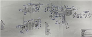
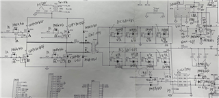
我的客户将 UCC28950用于1100W 项目、在空载条件下 、200Vdc~300Vdc 输入中的栅极波形是正常 的、但380Vdc 输入中将出现振荡。
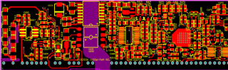
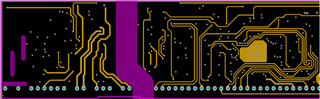
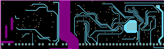
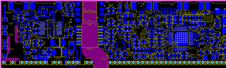
其结构和布局如下所示。 我们可以在哪里进行修改以减少此问题? 谢谢。
您好!
听起来、除了380V 之外、该设计在每个点都是稳定的
您可能希望让他检查他的电压环路补偿。
1. 您可以使用 Webench 或 Excel 设计工具、该工具可在以下链接中找到。 https://www.ti.com/product/UCC28950?keyMatch=UCC28950&tisearch=search-everything&usecase=GPN#design-development##design-tools-simulation
此外、还有一份应用手册、其中介绍了如何计算 UCC28950和 UCC28951器件的电压环路、您可以通过以下链接找到该应用手册、该链接可能对您的客户有用。 https://www.ti.com/lit/pdf/slua560
3. 您可能需要向他发送 UCC28950EVM https://www.ti.com/lit/pdf/sluub02 、以便他可以对其进行比较并将其与设计波形进行比较。
答:用户指南中还有一个经过验证的布局、也可用作比较其波形的参考。
此致、
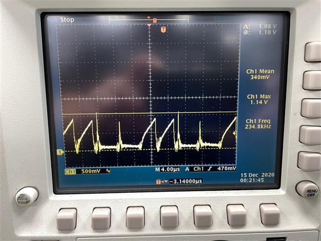
输入电压为380V 时、可以正常工作、但负载电压为12V、满负载需要90A、30A 正常工作、但超过35A 时、CS 波形不稳定。
如何减少此问题? 谢谢。
嗨、Rock
负载高于35A 时、电压环路看起来不稳定、CS 信号从50%占空比跳转到窄占空比。 您能否让客户获取电压环路的增益/相位曲线?
同时、我需要更多波形来澄清问题、
UCC28950和 CS 信号的引脚输出 OUT/OUTA。
云生