This thread has been locked.

If you have a related question, please click the "Ask a related question" button in the top right corner. The newly created question will be automatically linked to this question.

[参考译文] UCC28500:正向辅助电源设计

Guru**** 2382480 points
Other Parts Discussed in Thread: UCC28500
请注意,本文内容源自机器翻译,可能存在语法或其它翻译错误,仅供参考。如需获取准确内容,请参阅链接中的英语原文或自行翻译。

https://e2e.ti.com/support/power-management-group/power-management/f/power-management-forum/723752/ucc28500-forward-auxiliary-power-design

器件型号:UCC28500

您好、TI、

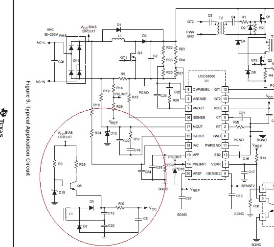
下面的电路是来自 UCC28500数据表第13页的设计示例。

下面是我的问题:辅助电源电路如何工作? D5和 D7的设计与标准正向结构不同。 我猜是电路启动时、Vccbias 会将 C6和 C12+C20充电至15V。 然后 UCC28500开始工作、并通过 L1 (变压器)为 C12充电至15V、这将使 C12 + C20变为30V (15V+15V)并强制 Q5关闭。 C6也会充电至30V 吗? 30V Vcc 将烧毁 PWM IC?  

谢谢。

  • 请注意,本文内容源自机器翻译,可能存在语法或其它翻译错误,仅供参考。如需获取准确内容,请参阅链接中的英语原文或自行翻译。
    您好、Ginger、

    Vcc 引脚有一个内部钳位器件。 Vcc 引脚由 R10供电、这将限制流入内部钳位的电流并防止 Vcc 引脚过压。

    此致

    Peter