This thread has been locked.
If you have a related question, please click the "Ask a related question" button in the top right corner. The newly created question will be automatically linked to this question.
你好。
我修改了TI的原先使用看门狗进行中断的程序,原先通过WDCR寄存器设置定时时间,等到计数溢出进入中断使得WakeCount自加1,。
现在我修改了它的代码如下所示,使其计数溢出后进入复位代码,即产生WRST信号复位程序,理论上我的LoopCount会不断自加,当没有喂狗(程序中未设置喂狗),就会复位程序,LoopCount就会清零,
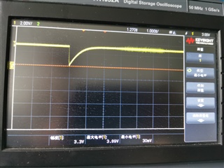
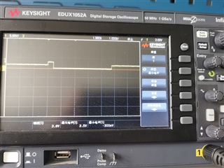
但是运行下面代码后LoopCount只变化一次就就固定在一个数值不在变化。我在程序的I函数nitPieVectTable();处打断点,程序点击运行第一次跳到此处,但是理论看门狗复位后应该再次跳到断点处,可是点击后没有反应,运行三角按钮依旧是灰色状态。请教一下这是哪里出了问题?
感谢!
#include "DSP2833x_Device.h" // Headerfile Include File #include "DSP2833x_Examples.h" // Examples Include File #include "leds.h" // Global variables for this example Uint32 WakeCount; Uint32 LoopCount; extern Uint16 RamfuncsLoadStart; extern Uint16 RamfuncsLoadEnd; extern Uint16 RamfuncsRunStart; void main(void) { // Step 1. Initialize System Control: // PLL, WatchDog, enable Peripheral Clocks // This example function is found in the DSP2833x_SysCtrl.c file. InitSysCtrl(); // Step 2. Initalize GPIO: // This example function is found in the DSP2833x_Gpio.c file and // illustrates how to set the GPIO to it's default state. // InitGpio(); // Skipped for this example // Step 3. Clear all interrupts and initialize PIE vector table: // Disable CPU interrupts DINT; // Initialize PIE control registers to their default state. // The default state is all PIE interrupts disabled and flags // are cleared. // This function is found in the DSP2833x_PieCtrl.c file. InitPieCtrl(); MemCopy(&RamfuncsLoadStart, &RamfuncsLoadEnd, &RamfuncsRunStart); InitFlash(); // Disable CPU interrupts and clear all CPU interrupt flags: IER = 0x0000; IFR = 0x0000; // Initialize the PIE vector table with pointers to the shell Interrupt // Service Routines (ISR). // This will populate the entire table, even if the interrupt // is not used in this example. This is useful for debug purposes. // The shell ISR routines are found in DSP2833x_DefaultIsr.c. // This function is found in DSP2833x_PieVect.c. InitPieVectTable(); // Step 4. Initialize all the Device Peripherals: // This function is found in DSP2833x_InitPeripherals.c // InitPeripherals(); // Not required for this example LED_Init(); // Step 5. User specific code, enable interrupts: // Clear the counters WakeCount = 0; // Count interrupts LoopCount = 0; // Count times through idle loop // Connect the watchdog to the WAKEINT interrupt of the PIE // Write to the whole SCSR register to avoid clearing WDOVERRIDE bit // EALLOW; // SysCtrlRegs.SCSR = BIT1; // EDIS; // Reset the watchdog counter // ServiceDog(); // Enable the watchdog EALLOW; SysCtrlRegs.WDCR = 0x0028; SysCtrlRegs.SCSR = 0; EDIS; //复位程序配置 // ServiceDog(); // MemCopy(&RamfuncsLoadStart, &RamfuncsLoadEnd, &RamfuncsRunStart); // InitFlash(); // Step 6. IDLE loop. Just sit and loop forever (optional): for(;;) { LoopCount++; // Uncomment ServiceDog to just loop here // Comment ServiceDog to take the WAKEINT instead // ServiceDog(); // 检验复位程序; // if(LoopCount>2000) // { // GpioDataRegs.GPACLEAR.bit.GPIO0=1; // DSP28x_usDelay(100); // EALLOW; // SysCtrlRegs.WDCR = 0x0000; // EDIS; // } } }
LoopCount只变化一次就就固定在一个数值不在变化。
这里这个参数是固定在一个随机的数值,还是一个固定的数值?
你好,是一个随机数值,InitSysCtrl();函数中先对看门狗进行了失能。之后我配置SCSR寄存器的OVERRIDE为0,当复位程序(是不是就是跳到main开头位置执行)时,也可以继续失能配置一系列初始化。结合中断程序我是这样理解的。
能否测试一下复位的时候是否复位引脚上有下拉电平?
有没有断点+单步的方式测试程序运行顺序是否正确?
另外,我怀疑你描述的内容是不是因为复位之后芯片与CCS重新连接导致的,芯片复位后仿真会断开
我在程序的I函数nitPieVectTable();处打断点,程序点击运行第一次跳到此处,但是理论看门狗复位后应该再次跳到断点处,可是点击后没有反应,运行三角按钮依旧是灰色状态。请教一下这是哪里出了问题?
你好,我测试了一下复位的电平信号,采集单个信号,运行程序后复位端口的波形如下图一所示。同时,我使用配置gpio0口来进行电平检测如图二,(l理论上若是复位了电平信号应该周期性高低),根据你指点的复位后仿真会断开,所以我拔掉JTAG接口,重启开发板,用示波器测试GPIO0口,电平没有变化(试了多次,貌似只有插上仿真器的时候执行才出现图二
#include "DSP2833x_Device.h" // Headerfile Include File #include "DSP2833x_Examples.h" // Examples Include File #include "leds.h" // Global variables for this example Uint32 WakeCount; Uint32 LoopCount; typedef int16 bool_t; extern Uint16 RamfuncsLoadStart; extern Uint16 RamfuncsLoadEnd; extern Uint16 RamfuncsRunStart; void main(void) { // Step 1. Initialize System Control: // PLL, WatchDog, enable Peripheral Clocks // This example function is found in the DSP2833x_SysCtrl.c file. InitSysCtrl(); // Step 2. Initalize GPIO: // This example function is found in the DSP2833x_Gpio.c file and // illustrates how to set the GPIO to it's default state. InitGpio(); // Skipped for this example // Step 3. Clear all interrupts and initialize PIE vector table: // Disable CPU interrupts DINT; // Initialize PIE control registers to their default state. // The default state is all PIE interrupts disabled and flags // are cleared. // This function is found in the DSP2833x_PieCtrl.c file. InitPieCtrl(); MemCopy(&RamfuncsLoadStart, &RamfuncsLoadEnd, &RamfuncsRunStart); InitFlash(); // Disable CPU interrupts and clear all CPU interrupt flags: IER = 0x0000; IFR = 0x0000; // Initialize the PIE vector table with pointers to the shell Interrupt // Service Routines (ISR). // This will populate the entire table, even if the interrupt // is not used in this example. This is useful for debug purposes. // The shell ISR routines are found in DSP2833x_DefaultIsr.c. // This function is found in DSP2833x_PieVect.c. InitPieVectTable(); // Step 4. Initialize all the Device Peripherals: LED_Init(); // Clear the counters WakeCount = 0; // Count interrupts LoopCount = 0; // Count times through idle loop GpioDataRegs.GPASET.bit.GPIO0=1; DSP28x_usDelay(10000); // Reset the watchdog counter ServiceDog(); // Enable the watchdog EALLOW; SysCtrlRegs.WDCR = 0x0028; SysCtrlRegs.SCSR = 0; EDIS; // Step 6. IDLE loop. Just sit and loop forever (optional): for(;;) { LoopCount++; // Uncomment ServiceDog to just loop here // Comment ServiceDog to take the WAKEINT instead // ServiceDog(); DSP28x_usDelay(100); GpioDataRegs.GPACLEAR.bit.GPIO0=1; DSP28x_usDelay(100); } }
额,我大概发现你的问题了。
不知道你的代码有没有上传错误,做测试的时候是不是按照第二次上传的代码测试的?
如果是按照第二次的代码测试的,那么你的代码中喂狗的语句放置的位置是错误的,应该在for循环中喂狗,而不是在程序中初始化完成之后就喂狗。这样的话等于只进行了一次喂狗,而没有重复喂狗。
但是在没有喂狗的情况下,为什么loopcount会是一个固定的随机值,这点我没想明白。猜测是复位之后loopcount被随机了一个值,而虽然程序中有对loopcount进行赋值0的操作,可能复位频率太快,CCS检测不到初始化0的值。
你好,Green。示波器测试是按第二次上传代码做的 ,因为我是按照这个教程做的 看门狗复位教程 确实可能是复位太快导致CCS检测不到,但是我的GPIO0口为什么也只是刷新一次。(理论应该是和教程描述的一样不断跳变)。
问题二:当我拔掉仿真器接口运行flash中的程序时,肉眼看不见连接在GPIO0口的led灯闪烁,也无法在示波器上检测到电平变化。
1、我的猜测是程序根本没执行到for循环,所以也就没有GPIOclear的执行,所以GPIO一直是高电平。
2、同1中的解释,因为没有执行GPIO拉低的代码,所以看不见LED闪烁(如果示波器测出来一直是高电平的话)
你好,Green, 我验证了一下你的猜测,应该是程序程序速度太快,所以看不见。主频150Mhz的执行速度,我单步执行(F6),进入到for循环是可以观察到led灯状态的切换,正常运行你看不见的,无论我在循环中是先打开还是先关闭led,结果都是一直常亮,应该是程序运行速度过快,看不到切块状态。我的猜测是否合理呢?
那也有可能,我的猜测是基于程序在看门狗计数器计满之前还没有执行到GPIOclear,如果程序能执行到GPIOclear,那应该是可以被拉低的。
但是这个拉低的脉冲长度用肉眼肯定是没办法看到的,只能单步或者用示波器才能观测到。
你好,Green。 我貌似发现了新的问题,上面的猜想应该是不对的,我使用TI的F28335.cmd 将程序烧录到内部flash中,CCS也出现擦除SectorA-H窗口过程,然后在该模式下启用单步调试功能,示波器检测到GPIO电平管脚切换。上面猜测太快,但是我拔掉JTAG后,重新上电开发板。用示波器测试GPIO0的电平管脚没有变化。原来是程序并没有烧录进内部flash中,我用其他例程测试也发现断电重新上电后flash中的程序貌似也消失了,什么情况下会导致这个问题,我现在不确定是不是我修改了F28335.cmd的内容导致的(运行看门狗添加ramfunction的字段)内部flash损坏之类的。(现在开发板还有一个现象就是GPIO0,之前连接led的那个管脚有很微弱的灯光(最左边的那个led灯),但是我烧录其他例程不涉及对它的操作,会是什么原因呢?)