This thread has been locked.
If you have a related question, please click the "Ask a related question" button in the top right corner. The newly created question will be automatically linked to this question.
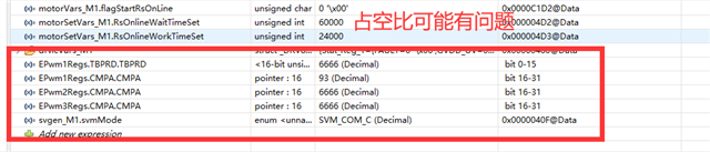
我用的是主控LAUNCHXL-F2837D 驱动板是drv8301—REVB 在进行用户指南移植过后,在根据指南中第一级增量构建中三相PWM占空比不等于50% CMPA不等于TBPRD的一半,还有电压偏执不等于0 。为什么?
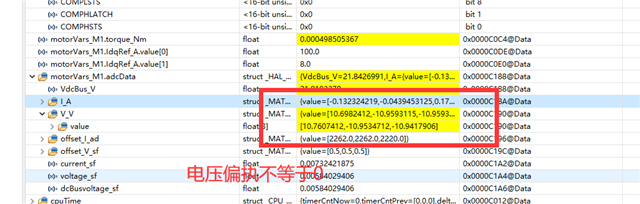
你好,请问一下说这个具体文件是问的用户指南吗?还是程序文件? 用户指南是这个链接Universal Motor Control Project and Lab User’s Guide (ti.com.cn),程序文件是用的C2000motorcontrol/solution/universal_lab
你好 我是根据User’s Guide Motor Control SDK Universal Project and Lab 这个文档对 建立关于f28379d的工程,我个人也是也认为i是pwm配置出现了问题,我去掉驱动器,只用控制板去测量引脚输出的pwm的电压显示为0。
下面是我修改的相关部分的代码
void HAL_setupPWMs(HAL_MTR_Handle handle) { HAL_MTR_Obj *obj = (HAL_MTR_Obj *)handle; uint16_t cnt; uint16_t pwmPeriodCycles = (uint16_t)(USER_M1_PWM_TBPRD_NUM); uint16_t numPWMTicksPerISRTick = USER_M1_NUM_PWM_TICKS_PER_ISR_TICK; // disable the ePWM module time base clock sync signal // to synchronize all of the PWMs SysCtl_disablePeripheral(SYSCTL_PERIPH_CLK_TBCLKSYNC); // turns off the outputs of the EPWM peripherals which will put the power // switches into a high impedance state. EPWM_forceTripZoneEvent(obj->pwmHandle[0], EPWM_TZ_FORCE_EVENT_OST); EPWM_forceTripZoneEvent(obj->pwmHandle[1], EPWM_TZ_FORCE_EVENT_OST); EPWM_forceTripZoneEvent(obj->pwmHandle[2], EPWM_TZ_FORCE_EVENT_OST); #if defined(BSXL8323RS_REVA) || defined(BSXL8323RH_REVB) || \ defined(BSXL8353RS_REVA) || defined(BSXL8316RT_REVA) || \ defined(BSXL3PHGAN_REVA) || defined(HVMTRPFC_REV1P1) || \ defined(BSXL8301_REVB) for(cnt=0; cnt<3; cnt++) { // setup the Time-Base Control Register (TBCTL) EPWM_setTimeBaseCounterMode(obj->pwmHandle[cnt], EPWM_COUNTER_MODE_UP_DOWN); EPWM_disablePhaseShiftLoad(obj->pwmHandle[cnt]); EPWM_setPeriodLoadMode(obj->pwmHandle[cnt], EPWM_PERIOD_DIRECT_LOAD); //EPWM_enableSyncOutPulseSource(obj->pwmHandle[cnt], // EPWM_SYNC_OUT_PULSE_ON_SOFTWARE); EPWM_setSyncOutPulseMode(obj->pwmHandle[cnt], EPWM_SYNC_OUT_PULSE_ON_SOFTWARE); EPWM_setClockPrescaler(obj->pwmHandle[cnt], EPWM_CLOCK_DIVIDER_1, EPWM_HSCLOCK_DIVIDER_1); EPWM_setCountModeAfterSync(obj->pwmHandle[cnt], EPWM_COUNT_MODE_UP_AFTER_SYNC); EPWM_setEmulationMode(obj->pwmHandle[cnt], EPWM_EMULATION_FREE_RUN); // setup the Timer-Based Phase Register (TBPHS) EPWM_setPhaseShift(obj->pwmHandle[cnt], 0); // setup the Time-Base Counter Register (TBCTR) EPWM_setTimeBaseCounter(obj->pwmHandle[cnt], 0); // setup the Time-Base Period Register (TBPRD) // set to zero initially EPWM_setTimeBasePeriod(obj->pwmHandle[cnt], 0); // setup the Counter-Compare Control Register (CMPCTL) EPWM_setCounterCompareShadowLoadMode(obj->pwmHandle[cnt], EPWM_COUNTER_COMPARE_A, EPWM_COMP_LOAD_ON_CNTR_ZERO); EPWM_setCounterCompareShadowLoadMode(obj->pwmHandle[cnt], EPWM_COUNTER_COMPARE_B, EPWM_COMP_LOAD_ON_CNTR_ZERO); EPWM_setCounterCompareShadowLoadMode(obj->pwmHandle[cnt], EPWM_COUNTER_COMPARE_C, EPWM_COMP_LOAD_ON_CNTR_ZERO); EPWM_setCounterCompareShadowLoadMode(obj->pwmHandle[cnt], EPWM_COUNTER_COMPARE_D, EPWM_COMP_LOAD_ON_CNTR_ZERO); #else //!MOTOR1_ISBLDC #if defined(MOTOR1_DCLINKSS) ....... #else // !(MOTOR1_DCLINKSS) // setup the Action-Qualifier Output A Register (AQCTLA) EPWM_setActionQualifierAction(obj->pwmHandle[cnt], EPWM_AQ_OUTPUT_A, EPWM_AQ_OUTPUT_HIGH, EPWM_AQ_OUTPUT_ON_TIMEBASE_UP_CMPA); EPWM_setActionQualifierAction(obj->pwmHandle[cnt], EPWM_AQ_OUTPUT_A, EPWM_AQ_OUTPUT_HIGH, EPWM_AQ_OUTPUT_ON_TIMEBASE_PERIOD); EPWM_setActionQualifierAction(obj->pwmHandle[cnt], EPWM_AQ_OUTPUT_A, EPWM_AQ_OUTPUT_LOW, EPWM_AQ_OUTPUT_ON_TIMEBASE_DOWN_CMPA); EPWM_setActionQualifierAction(obj->pwmHandle[cnt], EPWM_AQ_OUTPUT_A, EPWM_AQ_OUTPUT_LOW, EPWM_AQ_OUTPUT_ON_TIMEBASE_ZERO); #endif // !(MOTOR1_DCLINKSS) // setup the Dead-Band Generator Control Register (DBCTL) EPWM_setDeadBandDelayMode(obj->pwmHandle[cnt], EPWM_DB_RED, true); EPWM_setDeadBandDelayMode(obj->pwmHandle[cnt], EPWM_DB_FED, true); // select EPWMA as the input to the dead band generator EPWM_setRisingEdgeDeadBandDelayInput(obj->pwmHandle[cnt], EPWM_DB_INPUT_EPWMA); // configure the right polarity for active high complementary config. EPWM_setDeadBandDelayPolarity(obj->pwmHandle[cnt], EPWM_DB_RED, EPWM_DB_POLARITY_ACTIVE_HIGH); EPWM_setDeadBandDelayPolarity(obj->pwmHandle[cnt], EPWM_DB_FED, EPWM_DB_POLARITY_ACTIVE_LOW); // setup the Dead-Band Rising Edge Delay Register (DBRED) EPWM_setRisingEdgeDelayCount(obj->pwmHandle[cnt], MTR1_PWM_DBRED_CNT); // setup the Dead-Band Falling Edge Delay Register (DBFED) EPWM_setFallingEdgeDelayCount(obj->pwmHandle[cnt], MTR1_PWM_DBFED_CNT); #endif //!MOTOR1_ISBLDC // setup the PWM-Chopper Control Register (PCCTL) EPWM_disableChopper(obj->pwmHandle[cnt]); // setup the Trip Zone Select Register (TZSEL) EPWM_disableTripZoneSignals(obj->pwmHandle[cnt], HAL_TZSEL_SIGNALS_ALL); } #if defined(MOTOR1_ISBLDC) .......... #elif ......... #else //!(MOTOR1_ISBLDC || MOTOR1_DCLINKSS) // setup the Event Trigger Selection Register (ETSEL) EPWM_setInterruptSource(obj->pwmHandle[0], EPWM_INT_TBCTR_ZERO); EPWM_enableInterrupt(obj->pwmHandle[0]); EPWM_setADCTriggerSource(obj->pwmHandle[0], EPWM_SOC_A, EPWM_SOC_TBCTR_D_CMPC); EPWM_enableADCTrigger(obj->pwmHandle[0], EPWM_SOC_A); #endif // !(MOTOR1_ISBLDC || MOTOR1_DCLINKSS) // setup the Event Trigger Prescale Register (ETPS) if(numPWMTicksPerISRTick > 15) { EPWM_setInterruptEventCount(obj->pwmHandle[0], 15); EPWM_setADCTriggerEventPrescale(obj->pwmHandle[0], EPWM_SOC_A, 15); EPWM_setADCTriggerEventPrescale(obj->pwmHandle[0], EPWM_SOC_B, 15); } else if(numPWMTicksPerISRTick < 1) { EPWM_setInterruptEventCount(obj->pwmHandle[0], 1); EPWM_setADCTriggerEventPrescale(obj->pwmHandle[0], EPWM_SOC_A, 1); EPWM_setADCTriggerEventPrescale(obj->pwmHandle[0], EPWM_SOC_B, 1); } else { EPWM_setInterruptEventCount(obj->pwmHandle[0], numPWMTicksPerISRTick); EPWM_setADCTriggerEventPrescale(obj->pwmHandle[0], EPWM_SOC_A, numPWMTicksPerISRTick); EPWM_setADCTriggerEventPrescale(obj->pwmHandle[0], EPWM_SOC_B, numPWMTicksPerISRTick); } // setup the Event Trigger Clear Register (ETCLR) EPWM_clearEventTriggerInterruptFlag(obj->pwmHandle[0]); EPWM_clearADCTriggerFlag(obj->pwmHandle[0], EPWM_SOC_A); EPWM_clearADCTriggerFlag(obj->pwmHandle[0], EPWM_SOC_B); // since the PWM is configured as an up/down counter, the period register is // set to one-half of the desired PWM period EPWM_setTimeBasePeriod(obj->pwmHandle[0], pwmPeriodCycles); EPWM_setTimeBasePeriod(obj->pwmHandle[1], pwmPeriodCycles); EPWM_setTimeBasePeriod(obj->pwmHandle[2], pwmPeriodCycles); // write the PWM data value for ADC trigger EPWM_setCounterCompareValue(obj->pwmHandle[0], EPWM_COUNTER_COMPARE_C, 10); // enable the ePWM module time base clock sync signal SysCtl_enablePeripheral(SYSCTL_PERIPH_CLK_TBCLKSYNC); return; } // end of HAL_setupPWMs() function static inline void HAL_writePWMData(HAL_MTR_Handle handle, HAL_PWMData_t *pPWMData) { HAL_MTR_Obj *obj = (HAL_MTR_Obj *)handle; float32_t period = (float32_t)(EPWM_getTimeBasePeriod(obj->pwmHandle[0])); uint16_t pwmCnt; for(pwmCnt=0; pwmCnt<3; pwmCnt++) { // compute the value float32_t V_pu = -pPWMData->Vabc_pu.value[pwmCnt]; // Negative float32_t V_sat_pu = __fsat(V_pu, 0.5, -0.5); // -0.5~0.5 float32_t V_sat_dc_pu = V_sat_pu + 0.5; // 0~1.0 pPWMData->cmpValue[pwmCnt] = (int16_t)(V_sat_dc_pu * period); // if(pPWMData->cmpValue[pwmCnt] < pPWMData->minCMPValue) { pPWMData->cmpValue[pwmCnt] = pPWMData->minCMPValue; } // write the PWM data value EPWM_setCounterCompareValue(obj->pwmHandle[pwmCnt], EPWM_COUNTER_COMPARE_A, pPWMData->cmpValue[pwmCnt]); EPWM_setCounterCompareValue(obj->pwmHandle[pwmCnt], EPWM_COUNTER_COMPARE_B, pPWMData->cmpValue[pwmCnt]); } return; } // end of HAL_writePWMData() function void runMotor1OffsetsCalculation(MOTOR_Handle handle) { ................. ADC_setPPBReferenceOffset(MTR1_IU_ADC_BASE, MTR1_IU_ADC_PPB_NUM, 0); ADC_setPPBReferenceOffset(MTR1_IV_ADC_BASE, MTR1_IV_ADC_PPB_NUM, 0); ADC_setPPBReferenceOffset(MTR1_IW_ADC_BASE, MTR1_IW_ADC_PPB_NUM, 0); obj->adcData.offset_I_ad.value[0] = obj->adcData.offset_I_ad.value[0] * obj->adcData.current_sf; obj->adcData.offset_I_ad.value[1] = obj->adcData.offset_I_ad.value[1] * obj->adcData.current_sf; obj->adcData.offset_I_ad.value[2] = obj->adcData.offset_I_ad.value[2] * obj->adcData.current_sf; // Set the 3-phase output PWMs to 50% duty cycle obj->pwmData.Vabc_pu.value[0] = 0.0f; obj->pwmData.Vabc_pu.value[1] = 0.0f; obj->pwmData.Vabc_pu.value[2] = 0.0f; // obj->pwmData.Vabc_pu.value[0] = 0.4f; // obj->pwmData.Vabc_pu.value[1] = 0.5f; // obj->pwmData.Vabc_pu.value[2] = 0.5f; ...................... } __interrupt void motor1CtrlISR(void) {................ #if(DMC_BUILDLEVEL == DMC_LEVEL_1) // output 50% obj->pwmData.Vabc_pu.value[0] = 0.0f; obj->pwmData.Vabc_pu.value[1] = 0.0f; obj->pwmData.Vabc_pu.value[2] = 0.0f; // obj->pwmData.Vabc_pu.value[0] = 0.5f; // obj->pwmData.Vabc_pu.value[1] = 0.5f; // obj->pwmData.Vabc_pu.value[2] = 0.5f; #endif }
参考下工程师的回复:
Currently, the Universal Motor Control doesn't support f28379d and DRV8301 kit, you need to follow the lab user's guide to port this project for f28379d. Make sure that you change the configuration correctly for f28379d and drv8301 kit.
Universal Project and Lab User’s Guide: https://www.ti.com/lit/spruj26