

Part Number: TMS320F28374S
使用 测试连接正常,但是下载程序时报错
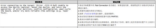
Error connecting to the target:
(Error -2131 @ 0x0)
Unable to access device register. Reset the device, and retry the operation. If
error persists, confirm configuration, power-cycle the board, and/or try
more reliable JTAG settings (e.g. lower TCLK).
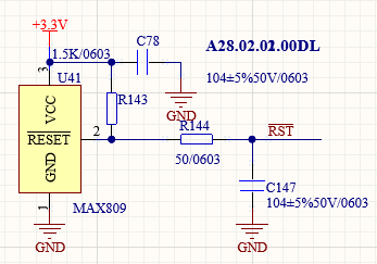
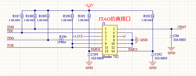
检查了供电3.3和1.2没有问题,晶振正常,复位脚正常,Jtag各上拉电压正常,还有哪里可能会有问题?部分原理图如下。

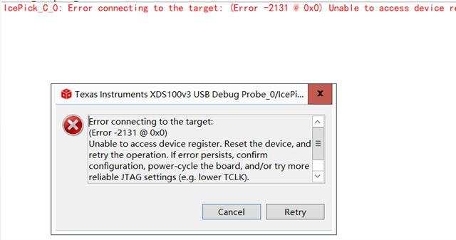
 ,在进行手动连接时同样报2131错误