This thread has been locked.

If you have a related question, please click the "Ask a related question" button in the top right corner. The newly created question will be automatically linked to this question.

I2C通讯的NACK位该如何产生?


hi,every one:

我最近在学习如何使用硬件I2C通讯来读取MPU6050,

但是遇到了一些问题:

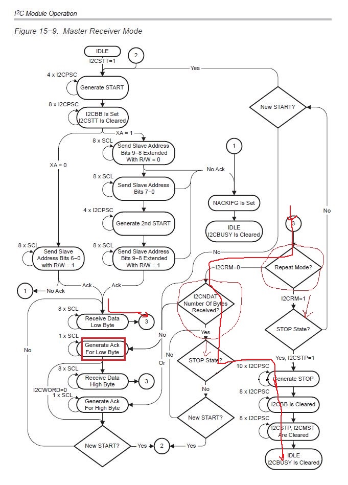
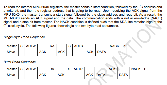
(1)MPU6050的读时序中,结束位产生之前需要产生一个NACK位,也就是将SCL拉高,翻了几遍手册,还是摸不着头脑该怎样产生这个NACK位,所以特来求助一下大家。

(2)同样是MPU6050的写时序,将I2CSTT开始位置位后并顺利发送了地址和第一帧数据,如果我想继续发送一帧数据,是不是需要要将TXRDYIFG置位?     

                                                                                                                    谢谢!

                                                                                                                    2017年4月30日23:48:18

                                                                                                                    TAMK

  • 问题(1):

    你所提的需求,可以支持。根据德州仪器MSP430芯片的官方文档《MSP430x1xx Family User's Guide (Rev. F)》中15.2.4章节,Figure 15-9. Master Receiver Mode(上图) 可以看出,当数据主机接收完最后一个byte之后,不会再产生ACK信号,直接会根据Repeat Mode决定是手动或者自动发送Stop信号。 建议直接采用I2CRM = 0的模式,此模式下,配置I2CTCTL = I2CSTT+I2CSTP;  当I2CNDAT个数据接收完之后,即自动发送Stop信号,最后一个数据不会产生ACK,即NACK。

    问题(2):

    继续发送数据无需置位TXRDYIFG。TXRDYIFG是发送完成标志,应该是用TXRDYIFG来判断上次发送是否完成。关于I2C的使用,可以参照下面的官方例程 fet140_i2c_13.c

    #include <msp430.h>

    void Commstart (void);
    void RXBytes (void);
    void TXBytes (void);
    volatile unsigned int i;

    int main(void)
    {
         WDTCTL = WDTPW | WDTHOLD; // Disable the Watchdog.
         P3SEL |= 0x0a; // Assign I2C pins to module
         U0CTL |= I2C + SYNC; // Switch USART0 to I2C mode
         U0CTL &= ~I2CEN; // Recommended init procedure
         I2CTCTL = I2CSSEL_2; // SMCLK
         I2CNDAT = 0x03; // Transmit Three byte
         I2CSA = 0x4C; // Slave address
         U0CTL |= I2CEN; // Enable I2C, 7 bit addr,
         Commstart(); // MSP430 sends a 0x00 to the DAC
         while(1)
         {
              RXBytes(); // RX 3 Bytes (MSB, LSB, Control)
              TXBytes(); // TX 3 Bytes (Control, MSB, LSB)
         }
    }


    void Commstart (void)
    {
         U0CTL |= MST; // Master mode
         I2CTCTL |= I2CSTT+I2CSTP+I2CTRX; // Initiate transfer
         while ((I2CIFG & TXRDYIFG) == 0); // Wait for transmitter to be ready
         I2CDRB = 0x10; // Load Control Byte
         while ((I2CIFG & TXRDYIFG) == 0); // Wait for transmitter to be ready
         I2CDRB = 0x00; // Load MSByte
         while ((I2CIFG & TXRDYIFG) == 0); // Wait for transmitter to be ready
         I2CDRB = 0x00; // Load LSByte
         while ((I2CTCTL & I2CSTP) == 0x02); // To prevent Arbitration Lost
    }

    void RXBytes (void)
    {
         unsigned char ctlbyte;
         U0CTL |= MST; // Master mode
         I2CTCTL = I2CSTT+I2CSTP; // Initiate transfer
         while ((I2CIFG & RXRDYIFG) == 0); // Wait for Receiver to be ready
         i = I2CDRB; // Receive MSByte from DAC
         i = i << 8;
         while ((I2CIFG & RXRDYIFG) == 0); // Wait for Receiver to be ready
         i = i + I2CDRB; // Receive LSByte from DAC
         while ((I2CIFG & RXRDYIFG) == 0); // Wait for Receiver to be ready
         ctlbyte = I2CDRB; // Receive ControlByte from DAC
         while ((I2CTCTL & I2CSTP) == 0x02); // Wait for Stop Condition
    }

    void TXBytes (void)
    {
         i = i + 1;
         U0CTL |= MST; // Master mode
         I2CTCTL |= I2CSTT+I2CSTP+I2CTRX; // Initiate transfer
         while ((I2CIFG & TXRDYIFG) == 0); // Wait for transmitter to be ready
         I2CDRB = 0x10; // Load Control Byte
         while ((I2CIFG & TXRDYIFG) == 0); // Wait for transmitter to be ready
         I2CDRB = i >> 8; // Load MSByte
         while ((I2CIFG & TXRDYIFG) == 0); // Wait for transmitter to be ready
         I2CDRB = i & 0x00FF; // Load LSByte
         while ((I2CTCTL & I2CSTP) == 0x02); // Wait for Stop Condition
    }

    如有相关问题,建议参考TI官方文档和相关例程,均可于TI.com免费下载。

    MSP430x1xx.pdf
  • 如果您认为此问题已被解答,请在“这是否解答您的问题” 后,点击“”按钮。 感谢您对TI的大力支持!