This thread has been locked.

If you have a related question, please click the "Ask a related question" button in the top right corner. The newly created question will be automatically linked to this question.

MSP430G2553 I2C SCLK 波型異常

Other Parts Discussed in Thread: MSP430G2553, FDC2212

各位前輩與先進您好,

目前使用MSP430G2553來進行I2C通訊,

程式代碼:

if ( TI_USCI_I2C_slave_present(0x2a) ) ;// 這行回傳值為"1"

while ( TI_USCI_I2C_notready() );     // wait for bus to be free

TI_USCI_I2C_transmitinit(0x2a,ISPEED);

array[0] = 0x08; array[1]=0x12;   array[2]= 0x34;     // RCOUNT = ffff

while ( TI_USCI_I2C_notready() );     // wait for bus to be free

TI_USCI_I2C_transmit(3,array);       // transmit the first three bytes from array

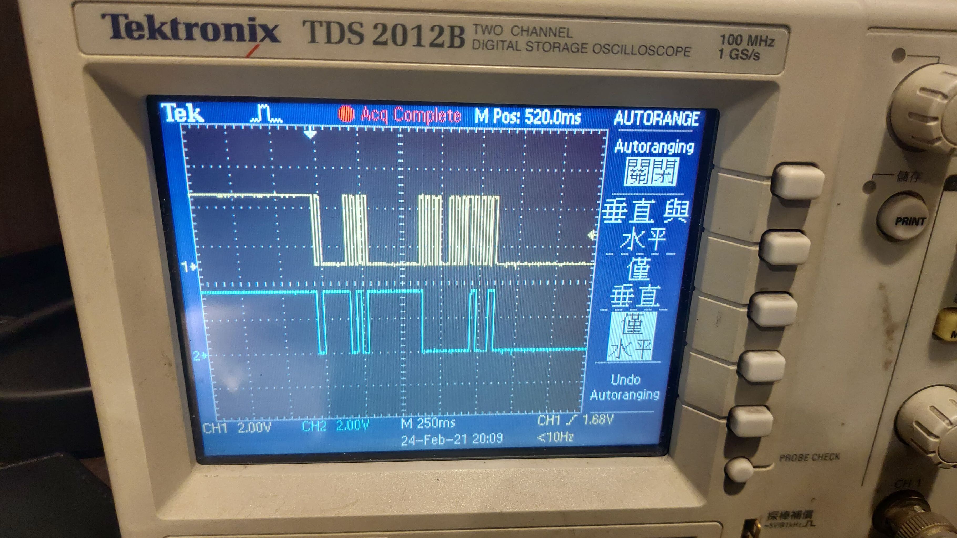
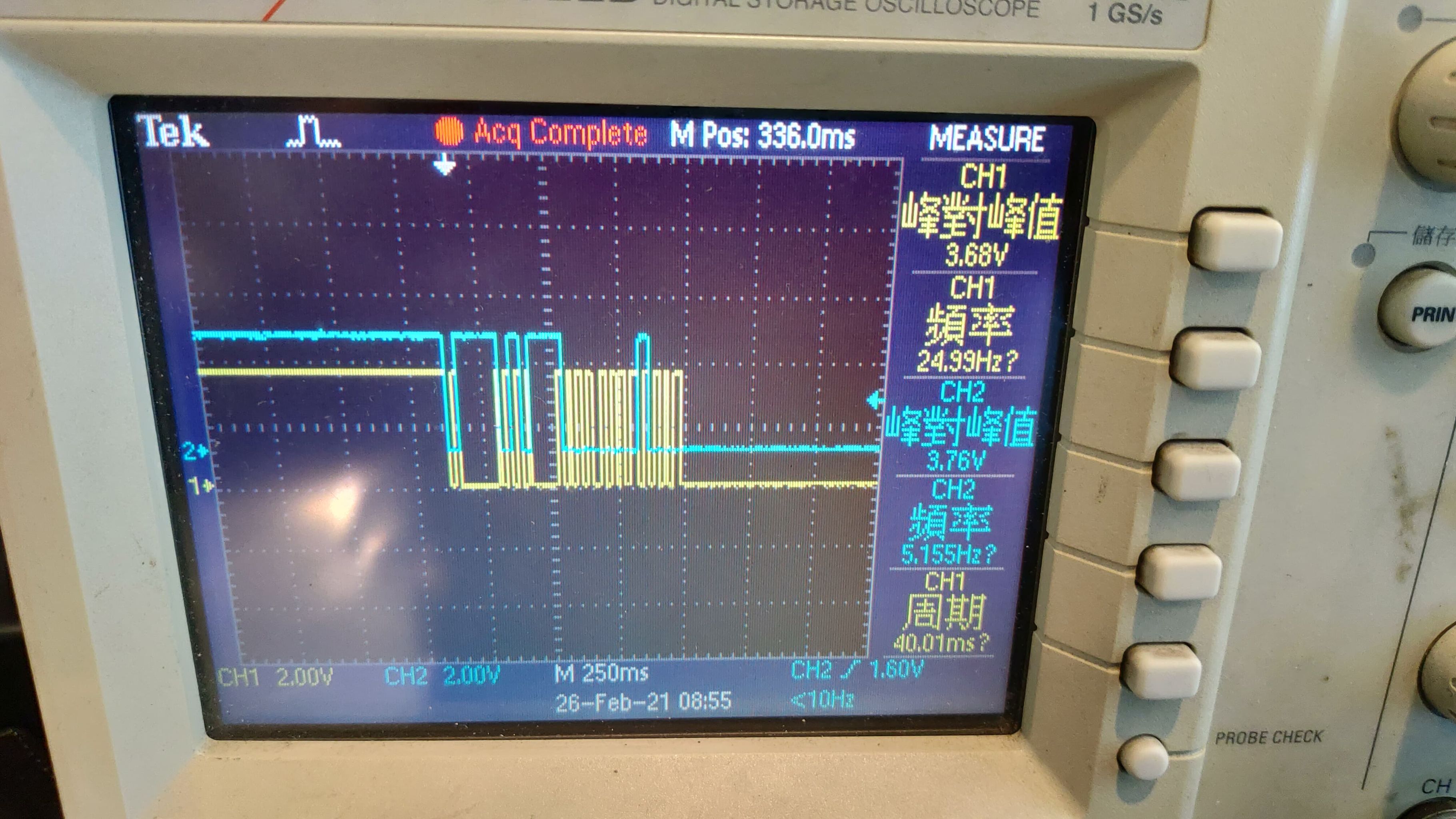
其中黃色為SCLK,藍色為SDA,下圖為示波器上看到的值。

可以看到一開始為高電位,但是結束後卻沒有拉回到高電位。

還請各位先進與高手幫忙解答,感謝


  • 请问您现在从设备是什么?建议您根据从设备I2C的时序要求,增加驱动程序里等待响应的时间试试。

    另外网络上有一些比较好的故障分析,您也可以先看一下

    www.jianshu.com/.../95f53ca2724e
  • Susan 您好,

    MSP43-G2553 (EXP430G2) with the FDC2212(Captative to digital IC).

     BCSCTL1 = CALBC1_8MHZ;                    //

     DCOCTL = CALDCO_8MHZ;                     //

     array[0] = 0x08;  array[1]=0xff;    array[2]= 0xff;     // RCOUNT = ffff

     while ( TI_USCI_I2C_notready() );     // wait for bus to be free

     TI_USCI_I2C_transmitinit(0x2a,ISPEED);

     while ( TI_USCI_I2C_notready() );     // wait for bus to be free

     TI_USCI_I2C_transmit(3,array);        // transmit the first three bytes from array

    ++ 傳遞之後,波型如下:

    i2C 外掛 10k 歐姆,有pull high.

    想要跟您請教:

    1. 如何通常pull high電阻會用多少?

    2. 如何增加延遲時間以利i2c能夠順利傳送資料(避免佔線問題)

    謝謝您

    lin

  • user6529956 说:
    1. 如何通常pull high電阻會用多少?

    一般使用的是10K

    例程的话,您可以参考链接中的一系列I2C例程

    对于 FDC2212,我们也有一个专门的文档,您可以看一下

    另外请您以附件形式上传一下图片,谢谢

  • Dear Susan,

    非常感謝您的迅速回復,我已經有參考過FDC2212的文件。

    至於圖形有兩個疑問:

    1. 為何傳完資料後,SDA與SCLK並沒有拉高準位? (資料內容請參考我前一封提問)

    2. 為何資料看起來跟我要傳的,完全對不起來?

    拜託Susan指導

  • Dear Susan,

    需要您的特別幫忙,

    我參考TI_USCI_I2C_master.c 檔案

    //------------------------------------------------------------------------------
    // void TI_USCI_I2C_transmit(unsigned char byteCount, unsigned char *field)
    //
    // This function is used to start an I2C communication in master-transmit mode.
    //
    // IN: unsigned char byteCount => number of bytes that should be transmitted
    // unsigned char *field => array variable. Its content will be sent.
    //------------------------------------------------------------------------------
    void TI_USCI_I2C_transmit(unsigned char byteCount, unsigned char *field){
    TI_transmit_field = field;
    byteCtr = byteCount;
    UCB0CTL1 |= UCTR + UCTXSTT; // I2C TX, start condition
    }

    並在主程式中,欲傳遞以下資料
    array[0] = 0x08; array[1]=0xff; array[2]= 0xff; // RCOUNT = ffff
    while ( TI_USCI_I2C_notready() ); // wait for bus to be free
    TI_USCI_I2C_transmit(3,array);


    但是用示波器去看,總是有問題(SCLK 看起來都會掉Clock,SDA資料看起也不對)
    ,可以拜託您幫忙看一下 程式碼有無問題嗎?

    感謝~
  • 若是可以的话,请您私信/上传一下您的完整代码,谢谢
  • 6138.main.c
    Fullscreen
    1
    2
    3
    4
    5
    6
    7
    8
    9
    10
    11
    12
    13
    14
    15
    16
    17
    18
    19
    20
    21
    22
    23
    24
    25
    26
    27
    28
    29
    30
    31
    32
    33
    34
    35
    36
    37
    38
    39
    40
    41
    42
    43
    44
    45
    46
    47
    48
    49
    50
    51
    52
    53
    54
    55
    56
    57
    58
    59
    60
    61
    62
    63
    64
    65
    66
    67
    /*** USCI master library ************************************************************
    In this file the usage of the USCI I2C master library without DMA support is
    shown. This library uses pointers to specify what data is to be sent.
    When calling the TI_USCI_I2C_receive or TI_USCI_I2C_transmit routines
    the number of bytes, which are to be transmitted or received have to be passed as
    well as a pointer to a data field, that contains(or stores) the data.
    This code checks if there is a slave with address 0x50 is connected to the I2C
    bus and if the slave device is present, bytes are received and transmitted.
    Uli Kretzschmar
    MSP430 Systems
    Freising
    Added FDC2212-Q1 code for TIDA-01409 Capacitive Kick-to-Open Reference Design
    *******************************************************************************/
    #include "msp430g2553.h"
    #include "TI_USCI_I2C_master.h"
    #define DATA_CH0_MSB_REG 0x00
    #define DATA_CH0_LSB_REG 0x01
    #define DATA_CH1_MSB_REG 0x02
    #define DATA_CH1_LSB_REG 0x03
    ///#define ISPEED 0x3F
    #define ISPEED 63
    //#define ISPEED 12
    #define MARGIN 500
    signed char byteCtr;
    signed char Alive=0;
    unsigned char *TI_receive_field;
    unsigned char *TI_transmit_field;
    unsigned char timercounter;
    unsigned char array[3] = {0x00, 0x00, 0x00 };
    unsigned char store[10] = { 0xff, 0xff };
    unsigned char LSB_Channel_0[2] = { 0x0, 0x0};
    unsigned char MSB_Channel_0[2] = { 0x0, 0x1};
    unsigned char LSB_Channel_1[2] = { 0x0, 0x2};
    unsigned char MSB_Channel_1[2] = { 0x0, 0x3};
    unsigned char MUX_CNFG[2] = {0x00,0x00};
    unsigned char RCOUNT_0[2] = {'R','0'};
    unsigned char RCOUNT_1[2] = {'R','1'};
    unsigned char SCOUNT_0[2] = {'S','0'};
    unsigned char SCOUNT_1[2] = {'S','0'};
    unsigned char IDRIVE_0[3] = {0x1E,0x78,0x00};
    unsigned char IDRIVE_1[3] = {0x1F,0x78,0x00};
    unsigned char CK_DIV_0[2] = {'C','D'};
    unsigned char CK_DIV_1[2] = {'c','d'};
    unsigned char ERR_CNFG[2] = {'E','C'};
    unsigned char CONFIG[2] = {'C','F'};
    unsigned short DataChannel_0_MSB ;
    unsigned short DataChannel_0_LSB ;
    unsigned long DataChannel_0 ;
    unsigned short DataChannel_1_MSB=0 ;
    unsigned short DataChannel_1_LSB=0;
    unsigned long DataChannel_1 ;
    unsigned long Measurement1;
    unsigned long Measurement2;
    unsigned long Measurement3;
    void main(void)
    {
    XXXXXXXXXXXXXXXXXXXXXXXXXXXXXXXXXXXXXXXXXXXXXXXXXX
    Dear Susan,

    目前看起來I2c已經能夠正常傳遞資料,不過對於FDC2212的量測,仍然不清楚,

      // Read the MSB of Channel 1 Data

         while ( TI_USCI_I2C_notready() );     // wait for bus to be free

         TI_USCI_I2C_transmitinit(0x2a,ISPEED);// init transmitting to slave 2a with baud rate SMCLK / 3f (3f = 63) that is, 8 MHz / 63 = 126 kHz

         array[0] = 0x02;                      // register for DATA_CH1    MSB of channel 1 data

         while ( TI_USCI_I2C_notready() );     // wait for bus to be free

         TI_USCI_I2C_transmit(1,array);        // transmit the first byte from array

         while ( TI_USCI_I2C_notready() );     // wait for bus to be free

         TI_USCI_I2C_receiveinit(0x2a,ISPEED); // init receiving with USCI

         while ( TI_USCI_I2C_notready() );     // wait for bus to be free

         TI_USCI_I2C_receive(2,MSB_Channel_1); // receive 2 bytes from FDC

         DataChannel_1_MSB = MSB_Channel_1[0] * 256 + MSB_Channel_1[1];

         // Read the LSB of Channel 1 Data

         while ( TI_USCI_I2C_notready() );     // wait for bus to be free

         TI_USCI_I2C_transmitinit(0x2a,ISPEED);// init transmitting to slave 2a with baud rate SMCLK / 3f (3f = 63) that is, 8 MHz / 63 = 126 kHz

         array[0] = 0x03;                      // register for DATA_CH1_LSB    LSB of channel 1 data

         while ( TI_USCI_I2C_notready() );     // wait for bus to be free

         TI_USCI_I2C_transmit(1,array);        // transmit the first byte from array

         while ( TI_USCI_I2C_notready() );     // wait for bus to be free

         TI_USCI_I2C_receiveinit(0x2a,ISPEED); // init receiving with USCI

         while ( TI_USCI_I2C_notready() );     // wait for bus to be free

         TI_USCI_I2C_receive(2,LSB_Channel_1); // receive 2 bytes from FDC

         DataChannel_1_LSB = LSB_Channel_1[0] * 256 + LSB_Channel_1[1];

         Measurement1 = DataChannel_1_MSB * 65536 + DataChannel_1_LSB;

    程式中,重複兩次(Measurement1),接下來還有Measurement2&3.

    最後利用這個判斷式,判斷電路是否有效觸發:(Margin 設為500)

    if((Measurement1 > (Measurement2 + MARGIN)) && (Measurement3 > (Measurement2 + MARGIN)))

    能否請您指導該如何做實驗,來提升判斷的準確度,謝謝您!

  • 之后我们将在下面的链接讨论

    e2echina.ti.com/.../624314