This thread has been locked.
If you have a related question, please click the "Ask a related question" button in the top right corner. The newly created question will be automatically linked to this question.
UART spi模式下,spi时钟设置成4M时,主程序给txbuf一个字节时,spi接口却会连续重复发送两次该字节!
附测试程序,及SCK和SIMO波形图,求解释。
器件:MSP430F1611
IAR: 5.10
测试程序:
#include <msp430x16x.h>
void InitUART(void)
{
//时钟设置
BCSCTL1 &= ~XT2OFF; //开启8M时钟
BCSCTL2 += SELM_2; //设置MCLK为8M时钟输入
P3SEL |= BIT1 + BIT2 + BIT3;//0x3E; // P3.1,2,3,4,5 = USART0 SIMO, SOMI,UCLK
P3DIR |= BIT1 + BIT3 + BIT0;//0x1B; //
P3DIR &= ~BIT2;//
P3OUT |= BIT0; //
P5DIR |= BIT4;
P5OUT |= BIT4;
UCTL0 |= SWRST;
ME1 |= USPIE0; // Enable USART0 T/RXD
IE1 |= URXIE0; // enable interrupts
IE1 |= UTXIE0;
UCTL0 |= CHAR+SYNC+MM; // 8-bit character, SPI mode, Master
UTCTL0 |= SSEL1+STC+CKPL; // UCLK = SMCLK,3pin SPI mode
BCSCTL2 |= SELS + DIVS_0; //SMCLK = MCLK/1
UBR00 = 0x02;//0x20; // 8M/2=4M
UBR10 = 0x00; //
UCTL0 &= ~SWRST; // Initialize USART state machine
}
main( void )
{
// Stop watchdog timer to prevent time out reset
WDTCTL = WDTPW + WDTHOLD;
InitUART();
while(1)
{
while (!(IFG1 & UTXIFG0)); //判断发送缓存是否为空
TXBUF0 = 0x01;
while (!(IFG1 & UTXIFG0)); //判断发送缓存是否为空
TXBUF0 = 0x0F;
}
}
主程序: spi轮流输出0x01,0x0F.
实测IO:
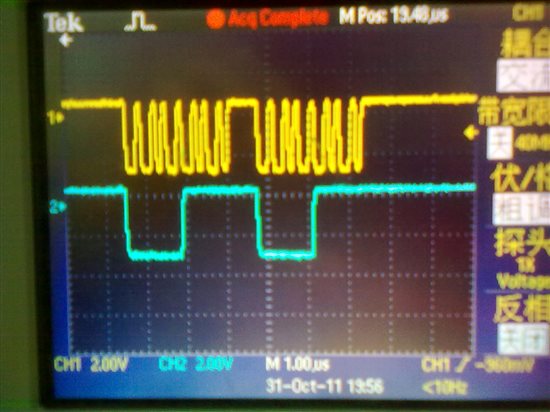
下图中,黄色信号为SCK,蓝色信号为SIMO。可以看到,从左到右SIMO依次传输数据为:0x0F,0x0F,0x01,0x01。
水平时基1us下的视图:
//******************************************************************************
// MSP430G2x21/G2x31 Demo - SPI full-Duplex 3-wire Slave
//
// Description: SPI Master communicates full-duplex with SPI Slave using
// 3-wire mode. The level on P1.4 is TX'ed and RX'ed to P1.0.
// Master will pulse slave reset for synch start.
// ACLK = n/a, MCLK = SMCLK = Default DCO
//
// Slave Master
// MSP430G2x21/G2x31 MSP430G2x21/G2x31
// ----------------- -----------------
// | XIN|- /|\| XIN|-
// | | | | |
// | XOUT|- --|RST XOUT|-
// | | /|\ | |
// | RST/NMI|--+<----|P1.2 |
// LED <-|P1.0 | | P1.4|<-
// ->|P1.4 | | P1.0|-> LED
// | SDI/P1.7|<-------|P1.6/SDO |
// | SDO/P1.6|------->|P1.7/SDI |
// | SCLK/P1.5|<-------|P1.5/SCLK |
//
// D. Dang
// Texas Instruments Inc.
// October 2010
// Built with CCS Version 4.2.0 and IAR Embedded Workbench Version: 5.10
//******************************************************************************
#include <msp430g2221.h>
void main(void)
{
WDTCTL = WDTPW + WDTHOLD; // Stop watchdog timer
P1OUT = 0x10; // P1.4 set, else reset
P1REN |= 0x10; // P1.4 pullup
P1DIR = 0x01; // P1.0 output, else input
USICTL0 |= USIPE7 + USIPE6 + USIPE5 + USIOE; // Port, SPI slave
USICTL1 |= USIIE; // Counter interrupt, flag remains set
USICTL0 &= ~USISWRST; // USI released for operation
USISRL = P1IN; // init-load data
USICNT = 8; // init-load counter
_BIS_SR(LPM0_bits + GIE); // Enter LPM0 w/ interrupt
}
// USI interrupt service routine
#pragma vector=USI_VECTOR
__interrupt void universal_serial_interface(void)
{
if (0x10 & USISRL)
P1OUT |= 0x01;
else
P1OUT &= ~0x01;
USISRL = P1IN;
USICNT = 8; // re-load counter
}
发个demo例子参考一下,自己配置一下.